is.12032.4.1987 graphical symbols for diagrams in the field of electrotechnology, part 4 passive...
TRANSCRIPT

Disclosure to Promote the Right To Information
Whereas the Parliament of India has set out to provide a practical regime of right to information for citizens to secure access to information under the control of public authorities, in order to promote transparency and accountability in the working of every public authority, and whereas the attached publication of the Bureau of Indian Standards is of particular interest to the public, particularly disadvantaged communities and those engaged in the pursuit of education and knowledge, the attached public safety standard is made available to promote the timely dissemination of this information in an accurate manner to the public.
इंटरनेट मानक
“!ान $ एक न' भारत का +नम-ण”Satyanarayan Gangaram Pitroda
“Invent a New India Using Knowledge”
“प0रा1 को छोड न' 5 तरफ”Jawaharlal Nehru
“Step Out From the Old to the New”
“जान1 का अ+धकार, जी1 का अ+धकार”Mazdoor Kisan Shakti Sangathan
“The Right to Information, The Right to Live”
“!ान एक ऐसा खजाना > जो कभी च0राया नहB जा सकता है”Bhartṛhari—Nītiśatakam
“Knowledge is such a treasure which cannot be stolen”
“Invent a New India Using Knowledge”
है”ह”ह
IS 12032-4 (1987): Graphical symbols for diagrams in thefield of electrotechnology, Part 4: Passive components [ETD1: Basic Electrotechnical Standards]


-, C 7 1
.! i
d 4 c
?
:
d 7 .! : :
1 i 9 P
.h : a
IS : 621*3i61
12032 ( Part 4 ) - 1987 UDC : 003.62 IEC Pub 617 - 4 ( 1983 )
Indian Standard
GRAPHICAL SYMBOLS FOR DIAGRAMS IN THE FIELD OF ELECTROTECHNOLOtiY
PART 4 PASSIVE COMPONENTS
( [EC Title : Graphical Symbols for Diagrams - Part 4 : Passive Components )
National Foreword
This Indian Standard ( Part 4 ) which is identical with IEC Pub 617-4 (1983) ‘Graphical symbols for diagrams - Part 4 : Passive components’; issued by the International Electrotechnical Commission ( IEC ): was adopted by the Bureau of Indian Standards on the recommendation of the Basic Electrotechnical Standards Sectional C0mmitte.e and approval of the Electrotechnical Division Council.
Cross Reference
International Standard
IEC Pub 617-6 (1983) Graphical symbols for dia- grams : Part 6 Production and conversion of electrical energy
Corresponding Indian Standard
IS : 12032 ( Part 6 )-1987 Graphical symbols for diagrams in the field of electrotechno- logy : Part 6 Production and conversion of electrical energy
Adopted 18 June 1987 I cIJ September 1988, BIS I Gr 6
BUREAU OF INDIAN STANDARDS MANAK BHAVAN, 9 BAHADUR SHAH ZAFAR MAR6
NEW DELHI 110002
.~.., . i : .

As in the Original Standard, this Page is Intentionally Left Blank

IS : 12032 (Part 4)-1987 IEC Pub 617-4 (1983)
CHAPTER I: RESISTORS, CAPACITORS, INDUCI-ORS
SECTION 1 - RESISTORS
No
W-01-01
04-01-02
04-01-03
Symbol
Preferred form D
Other form
#
Description
Resistor, general symbol
Variable resistor
Adjustable resistor
04-01-W
04-01-05
04-01-06
04-01-07
Voltage dependent resistor
Varistor
(Resistor with inherent non-linear variability voltage
dependent)
Note. - U may be replaced by V.
Resistor with sliding contact
Resistor with sliding contact and off position
Potentiometer with sliding contact
---___-
Potentiometer, pre-set
,_~
Resistor with fued tappjngs (taps), two shown
04-01-10
u-
Shunt
Resistor with separate current and voltage terminals
04-01-11 Carbon-pile resistor
04-01-12 Heating element
3

IS : 12032 (Part 4)-19th IEC Pub 617-4 (1983)
SEC7’ION 2 - CAPACITORS
2.1 TWO form are shown, but both should not be used on the same
diagram.
No.
0442-01
Symbol Description _____
Preferred form Other form
-__
+ Capacitor, general symbol
04-02-u2 Nore. - If it is necessary to identify the capacitor elec- bodes, the curved element shall represent;
- the outside electrode in fixed paper-dielectric and ceramic-dielectric capacitors;
- the moving element in adjustable and variable capacitors;
-- the low-potential element in feed-through capacitors.
cM-cr2-03
T
Lead-through capacitor Feed-through capacitor
LMu2-04 T
M-02-05
B442-06
la-mm
+1, T
#
-_.. _-- .._. Polarized capacitor. for example electrolytic
-_--
+l T
i Variabk capacitor Adjustabk capacitor
SF
Capacitor with pre-set adjustment

No.
04-02-11
04-02-12
Description
Variable differential capacitor
Variable split capacitor
T Temperature dependent polarized capacitor, where de- liberate use is made of the temperature coefficient, for
5

IS : 12032 (Part 4)-1987 IEC Pub 617-4 (1983)
No. symboi
04-03-01
04-03-02
04-03-03
04-03-04
04-03-0s
04-03-06
M-03-07
04-03-08
04-0349
0443- 10
SECTION 3 - INDUCTORS
Preferred form
Other form
r-l -- r-7
/ 77 P-l
f-T-
*
-Eszs-- - I I
6
5
1 Inductor with fLxed tappings (taps), two shown
Inductor with moving contact, variable in steps
Variometer
Coaxial choke with magnetic core
_I-_ Ferrite bead, shown on a conductor
Inductor Coil Winding Choke
Notes 1. - For transformer windings, see IEC Publica- tion 617-6: Graphical Symbols for Diagrams, Part 6: Production and Conversion of Elec- trical Energy.
2. - If it is desired to show that the inductor has a magnetic core, a single line may be added to the symbol. The line may be annotated to indicate non-magnetic materials and it may be interrupted to indicate a gap in the core.
Examples:
Inductor with magnetii: core
Inductor with gap in magnetic core
Continuously variable inductor, shown with magnetic core

IS : 12032 (Part 4)-1987 IEC Pub 617-4 (1983)
CHAPTER II: FERRlTEI CORES AND MAGNETIC
STORAGE MATRICES
SECTION 4 - SYMBOL ELEMENTS
No.
o4-04-01
SplbOl
I
Ferrite core
Description
/\ or
Fhrxlcurrent direction indicator
This symbol indicates that a horizontal line drawn at a right angle through a core symbol represents a core winding, and it also gives the ielative directions of cur- rent and flux.
Note. - This symbol is not applicable for topographical representation.
04-04-03
-+
Ferrite core with one winding
The oblique tine may be regarded as a reflector that relates the directions of current and flux as shown below.
t Flux
Current +-
or
-++ +
Current
Flux For drawing convenience, lines representing conductors are often shown crossing core symbols even though there is no winding on the magnetic circuit. Except in topographical representation the use of the oblique stroke is mandatory in all cases where a line through the core symbol represents a winding.
Example:
Jk
l )
** )
*) Conductor crossing the core symbol
l *) Winding on the core
7

IS : 12032 (Part 4)-1987 IEC Pub 617-4 (1983)
SECTION 5 - FERRITE CORES
No.
o4-05-01
Symbol Description
Ferrite core with five windings
Note. - Information on the direction of current, its rela-
tive amplitude and the logic conditions imposed
by the state of the magnetic remanence may be
added.
+
Ferrite core with one winding of m turns
N=m
SECTION 6 - MAGNETIC STORAGE MATRICES (TOPOGRAPHICAL REPRESENTATION)
Ferrite core matrix with x and y windings and a read-out
winding. The symbol of a ferrite core, 04-04-01, is
shown at 45” to the horizontal
Matrix arrangement comprising thin sheet magnetic
stores, located between thin sheet wiring layers
8
IS : 12032 (Part 4)-1987 IEC Pub 617-4 (1983)
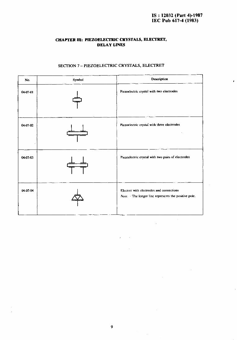
CHAPTER III: PIEZOELECTRIC CRYSTALS, ELECIRET,
DELAY LINES
SECTION 7 - PIEZOELECTRIC CRYSTALS, ELECIRET
No.
04-07-01
Symbol
1
T
Description
Piezoelectric crystal with two electrodes
04-07-02 _L_L Piezoelectric crystal with three electrodes
--r
04-07-03
04-m-04
II
TT
1,
Piezoelectric crystal with two pairs of electrodes
Electret with electrodes and connections
Note. - The longer line represents the positive pole.
IS : 12032 (Part 4)-1987 IEC Pub 617-4 (1983)
-~ No.
04-08-01
04-0X-02
04-OR03
04-08-04
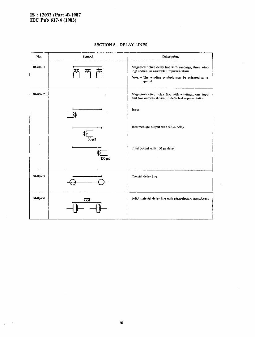
SECTION 8 - DELAY LINES
Symbol
mm
8 I
n n
-iii-
Description
Magnetostrictive delay line with windings, three wind-
ings shown, in assembled representation
Nofe. - The winding symbols may be oriented as re-
quired.
Magnetostrictive delay line with windings, one input
and two outputs shown, in detached representation
Input
Intermediate output with 50 p delay
Final output with 100 p delay
Coaxial delay line
Solid material delay line with piezoelectric transducers
IS : 12032 (Part 4)-1987 IEC Pub 617-4 (1983)
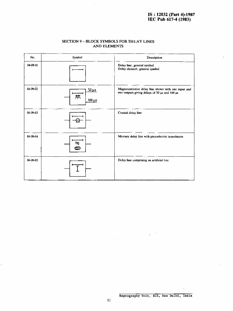
SECTION 9 - BLOCK SYMBOLS FOR DELAY LINES
AND ELEMENTS
No.
04-09-01
Symbol Description
Delay line, general symbol Delay element, general symbol
04-&I-62 Magnetostrictive delay line shown with one input and two outputs giving delays of 50 p and 100 ps
04-09-03 Coaxial delay line
04-09-04 Mercury delay line with piezoelectric transducers
04-09-05 Delay line comprising an artificial line
Reprography Unit, BIS, New Delhi, India
11