fundamentals for building drawing · pdf filethe basics of this graphical language of...
TRANSCRIPT
Fundamentals for building Drawing
What is Drawing
• IntroductionKnowledge of preparing and understanding drawing will prove to be an invaluable aid while performing their jobs effectively, efficiently. All concerned have to understand the basics of this graphical language of engineers.
• Drawing is a pictorial presentation of anything, It’s a means of communication because with the help of drawing, one can communicate the ideas to others. Sometimes, thousand of words can not able to express the ideas, but with the help of drawing, one can communicate most complicated problems also.
An Engineering Drawing is a type of technical drawing, used to fully and clearly define the requirements for engineered items, and is usually created in accordance with standardized conventions for layout, nomenclature, interpretation, appearance (such as typefaces and line styles), size, etc.
Purpose of Drawing To capture all the geometric features of a product or a component accurately
and unambiguously to convey all the required information that will allow a user to understand that
component. A technical drawing is a form of graphic communication. This type of drawing is used in the transforming of an idea into physical form. The process of creating a technical drawing is called drafting or technical drawing.
Different kinds of drawing are prepared for different purposes like
Layout of plans, Drawings for approval of authority,Working and detailed drawings for estimates and construction
Drawings Convey the following critical information
• Geometry• Dimension• Material• Finishes
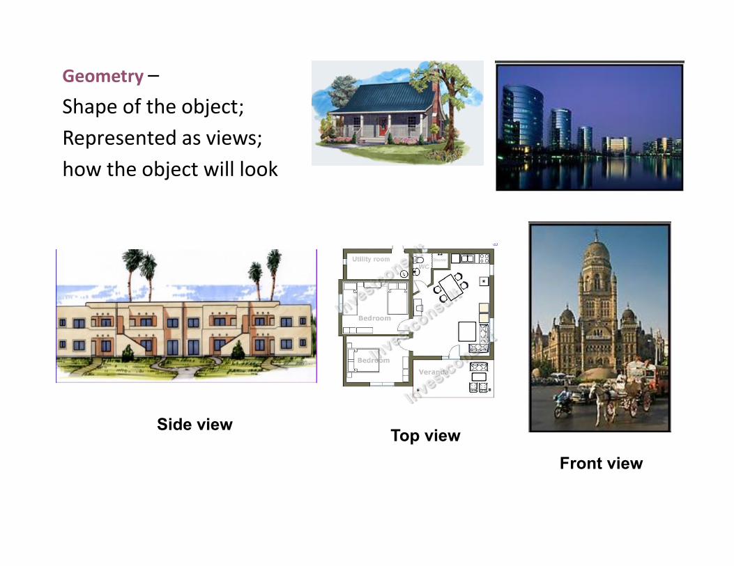
Geometry –Shape of the object; Represented as views; how the object will look
Side view
Front viewTop view

•Dimensions – the size of the object is captured in accepted units
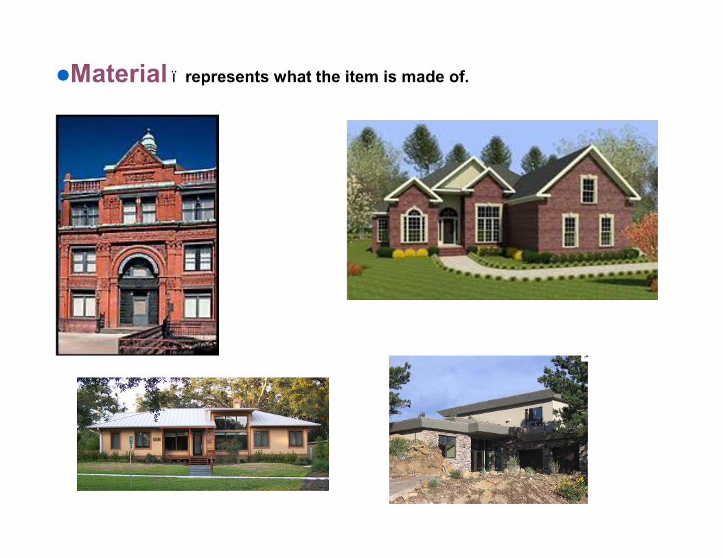
lMaterial – represents what the item is made of.
•Finish – specifies the surface quality of the item, functional or cosmetic. For example, a mass-marketed product usually requires a much higher surface quality than, say, a component that goes inside industrial machinery.
l Tolerances – the allowable variations for each dimension
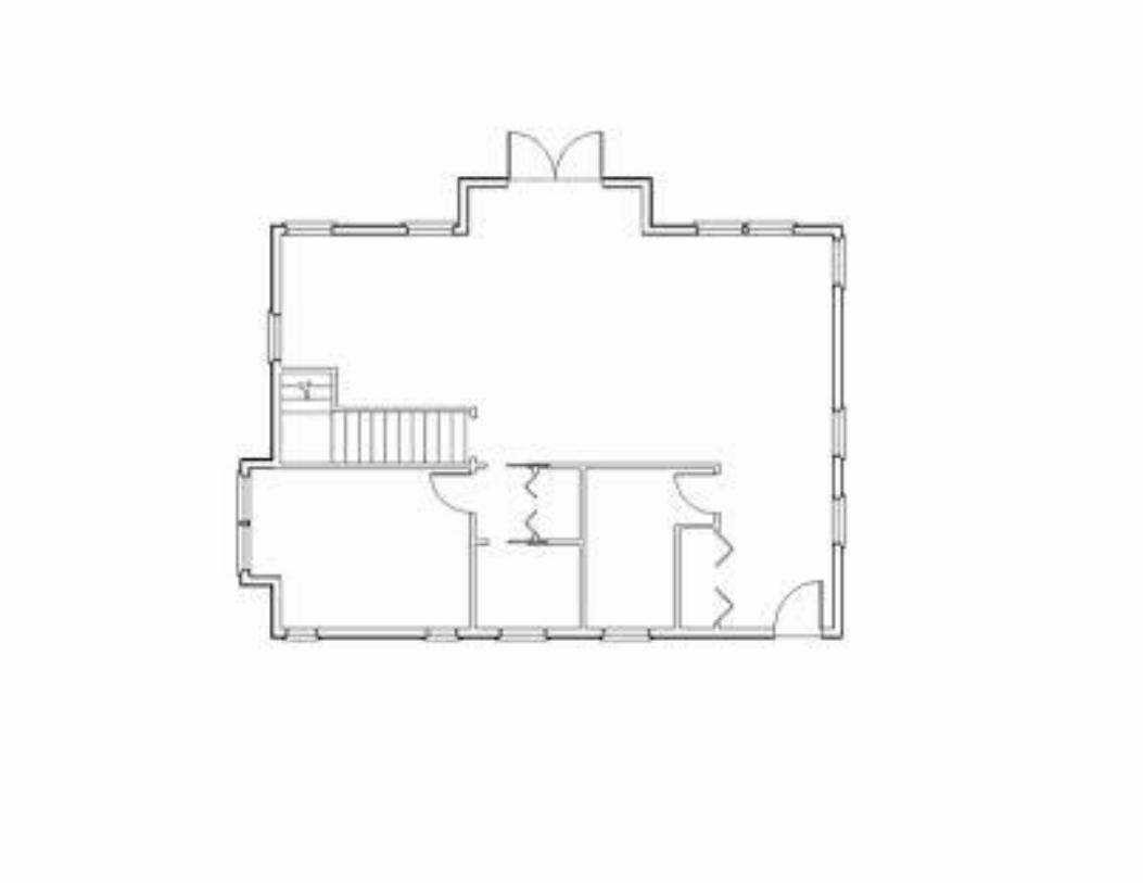
• What we Draw? • Layout of plans • Submission drawing • Working and detailed drawings for estimates
construction• For the contractor to execute the building
• How to Draw? • By graphical language of lines, projections,
projectors • Orthographic and pictorial drawing
• Why we Draw? • For approval of client • For approval of sanctioning authority • Working and detailed drawings for estimates• For the contractor to execute the building
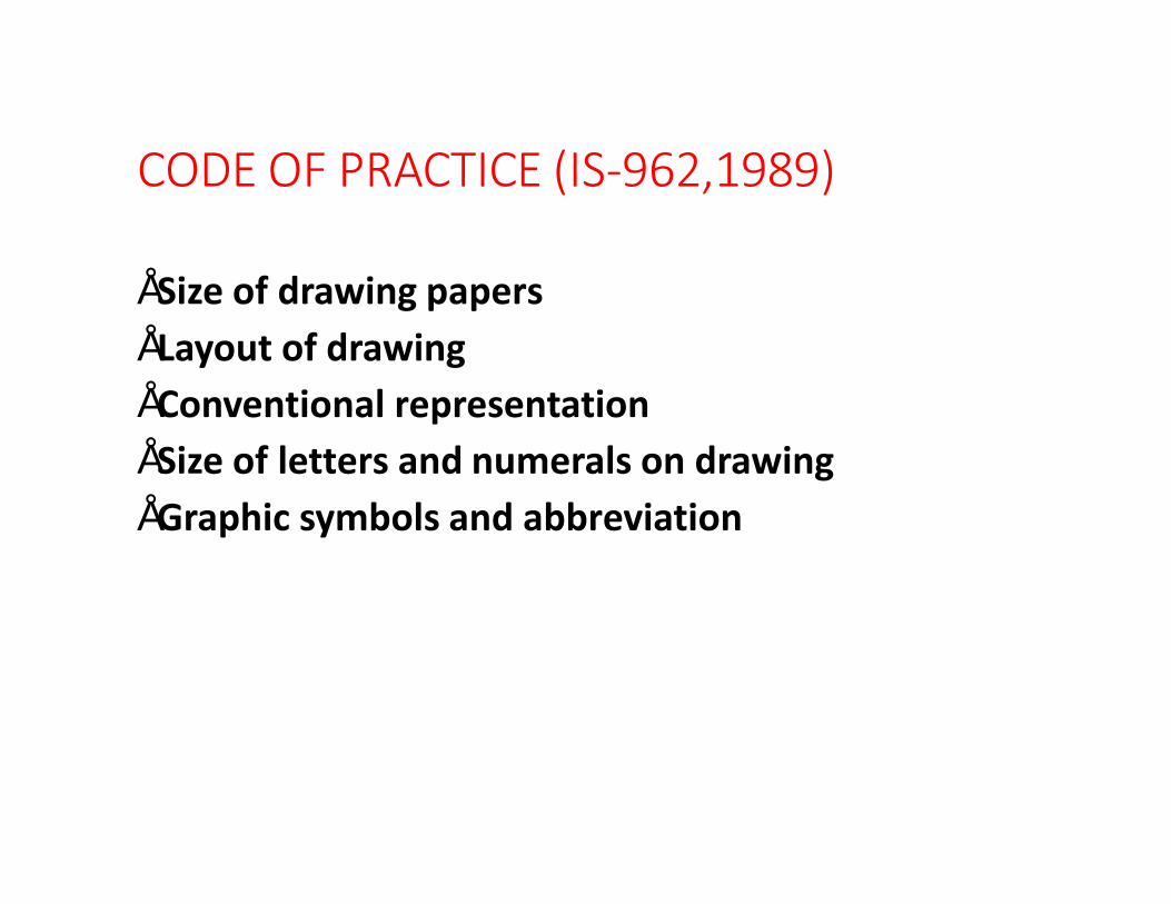
CODE OF PRACTICE (IS-962,1989)
• Size of drawing papers• Layout of drawing• Conventional representation• Size of letters and numerals on drawing• Graphic symbols and abbreviation
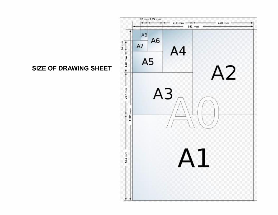
SIZE OF DRAWING SHEET
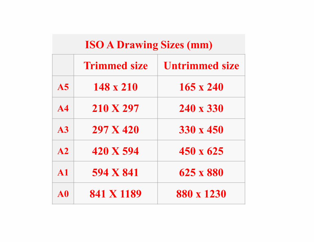
ISO A Drawing Sizes (mm)
Trimmed size Untrimmed size
A5 148 x 210 165 x 240
A4 210 X 297 240 x 330
A3 297 X 420 330 x 450
A2 420 X 594 450 x 625
A1 594 X 841 625 x 880
A0 841 X 1189 880 x 1230
Layout of Drawing
• Border line are drawing all round the drawing sheet leaving margin of 10 mm
• 25 mm to 30 mm on left side for filing
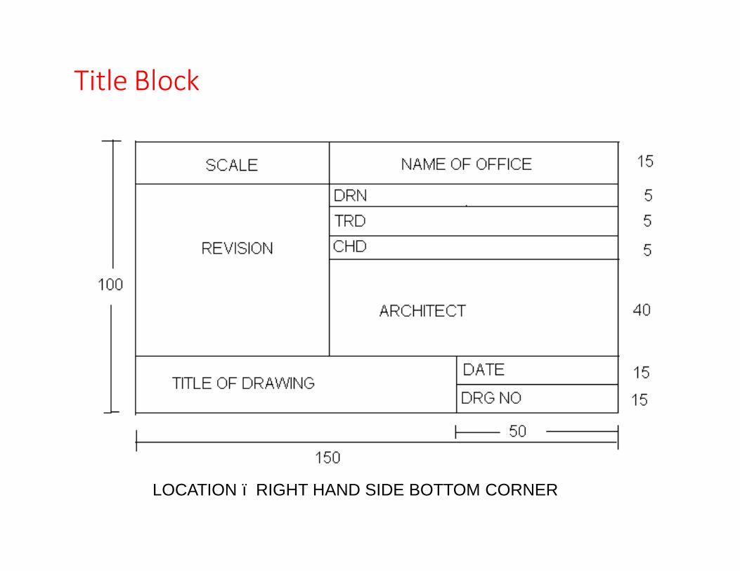
Title Block
LOCATION – RIGHT HAND SIDE BOTTOM CORNER
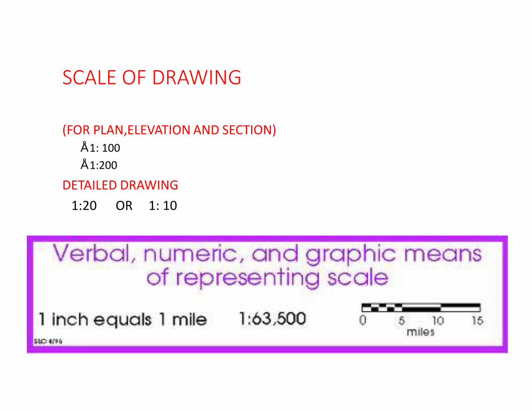
SCALE OF DRAWING
(FOR PLAN,ELEVATION AND SECTION)• 1: 100• 1:200
DETAILED DRAWING1:20 OR 1: 10
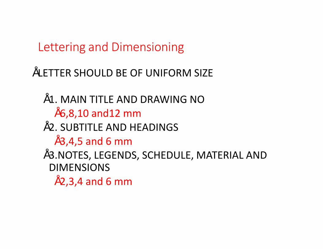
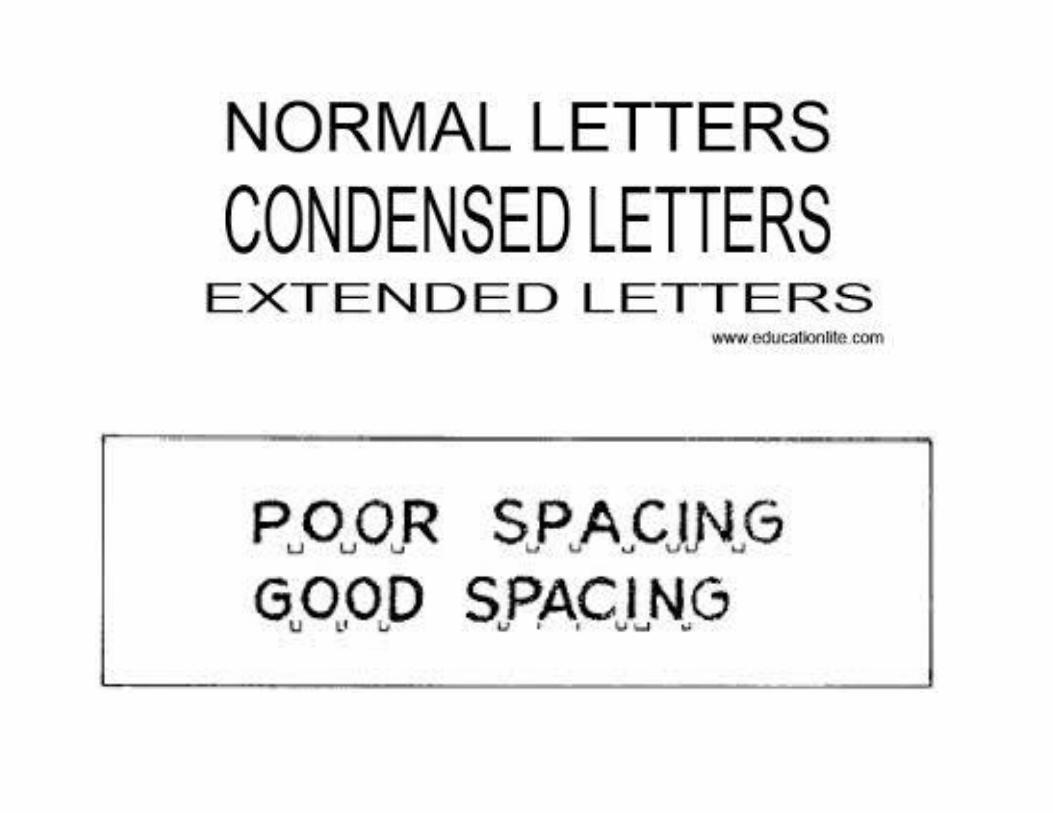
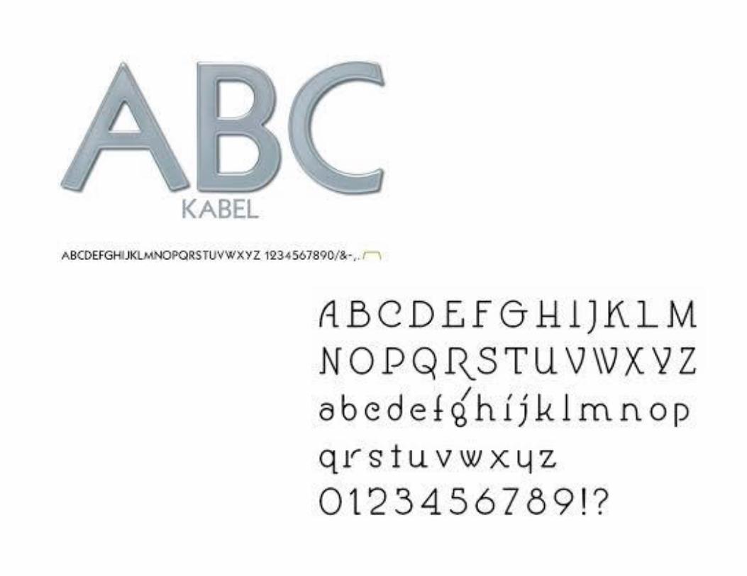
Lettering and Dimensioning
• LETTER SHOULD BE OF UNIFORM SIZE
• 1. MAIN TITLE AND DRAWING NO• 6,8,10 and12 mm
• 2. SUBTITLE AND HEADINGS• 3,4,5 and 6 mm
• 3.NOTES, LEGENDS, SCHEDULE, MATERIAL AND DIMENSIONS• 2,3,4 and 6 mm
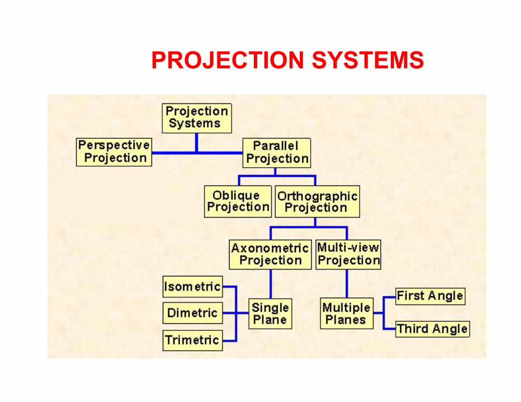
PROJECTION SYSTEMS
PROJECTION SYSTEMS
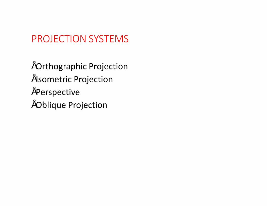
• Orthographic Projection• Isometric Projection• Perspective• Oblique Projection
Orthographic projection:
• Orthographic comes from the Greek word for "straight writing (or drawing)."
• This projection shows the object as it looks from the front, right, left, top, bottom, or back, and are typically positioned relative to each other according to the rules of either first-angle or third-angle projection.
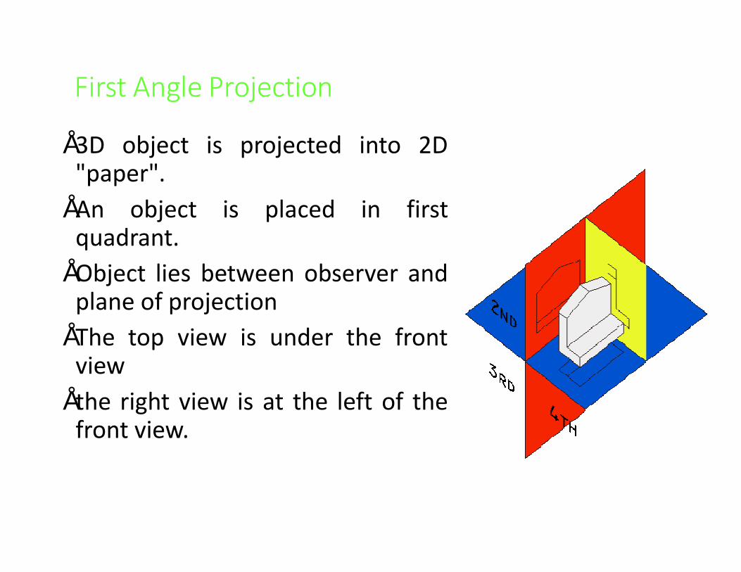
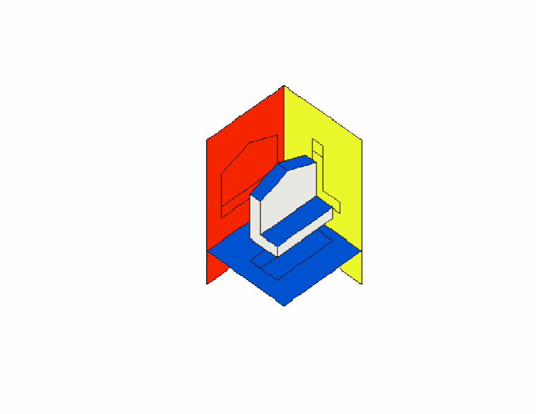
First Angle Projection
• 3D object is projected into 2D"paper".
• An object is placed in firstquadrant.
• Object lies between observer andplane of projection
• The top view is under the frontview
• the right view is at the left of thefront view.
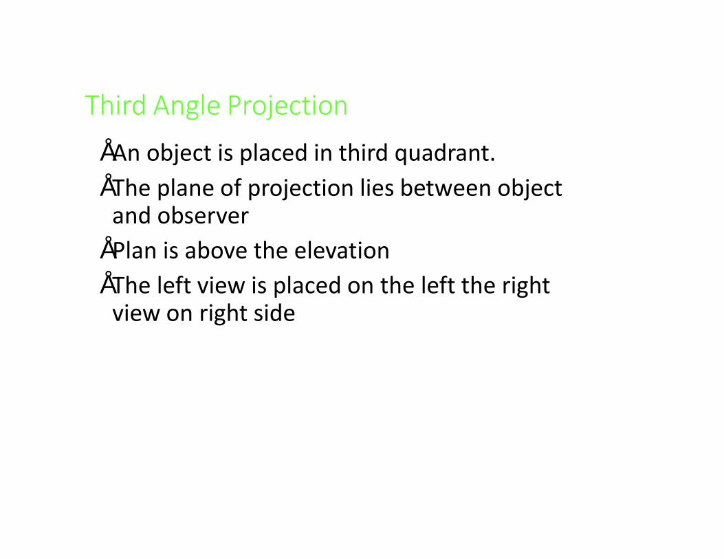
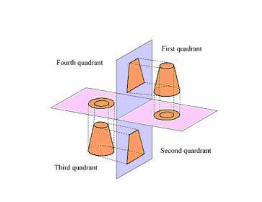
Third Angle Projection• An object is placed in third quadrant.• The plane of projection lies between object
and observer• Plan is above the elevation• The left view is placed on the left the right
view on right side

Combination of First and Third Angle Projection
• Building drawing, we use combination of first and third angle projection
• Plan is below the elevation• In relation to elevation, end view are so placed that
they are in third angle projection• Left view on left and right view on right side
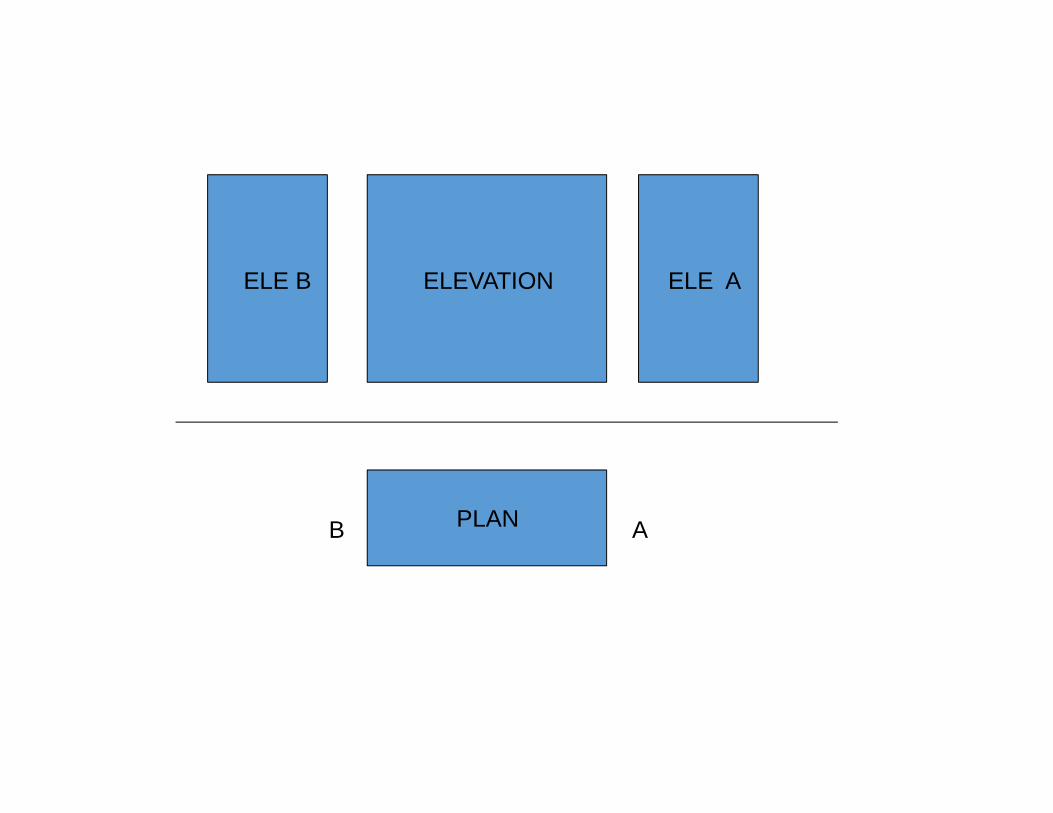
PLAN
ELEVATION ELE AELE B
AB
PLAN
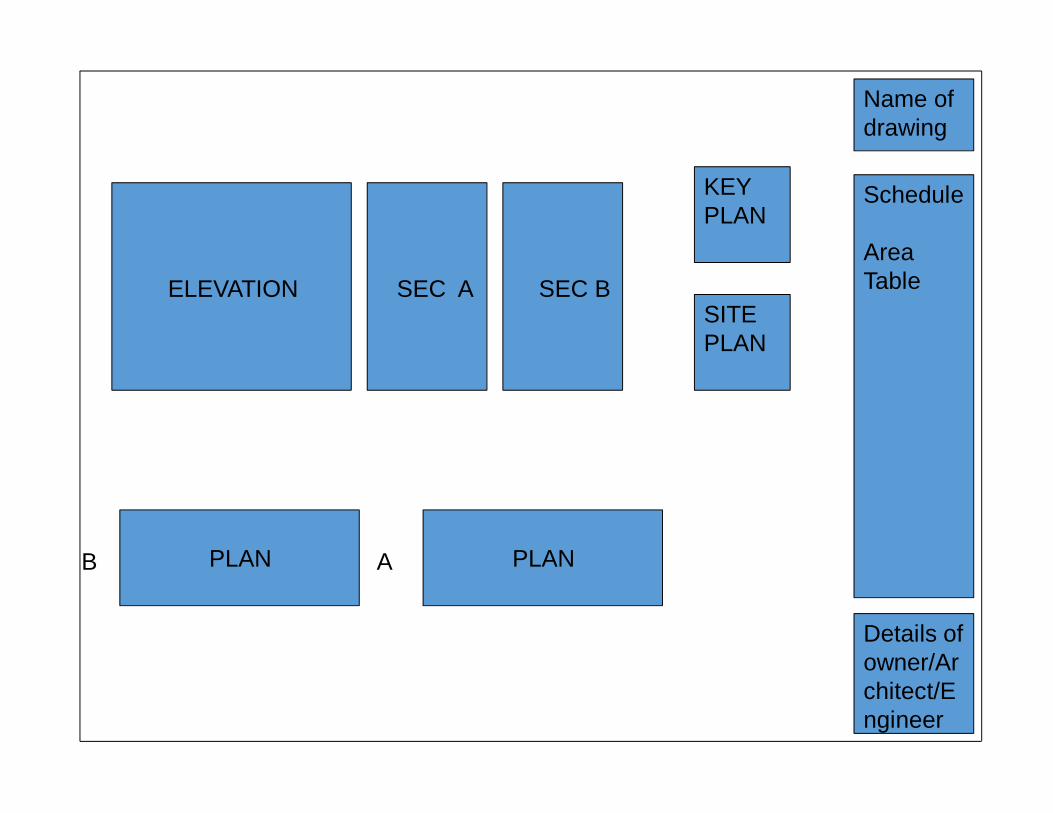
ELEVATION SEC A SEC B
AB PLAN
Schedule
Area Table
Details of owner/Architect/Engineer
KEY PLAN
SITE PLAN
Name of drawing
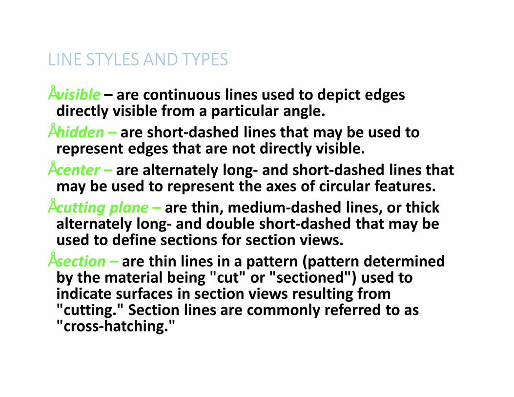
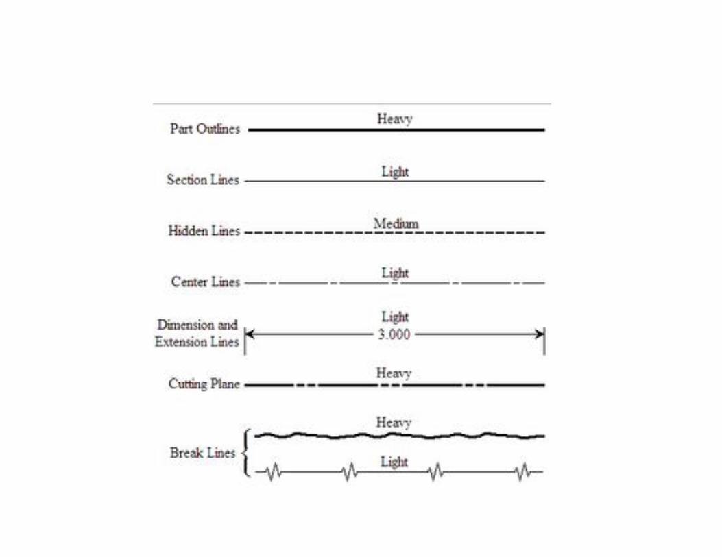
LINE STYLES AND TYPES
• visible – are continuous lines used to depict edges directly visible from a particular angle.
• hidden – are short-dashed lines that may be used to represent edges that are not directly visible.
• center – are alternately long- and short-dashed lines that may be used to represent the axes of circular features.
• cutting plane – are thin, medium-dashed lines, or thick alternately long- and double short-dashed that may be used to define sections for section views.
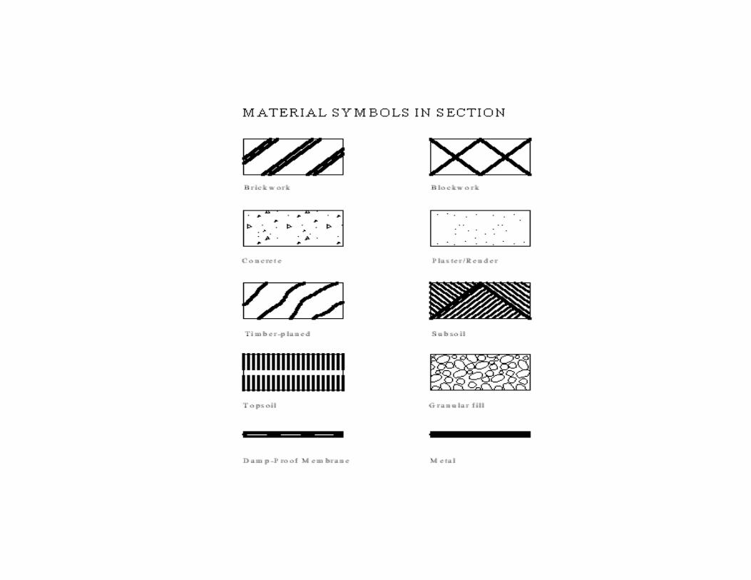
• section – are thin lines in a pattern (pattern determined by the material being "cut" or "sectioned") used to indicate surfaces in section views resulting from "cutting." Section lines are commonly referred to as "cross-hatching."
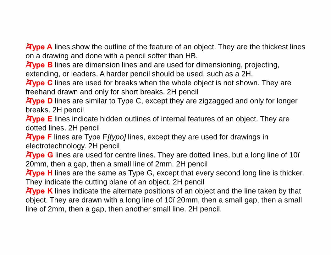
•Type A lines show the outline of the feature of an object. They are the thickest lines on a drawing and done with a pencil softer than HB. •Type B lines are dimension lines and are used for dimensioning, projecting, extending, or leaders. A harder pencil should be used, such as a 2H. •Type C lines are used for breaks when the whole object is not shown. They are freehand drawn and only for short breaks. 2H pencil •Type D lines are similar to Type C, except they are zigzagged and only for longer breaks. 2H pencil •Type E lines indicate hidden outlines of internal features of an object. They are dotted lines. 2H pencil •Type F lines are Type F[typo] lines, except they are used for drawings in electrotechnology. 2H pencil •Type G lines are used for centre lines. They are dotted lines, but a long line of 10–20mm, then a gap, then a small line of 2mm. 2H pencil •Type H lines are the same as Type G, except that every second long line is thicker. They indicate the cutting plane of an object. 2H pencil •Type K lines indicate the alternate positions of an object and the line taken by that object. They are drawn with a long line of 10–20mm, then a small gap, then a small line of 2mm, then a gap, then another small line. 2H pencil.

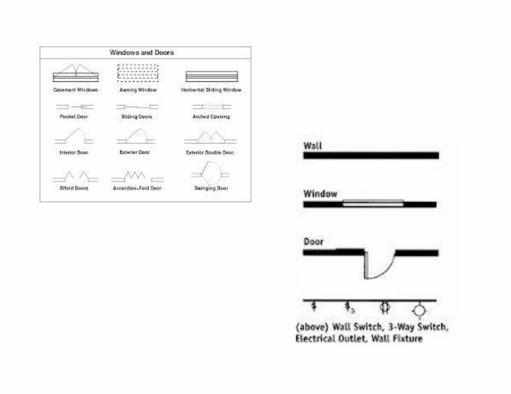
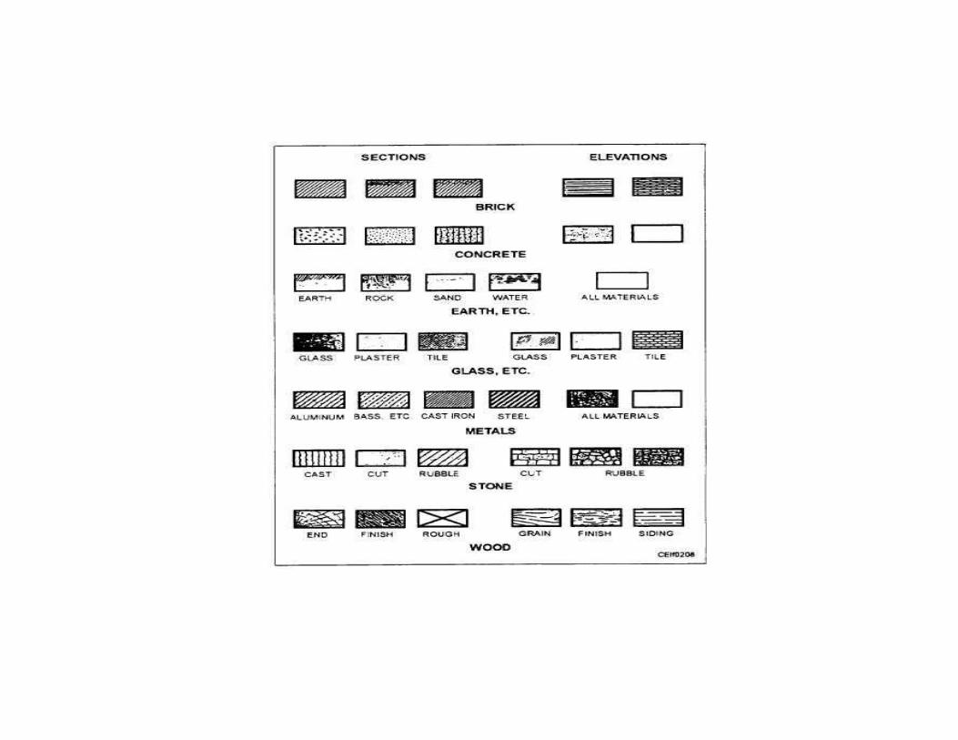
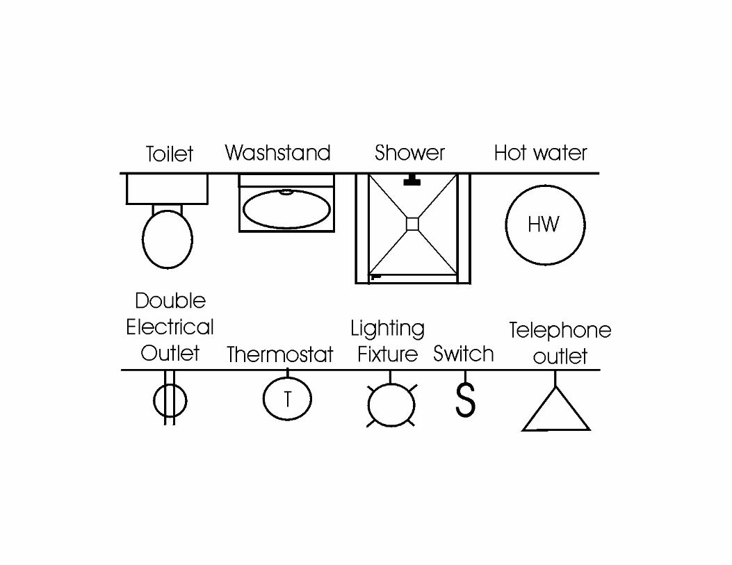
Symbols
• Scale are in constant use on small scaledrawing
• It is considered that time can be saved andconfusion can be avoided.
• It also save the space in drawing.
Abbreviation
•Abbreviation are generally used in drawing for sake ofclarity.•A systematic notation of architectural and building termsis necessary for uniformity and avoiding confusion andambiguity.•Scale used to prepare submission and working drawingsis 1: 200, 1:100, 1:50.