electrotechnology workshop tools and techniques … electrotechnology... · electrotechnology...
TRANSCRIPT
Learner Workbook
Version 1
Training and Education SupportIndustry Skills Unit
Meadowbank
Product Code: 5636
Electrotechnology Workshop Tools and Techniques
SAMPLE

Electrotechnology Workshop Tools and Techniques
© TAFE NSW (Training & Education Support, Industry Skills Unit Meadowbank) 2012
EnquiriesEnquiries about this and other publications can be made to:
Training and Education Support Industry Skills Unit, Meadowbank Meadowbank TAFE Level 3, Building J, See Street, MEADOWBANK NSW 2114
Tel: 02-9942 3200 Fax: 02-9942 3257
© TAFE NSW (Training and Education Support, Industry Skills Unit Meadowbank) 2012
Copyright of this material is reserved to TAFE NSW Training and Education Support, Industry Skills Unit Meadowbank. Reproduction or transmittal in
whole or in part, other than subject to the provisions of the Copyright Act, is prohibited without the written authority of TAFE NSW Training and Education
Support, Industry Skills Unit Meadowbank.
ISBN 978-1-74236-349-3
SAMPLE

© TAFE NSW (Training & Education Support, Industry Skills Unit Meadowbank) 2012
Electrotechnology Workshop Tools and Techniques
Table of Contents
Introduction ................................................................................... 5
Section 1 Mechanical Drawing Interpretation ............................. 7
Section 2 Mechanical Drawing - Sketching ............................... 23
Section 3 Workshop Planning and Materials ............................. 39
Section 4 Measuring and Marking Out ..................................... 49
Section 5 Holding and Cutting .................................................. 73
Section 6 Drills and Drilling ...................................................... 91
Section 7 Tapping and Threading ........................................... 107
Section 8 General Hand Tools ................................................. 121
Section 9 Joining Techniques ................................................. 131
Section 10 Portable Electric Power Tools .................................. 141
Section 11 Sheet Metal Work ................................................... 147
Section 12 Low Tolerance Measurement................................... 157
Section 13 Dismantling and Assembly Techniques ................... 167
Section 14 Hollow Wall Fixing and Support Devices/Methods .. 177
Section 15 Solid Wall Fixing and Support Devices/Methods .... 183
Section 16 Revision, Consolidation and Assessment ................. 189
Sample Theory Test .................................................................... 191
Sample Practical Test 1 .............................................................. 205
Sample Practical Test 2 .............................................................. 209
Review Questions – Answers ...................................................... 213
Resource Evaluation Form .......................................................... 231
SAMPLE

© TAFE NSW (Training & Education Support, Industry Skills Unit Meadowbank) 2012 Page 7 of 234
Electrotechnology Workshop Tools and Techniques
Section 1 Mechanical Drawing Interpretation
Section PurposeIn this section you will learn how to use engineering drawings and the importance of standards and conventions used to allow the interpretation of the information they contain.
Section Topics• Technical drawing standards, conventions and specifications
• Abbreviations and symbols
• Types of drawing representations
• Orthogonal projection
• Third angle – detail and assembly drawings
• Pictorial views.
Learning ObjectivesAt the end of this section you should be able to:
(a) Describe the drawing standards and conventions used in drawings of mechanical components as specified in AS 1100.
(b) Explain the meaning of basic abbreviations and symbols used in drawings of mechanical components.
(c) Identify the commonly used drawing representations used in the electrotechnology Industry.
SAMPLE
Page 8 of 234 © TAFE NSW (Training & Education Support, Industry Skills Unit Meadowbank) 2012
Electrotechnology Workshop Tools and Techniques
Learner Exercises
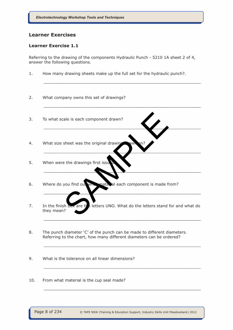
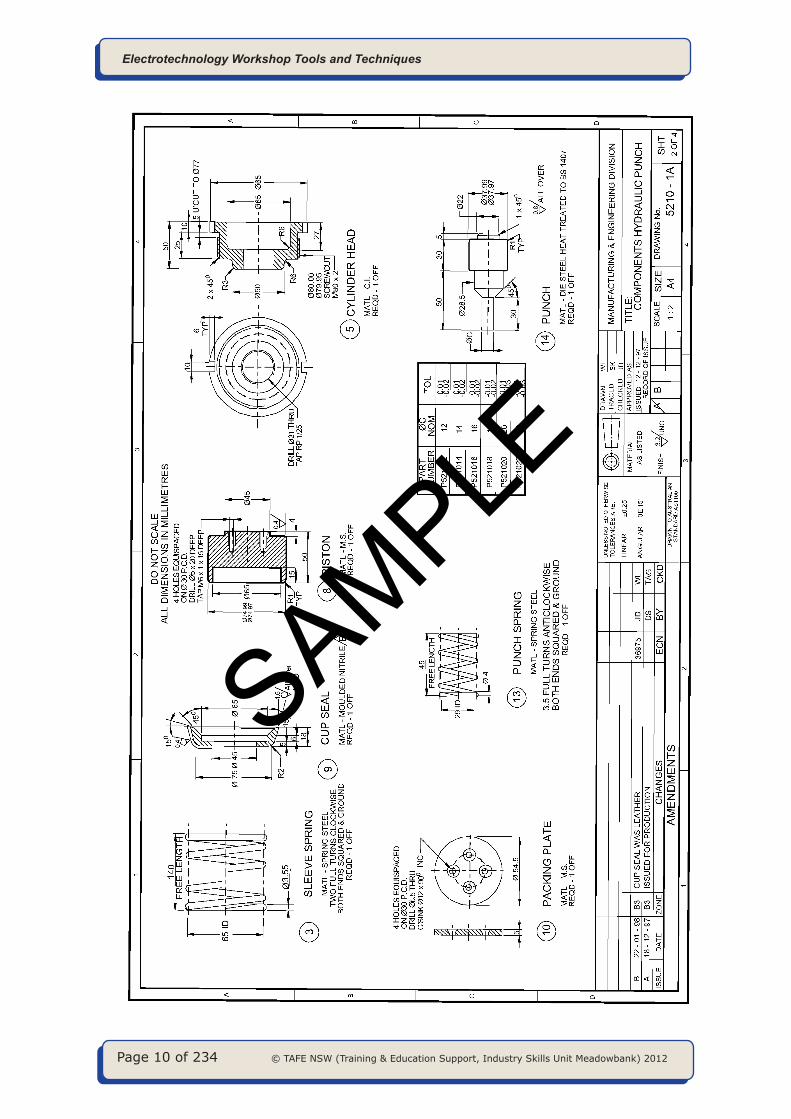
Learner Exercise 1.1
Referring to the drawing of the components Hydraulic Punch - 5210 1A sheet 2 of 4, answer the following questions.
1. How many drawing sheets make up the full set for the hydraulic punch?.
_______________________________________________________________
2. What company owns this set of drawings?
_______________________________________________________________
3. To what scale is each component drawn?
_______________________________________________________________
4. What size sheet was the original drawing drawn on?
_______________________________________________________________
5. When were the drawings first issued?
_______________________________________________________________
6. Where do you find out what material each component is made from?
_______________________________________________________________
7. In the finish box are the letters UNO. What do the letters stand for and what do they mean?
_______________________________________________________________
8. The punch diameter ‘C’ of the punch can be made to different diameters. Referring to the chart, how many different diameters can be ordered?
_______________________________________________________________
9. What is the tolerance on all linear dimensions?
_______________________________________________________________
10. From what material is the cup seal made?
_______________________________________________________________
SAMPLE

© TAFE NSW (Training & Education Support, Industry Skills Unit Meadowbank) 2012 Page 9 of 234
Electrotechnology Workshop Tools and Techniques
11. What is the date of the last issue of the drawing?
_______________________________________________________________
12. The material for the cup seal has been changed since the original issue of the drawing. What material was it originally made from?
_______________________________________________________________
13. What component is named at zone B5?
_______________________________________________________________
14. To what Australian Standard has the drawing been drawn?
_______________________________________________________________
15. Can you tell if the drawing is first or third angle projection from the information in the title block?
_______________________________________________________________
16. How many of each of these components is required when assembling the finished hydraulic punch?
_______________________________________________________________
17. What angular tolerance applies to angles on the components?
_______________________________________________________________
18. What are the initials of the person who approved the original drawing?
_______________________________________________________________
19. How are the ends of the sleeve spring and punch spring to be finished off in manufacture?
_______________________________________________________________
20. In what units are all the dimensions?
_______________________________________________________________
SAMPLE
Page 10 of 234 © TAFE NSW (Training & Education Support, Industry Skills Unit Meadowbank) 2012
Electrotechnology Workshop Tools and Techniques
SAMPLE

© TAFE NSW (Training & Education Support, Industry Skills Unit Meadowbank) 2012 Page 11 of 234
Electrotechnology Workshop Tools and Techniques
Learner Exercise 1.2
Referring to drawing of the Adjusting Pin - 6547-1-1/B, answer the following questions. Tick the correct response where boxes are provided.
1. What type of drawing is it?
_______________________________________________________________
2. What is the part called?
_______________________________________________________________
3. The scale is NTS, what does that mean?
_______________________________________________________________
4. What does ‘AS’ in the material specifications AS CS1040 stand for?
_______________________________________________________________
5. What dimension sizes are located in zone A3? (list three)
1. ___________________ 2. __________________ 3. ___________________
6. What dimension sizes are located in zone C4? (list three)
1. ___________________ 2. __________________ 3. ___________________
7. How can you be sure Issue B is the latest issue?
_______________________________________________________________
8. If you had a copy of the drawing 6547-1-1(issue A) in the workshop would it be up to date and correct? Yes No
9. What part of the Title Block indicates the latest drawing?
Finish Amendments Approved
10. What size drawing sheet was used to produce the original drawing?
A2 A3 A4
SAMPLE

Page 12 of 234 © TAFE NSW (Training & Education Support, Industry Skills Unit Meadowbank) 2012
Electrotechnology Workshop Tools and Techniques
SAMPLE

© TAFE NSW (Training & Education Support, Industry Skills Unit Meadowbank) 2012 Page 13 of 234
Electrotechnology Workshop Tools and Techniques
Learner Exercise 1.3
Name the types of line indicated in the space provided.
1. Outline
2. Extension line
3. Dimension line
4. Centre line
5. Hidden outline
6. Leader line
1. _____________________
2. _____________________
3. _____________________
4. _____________________
5. _____________________
6. _____________________
1. _____________________
2. _____________________
3. _____________________
4. _____________________
1. _____________________
2. _____________________
3. _____________________
4. _____________________
SAMPLE