irrigation system controllers1 - irrigation technology...
TRANSCRIPT

SSAGE22
Irrigation System Controllers1
���������� ����������������������������������������
1. This document is SSAGE22, one of a series of the Agricultural and Biological Engineering Department, Florida Cooperative Extension Service, Institute of Food and Agricultural Sciences, University of Florida. Original publication date March 1993. Reviewed October 2008. Visit the EDIS Web Site at http://edis.ifas.ufl.edu.
2. Fedro S. Zazueta, Allen G. Smajstrla, Professors, Agricultural Engineering Department; Gary A. Clark, Associate Professor, Gulf Coast Research and Education Center, Bradenton, FL; Cooperative Extension Service, Institute of Food and Agricultural Sciences, University of Florida, Gainesville FL 32611.
The use of trade names in this publication is solely for the purpose of providing specific information. It is not a guarantee or warranty of the products named, and does not signify that they are approved to the exclusion of others of suitable composition.
The Institute of Food and Agricultural Sciences (IFAS) is an Equal Opportunity Institution authorized to provide research, educational information and other services only to individuals and institutions that function with non-discrimination with respect to race, creed, color, religion, age, disability, sex, sexual orientation, marital status, national origin, political opinions or affiliations. U.S. Department of Agriculture, Cooperative Extension Service, University of Florida, IFAS, Florida A. & M. University Cooperative Extension Program, and Boards of County Commissioners Cooperating. Larry Arrington, Dean
INTRODUCTION
A controller is an integral part of an irrigation system. It is an essential tool to apply water in the necessary quantity and at the right time to sustain agricultural production and to achieve high levels of efficiency in water, energy and chemical uses.
Irrigation controllers have been available for many years in the form of mechanical and electromechanical irrigation timers. These devices have evolved into complex computer-based systems that allow accurate control of water, energy and chemicals while responding to environmental changes and development stages of the crop. This paper reviews basic concepts related to control systems for irrigation management purposes.
BASIC CONTROL STRATEGIES
Two general types of controllers are used to control irrigation systems: Open control loop systems, and closed control loop systems. The difference between these is that closed control loops have feedback from sensors, make decisions and apply decisions to the irrigation system. On the other
hand, open control loop systems apply a preset action, as is done with irrigation timers.
Open Control Loop Systems
When using an open control loop system, a decision is made by the operator or the amount of water and the time at which this water should be applied. The operator then goes on to set an irrigation controller according the desired schedule. These devices require external intervention they are referred to in control terms as open loop systems.
Open loop control systems use irrigation duration or applied volume for control purposes. Figure 1 shows the basic components of an open loop time- based irrigation controller. Notice that in this type of controller the basic control parameters are how often and how long is irrigation water is to be applied. Open loop controllers are also constructed in such a way that a clock is used to start irrigation and the application of a given volume to stop irrigation. In this type of controller the parameters set by the system operator are how often and the volume of water to be applied.
Archival copy: for current recommendations see http://edis.ifas.ufl.edu or your local extension office.

����������������������������� �
Open loop control systems have the advantages that they are low cost, readily available, and many variations of the devices are manufactured with different degrees of flexibility related to the number of stations and schedule specification. However, they do not respond automatically to changing conditions in the environment and require frequent resetting to achieve high levels of irrigation efficiency.
Closed Control Loop Systems
In a closed control loop the operator sets up a general strategy for control. Once the general strategy is defined, the control system takes over and makes detailed decisions of when to apply water and how much water to apply. This type of system requires that feedback be given back to the controller by one or more sensors. Depending on the feedback of the sensors, the irrigation decisions are made and actions are carried out if necessary. It is important to note that in this type of systems the feedback and control of the system is done continuously. Figure 2 shows the elementary components of this type of system.
Closed loop controllers require data acquisition of environmental parameters, such as, soil-moisture, temperature, radiation, wind-speed and relative humidity. The state of the system (for example measured soil-moisture using a sensor as illustrated in Figure 2) is compared against a desired state and a
decision based on this comparison is made whether irrigation should be applied or not. Closed loop controllers for irrigation systems base their irrigation decisions on: 1) direct measurement of soil-moisture using sensors, 2) calculations of water used by the plants based on climatic parameters, or 3) both soil moisture sensors and climatic parameter measurements.
When using a computer-based controller, a very important component of a closed loop control system is the logic that is used to make decisions about operation of the irrigation system. Some of these systems may be very elaborate and use complicated simulation models that are verified with soil moisture measurements to arrive at an irrigation decision and implement the action at the appropriate time. Systems of this type (with different levels of complexity), are quickly being developed, and some have become commercially available in the past few years.
The simplest form of a closed loop control system is that of a high frequency irrigation controller that is interrupted by a moisture sensor. Figure 3 shows this system. The sensor in Figure 3 is wired into the line that supplies power from the controller to the electric solenoid valve. The sensor operates as a switch that responds to soil moisture. When sufficient soil-moisture is available in the soil, the sensor maintains the circuit open. When soil-moisture drops below a certain threshold, the sensing device closes the circuit, allowing the controller to power the electrical valve.
Using their arrangement in Figure 3, the controller can be set to irrigate at a very high frequency (4 or 5 times more often than required). When the controller attempts to irrigate, irrigation will occur only if the soil-moisture sensor allows it, which in turn occurs only when soil-moisture has dropped below acceptable levels.
Archival copy: for current recommendations see http://edis.ifas.ufl.edu or your local extension office.

����������������������������� �
The system has been used successfully in controlling small sprinkler irrigated turf and microirrigated citrus at a research site using switching tensiometers. For turf, the tensiometers were installed at the center of the bottom third of the root system (10 inches deep) and the threshold was set to the point at which water stress symptoms were visible. In citrus a bank of sensors was used under the emitter connected in parallel, in such a way that any of the sensors would allow irrigation to occur.
The feedback system in Figure 3 is very low cost and is easy to install and maintain. However, the system has limitations: 1) Determining the best location of the sensor is not a straight forward task and requires some knowledge of soil-water and root dynamics, 2) spatial variability of soil properties may result in readings that are not representative of the system.
IRRIGATION TIMERS
Irrigation timers are simple controllers consisting of clock units capable of activating one or more subunits of the irrigation system at specified times. Several designs are commercially available with many different features and over a wide range of costs.
• By today's standards most irrigation timers provide several of the following functions: • A clock/timer. Provides the basic time measurements by which schedules are executed.
• A calendar selector. This function allows definition of which days the system is to operate.
• Station time setting. This function allows definition of start time and duration for each station.
• Manual start. This function allows the operator to start the automatic cycle without disturbing the preset starting time.
• Manual operation of each station. This allows the operator to manually start the irrigation cycle without making changes to the preset starting time.
• Master switch. This function prevents activation of any station connected to the timer.
• Station omission. This function is used to omit any specified number of stations from the next irrigation cycle.
• Master valve control. Provides control to a master system valve. This function is used with certain types of backflow prevention equipment and also prevents flow to the system in case of failure in the system.
• Pump start lead. This feature allows a pump start solenoid to be activated whenever a station is activated, thus tying pump control with irrigation control.
The two most common types of controller designs are electromechanical and electronic.
Electromechanical Controllers
Electromechanical controllers use an electrically driven clock and mechanical switching (gear arrays) to activate the irrigation stations. These types of controllers are generally very reliable and not too sensitive to the quality of the power available. They generally are not affected by spikes in the power, and unless surges and brownouts are of such magnitude that they will damage the motor, they will continue to operate. Even if there is a power outage, the programmed schedule will not be lost and is generally delayed only for the duration of the power outage. However, because of the mechanically-based components they are limited in the features they provide. Figure 4 shows the components of a commercially available electromechanical controller.
Electronic Controllers
Electronic controllers rely on solid state and Integrated circuits to provide the clock/timer, memory and control functions. These type of systems are more sensitive to powerline quality than electromechanical controllers and may be affected by spikes, surges and brownouts. Particularly spikes and surges are common in rural areas in Florida where lightning tends to be frequent and intense. These type of systems may require electrical suppression devices in order to operate reliably. Because of the inherent
Archival copy: for current recommendations see http://edis.ifas.ufl.edu or your local extension office.

����������������������������� �
flexibility of electronic devices, these controllers tend to be very flexible and provide a large number of features at a relatively low cost. Figure 5 shows the components of a commercially available electronic controller (irrigation timer).
COMPUTER-BASED IRRIGATION CONTROL SYSTEMS
A computer-based control system consists of a combination of hardware and software that acts as a supervisor with the purpose of managing irrigation and other related practices such as fertigation and maintenance. This is done by the use of a closed
Archival copy: for current recommendations see http://edis.ifas.ufl.edu or your local extension office.

�����������������������������
control loop. A closed control loop consists of: 1) Monitoring the state variables, 2) comparing the state
Archival copy: for current recommendations see http://edis.ifas.ufl.edu or your local extension office.

����������������������������� !
variables with their desired or target state, 3) deciding what actions are necessary to change the state of the system, and 4) carrying out the necessary actions. Performing these functions requires a combination of hardware and software that must be implemented for each specific application.
Hardware Components
Figure 6 shows the basic components of a closed loop control system, each of the hardware elements is described below.
Sensors
A sensor is a device placed in the system that produces an electrical signal directly related to the parameter that is to be measured. In general, there are two types of sensors, continuous and discrete (see Figure 7): a) Continuous.
Continuous sensors produce a continuous electrical signal, such as a voltage, current, conductivity, capacitance, or any other measurable electrical property. For example, sensors of different kinds can be used to measure temperature, such as thermistors and thermocouples. A thermocouple will
produce a voltage difference that increases as the temperature increases.
Continuous sensors are used where values taken by a state variable are required and an on/off state is not sufficient, for example, to measure pressure drop across a sand filter.
b) Discrete.
Discrete sensors are basically switches, mechanical or electronic, that indicate whether an on or off condition exists. Discrete sensors are useful for indicating thresholds, such as the opening and closure of devices (vents, doors, alarms, valves, etc.). They can also be used to determine if a threshold of an important state variable has been reached. Some examples of discrete sensors are a float switch to detect if the level in a storage tank is below a minimum desirable level, a switching tensiometer to detect if soil moisture is above a desired threshold, and a thermostat to indicate if a certain temperature has been reached. When combined with time, pulses from switches can be used to measure rates. For example, to the volume of fuel, water or chemical solution passing through a totalizing flow meter with a magnetically activated switch, or the speed of a rotating flywheel.
Sensors are an extremely important component of the control loop because they provide the basic data that drive an automatic control system. Understanding the operating principle of a sensor is very important. Sensors many times do not react directly to the variable being measured. For example, when a mercury thermometer is used to measure temperature, temperature is not being measured, rather, a change in volume due to a change in temperature is measured. Because there is a unique relationship between the volume and the temperature the instrument can be directly calibrated to provide temperature readings. The ideal sensor responds only to the "sensed" variable, without responding to any other change in the environment. It is important to understand that sensors always have a degree of inaccuracy associated with them and they may be affected by other parameters besides the "sensed" variable. The classical example is that of soil moisture measurement using electrical conductivity probes. The electrical signal produced by this sensor
Archival copy: for current recommendations see http://edis.ifas.ufl.edu or your local extension office.

����������������������������� "
is closely related to soil moisture, but is greatly affected by temperature and dissolved salts (fertilizers, etc.) in the soil. Another important factor related to the sensor is its time response. A sensor must deliver a signal that reflects the state of the system within the frame of time required by the application. Using the soil moisture measurement example, the sensor must be able to "keep up" with the changes in soil moisture that are caused by evapotranspiration. Thus, proper selection of the sensors and understanding the principle of operation is critical to the success of a control system. Some of the variables that are often measured in computer based control systems are the following: 1) Flow rate, 2) pressure, 3) soil-moisture, 4) air temperature, 5) wind speed, 6) solar radiation, 7) relative humidity, 8) total salts in irrigation water, and 9) pH of irrigation water.
A/D interface
Since computer systems work internally with numbers (digits), the electrical signals resulting from the sensors must be converted to digital data (see Figure 8). This is done through specialized hardware referred to as the Analog-to-Digital (A/D) interface. Discrete signals resulting from switch closures and threshold measurements are converted to 0 and 1. Continuous electrical (analog) signals produced by the sensors signals are converted to a number related to the level of the sensed variable. The accuracy of the conversion is affected by the resolution of the conversion equipment. In general, the higher the resolution the better the accuracy. For, example if a pressure sensor produces a voltage signal ranging from 0 to 5 volts for a range of pressure of 10 atmospheres, an 8 bit resolution A/D board will be able to detect a change in voltage of about 5/255 volts which will results in measurable increments of 10/255 atmospheres. If the resolution of the A/D board was 12 bit, the board would be able to detect a change in voltage of about 5/4095 volts or a measurable increment of 10/4095 atmospheres.
Computer system
The A/D conversion hardware is directly connected to the computer system. Given the current state of technology, the computer system may be a PC (personal computer), a minicomputer, or a
specially designed machine that is solely dedicated to the control task. The type of machine depends on the type of application, and is greatly affected by factors such as environment characteristics, complexity of the controlled system, and the speed with which conversions need to take place (controlling a high speed extruder requires much more speed than a golf-course irrigation system). Many agricultural applications can be economically carried out using personal computers (PC), as is evident by the increasing number of system integrators and equipment manufactures that are marketing PC-based control systems. Also, many manufacturers of control equipment have designed and manufactured specialized computer control systems.
Control Interface:
Using control software, decisions may be made to modify the controlled system. The actual changes are achieved by having devices within the system that will affect the controlled variables. These devices are controlled through actuators that respond to signals from the control interface. The devices may be of the nearly continuous or discrete types. For example, the extension of a robot arm of a citrus harvesting robot requires the use of a continuous signal from the computer, while a fan or a valve requires only an on/off (discrete) signal from the computer. In general, any device that can be powered electrically can be computer controlled.
Software Components
The software is used to implement procedures as they apply to the controlled system. These procedures are usually very elaborate, but in a well-engineered piece of software, they are transparent to the user.
Archival copy: for current recommendations see http://edis.ifas.ufl.edu or your local extension office.

����������������������������� #
Computer-based Controller Topologies
Centralized computer
The simplest form in which a computer control system can be arranged is to use a single computer system that included the necessary support hardware and software to support data acquisition and control. The basic system describe in Figure 6 is this type of system.
Satellite systems
A centralized computer can be linked to other devices that have specialized purposes. One such type of device can be a datalogging system (a computer in itself) used to collect weather data. Also, in large complex systems, a central computer can be used to download instruction to intelligent controllers.
Communications between the central control computer can be implemented in a variety of ways: a)Serial or parallel communication links.b)Telephone link using serial communications.c)Carrier wave using powerline modulation.d)Communications bus.
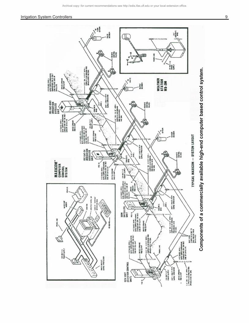
Telephone and serial links can be hardwired or wireless. Figure 9 shows the components of a typical high-end commercially available computer based control system.
ACTUATORS (AUTOMATIC VALVES)
Valves specifically designed for remote control are an important component of the irrigation control system. These type of valves are constructed using different materials. Typically brass, stainless steel and a wide array of plastics. Different valve actuation designs are used to operate the valves: 1) diaphragm type, 2) piston type, 3) and electric thermal motor type.
Diaphragm Valves
The most common type of automatic valve is the diaphragm type. In this type of valve a diaphragm is used to block the passage of water through the valve. The diaphragm is moved from an closed to open position by using the action of a spring and water
pressure differences. The design of the valves is such that pressure differences can be manipulated using a solenoid assembly with an actuator or a hydraulic pressure tubing.
Electric solenoid diaphragm valves
In an electric solenoid valve in the closed position, the pressure of the water in the chamber above the diaphragm (Figure 10) is the same as in the pipe at the entrance of the valve. Because the positive action of the spring and the lower pressure on the outlet, there is a force acting down on the diaphragm that pushes the seating disc against the body seat. If water is allowed to "leak" from the chamber above the diaphragm to the downstream end of the valve, the pressure in the chamber will decrease, allowing the pressure on the inlet side (below the diaphragm) of the solenoid valve to push the diaphragm against the spring with enough force to compress it, causing the valve to open. The valve will remain open as long as there is leakage from the upper chamber into the downstream end of the valve. When the solenoid is deactivated and the plunger obstructs the exhaust passage, water flows into the chamber through the inlet pressure orifice until the pressure in the chamber is equal to the pressure of water at the inlet. Because the spring provides a positive action and the force due to the pressure difference is decreased, the valve closes. As the downstream pressure drains, the pressure downstream decreases even more, providing a pressure difference that further tightens the seal between the seating disk and the body seat.
Electric diaphragm valves are subject to very little wear and require little maintenance. They are very economical, particularly in small sizes. They seldom leak because the seat disk is molded into the diaphragm and they do not require packing (such as the packing required in valves that have a stem). Operation problems in these types of valves are usually related to blocked pressure inlet and exhaust orifices, sticky plungers, faulty solenoids, and (were very dirty water is used) debris between the seating disc and the body seat.
Archival copy: for current recommendations see http://edis.ifas.ufl.edu or your local extension office.
����������������������������� $
Archival copy: for current recommendations see http://edis.ifas.ufl.edu or your local extension office.

����������������������������� %&
Hydraulically activated diaphragm valves
This type of valve functions in a manner very similar to the electrically activated diaphragm pump. However, in this type of valve, the pressure in the chamber is controlled by a small diameter line that is in turn connected to a pressure source using a hydraulic switching device. The switching device uses the small diameter line to relieve pressure in the chamber resulting in the valve opening, or to apply pressure, resulting in the valve closing.
Another method used is to connect the chamber to the main supply line using a small tube. Then a pilot valve is used to bleed the chamber allowing the pressure in the line to open the valve. To close the valve the pilot valve reconnects the hydraulic control line to the main supply, pressurizing the chamber and causing the valve to close (See Figure 11 ).
Hydraulic control systems require that water used in the hydraulic system be clean to prevent clogging of the pilot valves and the control lines. Also, hydraulic control lines must be protected where there is a danger of freeze.
Piston Valves
These valves employ a moving piston to open and close valves. Their operation is similar to diaphragm valves in that they are operated by pressure differentials. These valves are problematic because they incorporate O-rings or leather cup washers. Leather cup washers tend to dry out. O-rings tend to wear and stick after long periods of non-use.
Electric Thermal Motor Valves
These valves use a thermal motor to directly operate the valve.
Pump Start
With the exception of those situations where pressurized water is readily available, in addition to activating valves, the control system must have the capacity to activate the pump unit. Electric motor driven pumps can be activated using a pumpstart relay that is activated by the computer. This feature is available in most low-cost irrigation timers. Startup
Archival copy: for current recommendations see http://edis.ifas.ufl.edu or your local extension office.

����������������������������� %%
systems are also available for internal combustion power units.
For small or intermediate systems, depending on location of the pump station, an air tank with a pressure switch can be used to start the pumping station. In this way the pump motor will respond to a drop of pressure in the system due to a valve opening. These types of systems are especially useful where the flow demand varies.
WIRING
Wiring of an irrigation control system should be done by a competent professional to insure that safety requirements are met and that the system meets the necessary codes. Most problems with irrigation controllers can be traced to poor electrical installation, particularly lack of adequate grounding. Wherever electronic components are used it is important that attention be paid to signal and powerline protection.
Archival copy: for current recommendations see http://edis.ifas.ufl.edu or your local extension office.