residential and commercial irrigation system controller … tmc-… · · 2008-05-12residential...
TRANSCRIPT

TMC-212TM
Residential and Commercial Irrigation System Controller
User’s Guide

Congratulations! You have chosen one of the mostsophisticated and technologically advanced irrigationsystem controllers available for residential and light-commercial applications.Your new Toro TMC-212 controller features:
Flexible Station Count from 2 to 12 Stations with2-station Expansion modules
Standard and High-surge Expansion ModulesLocking Outdoor CabinetAutomatic Pump Start/Master Valve Control Circuit365-day Calendar3 Fully-independent Watering Programs
4 Start Times per Watering Day3 Watering day Schedule Options:7-day Calendar7-day Interval with Day ExclusionOdd/Even Days with Day ExclusionStation Time from 1 minute to 4 hoursPump Start/Master Valve Timing ControlWell Recovery/Station Delay Time
Season Adjust from 10 to 200 %Rain Delay from 17 DaysAutomatic Program/Start Time StackingRain Sensor Ready
Compatible with All Rain Sensor TypesSensor Circuit Bypass Switch
Remote Control ReadyAutomatic Circuit Protection - Eliminates FuseNon-volatile Program Memory - Eliminates Battery
The TMC-212 has some unique features and operatingcharacteristics. Take just a few minutes to browsethrough this manual and familiarize yourself with theTMC-212 components, installation requirements andoperating features.
The User’s Guide is divided into six main sections:
• The first section provides a brief description of the controller components and display elements.
• The second section takes you step-by-step through the installation process.
• The next section provides fundamental irrigation system operation, basic controller operation as well as specific programming and operating characteristicsof the TMC-212.
• The fourth section takes you step by step through theprogramming process.
• The fourth section explains the various methods ofautomatic and manual controller operations.
• An appendix provides various reference information,specifications and warranty information.
A watering schedule form (affixed to the cover of the outdoor model cabinet and included on page 20 of theUser’s Guide for the indoor model) provides a convenientplace to record the location of each watering station areaand specific details of your automatic watering programs.

Controller Components ...................................2
Controller Installation ■ Indoor Model Installation ................................6
❚ Connecting the Valves ....................................7❚ Connecting a Pump Start Relay......................8❚ Connecting the Transformer ...........................8
■ Outdoor Model Installation .............................9❚ Preparing the Cabinet for Installation..............9❚ Installing the Cabinet.....................................10❚ Connecting the Valves ..................................11❚ Connecting a Pump Start Relay....................12❚ Connecting the Power Source ......................13
■ Connecting a Rain Sensor...............................13
Getting Started ■ Irrigation System Basics ..................................14■ Watering Program Basics ................................15■ Watering Program Details................................16■ Planning Your Watering Schedule...................18■ Filling Out the Watering Schedule Form..........18
❚ Watering Schedule Form ..............................20
Programming the Controller■ About the Controller Memory...........................21■ Setting the Current Time and Day or Date ......21■ Setting the Watering Day Schedule.................22
❚ Setting a Calendar Schedule ........................22❚ Setting an Interval Schedule .........................23❚ Setting an Odd or Even Schedule.................24❚ Using the Day Exclusion Feature .................25
■ Turning Off a Program ....................................26■ Setting Program Start Times ...........................27■ Setting Station Times.......................................28■ Setting Pump/Master Valve and
Well Recovery Controls ...................................28
Controller Operations■ Automatic Mode ............................................30■ Manual Mode .................................................31
❚ Operate Watering Program(s).......................31❚ Operate Stations ...........................................31❚ Watering Control Features ............................32
❚ Pause Watering ..........................................32❚ Resume Watering .......................................32❚ Cancel Watering .........................................32❚ Skip Stations...............................................32❚ Adjust the Station TIme During Operation ..33
■ Rain Delay Feature..........................................33■ Season Adjust Feature ....................................34■ Turn Off Operation...........................................35
Appendix■ Clearing the Program Memory.........................36■ About Automatic Circuit Protection ..................37■ Adding a 2-Station Expansion Module.............37■ Using Pump/Master Valve Controls.................38■ Troubleshooting ...............................................40■ Specifications...................................................41■ Warranty ..........................................................42■ Electromagnetic Compatibility .........................42
Table of Contents
1

Controller Components
Controller Components
2

Controller Components
The following are brief descriptions of the controller com-ponents and display elements. Each of these items willbe explained in further detail within the appropriate pro-gramming, operating and installation sections of thisguide.
1 - LCD Display
A - “Start Time” symbol is displayed when setting theprogram start times.
B - “Well Recovery” symbol is displayed when wellrecovery time delay is in use.
C - Program start time identification numbers 1–4.
D - Main display of various time values and prompts.
E - Program A, B and C identifiers.
F - “Watering On” symbol is displayed when a water-ing station is running. Symbol blinks when wateringis paused.
G - “Watering Off” symbol is displayed when RainDelay feature is active.
H - “Percent” symbol is displayed when the SeasonAdjust feature is in use.
I - Watering Station identification numbers.
J - Day of the week identifiers.
K - “Run Time” symbol is displayed when setting thewatering station run times.
2 - Control Buttons
+/ON button – Increases the time display, scrolls for-ward through the program information and selectswatering days.
–/OFF button – Decreases the time display, scrollsbackward through the program information andremoves watering days.
NEXT button – Advances to the next portion of pro-gram information. Resumes watering if paused.Advances through stations manually when watering.
MANUAL START button – Selects and starts manualwatering operations.
3 - Control Dial – Selects all controller programmingand operation controls (except Manual Start).
Control Dial Positions
RUN – The normal dial position for all automaticand manual operations.
CURRENT TIME/DAY – Enables the clock timeand day to be set.
WATERING DAYS – Enables the watering dayschedules to be set and reviewed.
START TIMES – Enables the program start times tobe set and reviewed.
STATION TIMES – Enables the station run time tobe set and reviewed.
(continued)
3

Controller Components
3 - Control Dial Positions (continued)SEASON ADJUST – Enables the station time of allstations in a program to be simultaneouslyincreased or decreased in 10% increments.
SPECIAL FUNCTIONS – Provides optional controland timing features for pump operation and wellrecovery delay feature.
RAIN DELAY – Enables all watering operations tobe delayed from 1 to 7 days.
OFF – Shuts off and prevents all automatic andmanual watering activity.
4 - Program Select Switch – Three-position slideswitch used to select watering program A, B or Cduring the programming procedures and manualoperation.
5 - Rain Sensor Circuit Control Switch – Enables theRain Sensor circuit to be bypassed as necessary.
6 - Rain Sensor Configuration Switch – Configuresthe controller for operation with a Normally-open ora Normally-closed rain sensor.
7 - Rain Sensor Connection Terminals – Snap-in wire connectors for direct connection of a Rain Sensor.
8 - Valve Common Connection Terminal – Snap-inwire connector for the valve common wire.
9- Pump/Master Valve Connection Terminal – Snap-in wire connector for connection of a pumpstart relay or master valve 24 VAC power wire.
10 - Transformer Connection Terminals – Snap-inconnectors for transformer wires.
11 - 2-Station Expansion Module – Each 2-stationexpansion module provides connections for two irrigation control valves. Up to 6 modules for a totalof 12 stations can be installed. Provides 1.3 Kvsurge protection on each output.
12 - Remote Control Receiver Jack – Modular jackprovided for the connection of an optional Toro Remote Control receiver cable. (Installation and operating instructions are providedwith the Toro Remote Control system.)
13 - External Transformer – A Plug-in transformer sup-plies 24 VAC power for the indoor controller models.
14 - Internal Transformer – A built-in transformer supplies24 VAC power to the outdoor controller models.
15 - Input Power Terminal Block – Connection termi-nals for AC power wires.
16 - High-surge 2-station Expansion Module – Each 2-station expansion module provides connectionsfor two irrigation control valves. Up to 6 modules fora total of 12 stations can be installed. Provides 6.0 Kv surge protection on each output. Note: This module can only be used in high-surgeoutdoor controller models.
4

5
Controller Components

CAUTION: TMC-212 indoor controller models arenot weather resistant and must be installed indoorsor in a protected location.
1. Select a location for the controller within 4' (1.2m) ofan electrical outlet to enable the transformer wires toeasily reach. Make sure the outlet is not controlled bya light switch.
2. Remove the mounting bracket attached to the back of the controller housing by pulling the lower edge ofthe bracket away and downward from the controllerhousing.
3. Place the mounting bracket (A) against the wall align-ing the top edge at about eye level. Drive three 1" (25mm) wood screws (B) into the wall through thethree holes provided in the bracket.
Note: If you are installing the bracket on drywall ormasonry, install screw anchors (C) to prevent screwsfrom loosening.
4. Optional - Insert 3/4" (19mm) PVC conduit (D) forvalve wiring into bracket sleeve (E).
5. Align the slotted openings on the back of controllerhousing with the mounting bracket tabs. Slide thecontroller downward to engage the tabs.
Note: After installation, store the Quick ReferenceGuide and the Watering Schedule Form in the pocket (F) behind the controller.
Indoor Model Installation
Controller Installation
6
B
C
F
A
E
D
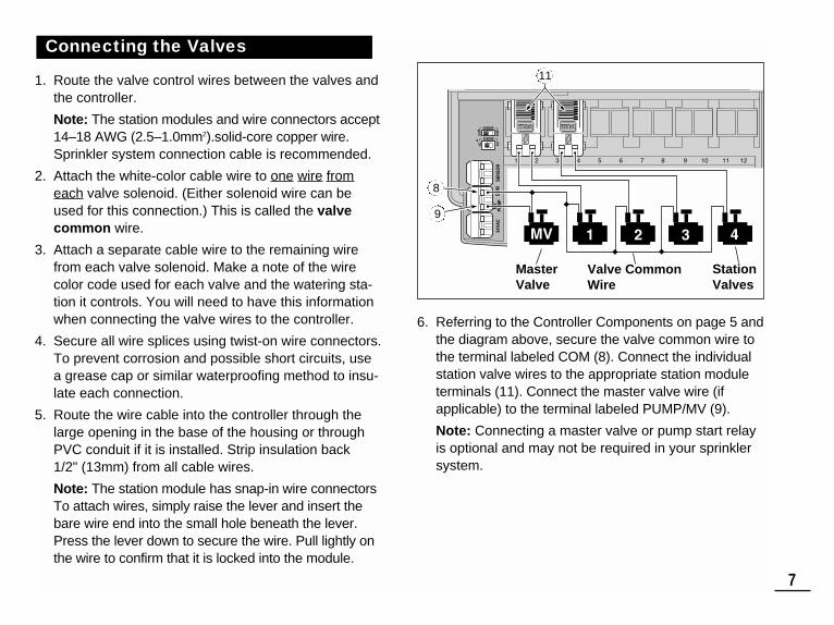
1. Route the valve control wires between the valves andthe controller.
Note: The station modules and wire connectors accept14–18 AWG (2.5–1.0mm2).solid-core copper wire.Sprinkler system connection cable is recommended.
2. Attach the white-color cable wire to one wire fromeach valve solenoid. (Either solenoid wire can beused for this connection.) This is called the valvecommon wire.
3. Attach a separate cable wire to the remaining wirefrom each valve solenoid. Make a note of the wirecolor code used for each valve and the watering sta-tion it controls. You will need to have this informationwhen connecting the valve wires to the controller.
4. Secure all wire splices using twist-on wire connectors.To prevent corrosion and possible short circuits, usea grease cap or similar waterproofing method to insu-late each connection.
5. Route the wire cable into the controller through thelarge opening in the base of the housing or throughPVC conduit if it is installed. Strip insulation back 1/2" (13mm) from all cable wires.
Note: The station module has snap-in wire connectorsTo attach wires, simply raise the lever and insert thebare wire end into the small hole beneath the lever.Press the lever down to secure the wire. Pull lightly onthe wire to confirm that it is locked into the module.
6. Referring to the Controller Components on page 5 andthe diagram above, secure the valve common wire tothe terminal labeled COM (8). Connect the individualstation valve wires to the appropriate station moduleterminals (11). Connect the master valve wire (ifapplicable) to the terminal labeled PUMP/MV (9).
Note: Connecting a master valve or pump start relayis optional and may not be required in your sprinklersystem.
Connecting the Valves
7
ENB
DIS
NONC
Valve CommonWire
StationValves
MasterValve
11
8
9

CAUTION: Never connect an auxiliary pumpstarter directly to the controller. A 24 VAC relay,rated at 0.30A maximum current draw, must be usedto connect the controller to the pump starter circuit.
1. Route a wire pair from the pump start relay into the controller housing.
2. Connect one wire to the valve common COM (8).Connect the remaining wire to the PUMP/MV (9) asshown below.
CAUTION: If the pump does not have an auto-matic pressure control switch, prevent pump damagedue to “dead-heading,” by connecting a jumper wirefrom any unused station terminal to a station terminalwith a valve wire connected.
Note: Refer to “Pump Control and Well Recovery” sectionon page 28 for important pump circuit control information.
CAUTION: Do not plug the transformer into anelectrical outlet until all of the wiring procedures havebeen completed.
1. Route the cable from the transformer (13) through the small opening provided in the base of the housing.Wrap the cable around and through the restraining postas shown below.
2. Connect one transformer cable wire to each terminallabeled 24 VAC (10). The wires can be connected toeither terminal.
Note: The display will begin flashing 12:00 a.m. Pressany button to stop the display from flashing.
Connecting the Plug-in TransformerConnecting a Pump Start Relay
8
1 2 3 4 5 6 7 8 9
9V
24 VAC Pump Start Relay Valve Common Wire
Jumper Wire8
9
10
13

1. Remove the lower housing cover (A) by pulling outward on the handle.
2. Remove two phillips screws from the transformeraccess cover (B). Pull the cover outward from the bottom to remove.
3. Three lower mounting holes (C) are provided. Thecenter hole is open and the outer holes are plugged.If you intend to use the outer holes for installation,carefully drill through the plugs with a 3/16" (5mm)drill bit.
Four wiring access holes are provided in the cabinetbase as follows: (D) - 1/2" (13mm) for power and equipment ground wires.(E) - 1/2" (13mm) (plugged) for optional Toro Rain
Sensor wires.(F) - 3/4" (19mm) for sprinkler valve wires.(G) -1/2" (13mm) (plugged) for optional Toro remote
control cable.4. If planning to install the optional Toro components,
remove the plugs as necessary.
Outdoor Model Installation
Preparing the Cabinet for Installation
9
MANUALSTART
ON
NEXT
OFF
MANUALSTART
ON
NEXT
OFF
A
B
C
FED G

1. For safe, reliable operation, select an installation sitewhich will provide the following conditions:• Protection from irrigation spray, exposure to direct
sun during the hottest hours, wind and snow.• Access to a grounded power source which is not
controlled by a light switch or utilized by a high current load appliance, such as a refrigerator or airconditioner.
• Access to the sprinkler control valve wiring andoptional accessory wiring.
2. Drive a wood screw (provided) into the wall at eyelevel (A). Leave the screw extended approximately1/4" (6.5mm) from the wall.
Note: If you are installing the controller on drywall ormasonry, install screw anchors to prevent screwsfrom loosening. Use the dimension shown to predrillholes for screw anchors.
3. Hang the cabinet on the screw using the keyhole slot (B) on the back panel. Make sure the cabinetslides down securely on the screw.
4. Install the lower mounting screw(s) and tightensecurely.
Note: Conduit and adapters are not provided. Installconduit as required by local electrical codes.
5. Install 1/2" (13mm) conduit (C) for power/equipmentground wires and 3/4" (19mm) conduit (D) for valvewires.
Note: After installation, store the User’s Guide andQuick Reference Guide on the hook located on theinside of the door.
Installing the Cabinet
10
6" (15.24cm)
BA
DC

11
Note: Using 16 to 18 AWG (1.5mm2 to 1mm2) irrigationcable is recommended. This cable is made specifically forautomatic irrigation systems and is available in severallengths and conductor count. Always use a cable that hasat least one wire for each valve and one wire for the valvecommon connection.1. Route the wire cable from the valve location into the
controller cabinet.
2. Attach the white color-coded cable wire to one wirefrom each valve solenoid. This is called the valvecommon wire.
Note: The solenoid does not have specific polarity, so either wire can be used for the common wire connection).
3. Connect an individual color-coded cable wire to theremaining solenoid wire of each valve. Make a notethe wire insulation color used for each valve connec-tion and the sprinkler zone controlled by the valve.
IMPORTANT: Properly insulate and waterproof allsolenoid wire connections and cable wire splices toprevent short circuit conditions.
4. Remove 1/2" (13mm) of insulation from the end of allcable wires to be connected to the controller.
IMPORTANT: The TMC-212 has snap-in wire termi-nals. To attach wires, simply raise the lever, insert thestripped end of the wire, then press the lever down tosecure the connection. After securing a wire, inspect theconnection to verify a small portion of bare wire is visibleto ensure that insulation is not present in the wire contactarea.
5. Referring to the Controller Components on page 5 andthe diagram above, secure the valve common wire tothe terminal labeled COM (8). Connect the individualvalve wires to the appropriate expansion module ter-minals (11). The stations are numbered from left toright, 1 through 12. Connect the master valve wire (if applicable) to the terminal labeled PUMP/MV (9).
Connecting the Valves
Valve Common Wire StationValves
MasterValve
11
8
9

CAUTION: To prevent controller damage, neverconnect an auxiliary pump starter directly to the controller’s 24 VAC output. A 24 VAC 0.30A relay,must be used to connect the controller to the pumpstarter circuit.
1. Route a wire pair from the pump relay into the con-troller housing.
2. Connect one wire to the terminal labeled COM (8).Connect the remaining wire to the terminal labeledPUMP/MV (9) as shown below.
CAUTION: To prevent pump damage due to pro-longed dead-head pressure, connect a jumper wirefrom an unused station terminal to a terminal with awith a valve connected.
Note: Refer to “Pump Control and Well Recovery” sectionon page 28 for important pump circuit control information.
1. Route the power and equipment ground wires from thepower source, through the conduit and into the con-troller transformer compartment.
Note: The controller terminal block accepts wire sizeup to 12 AWG (4mm2).
2. Remove 3/8" (10mm) insulation from the wire ends.
3. Using a small flat blade screwdriver, secure the wiresas shown to the terminal block as follows:Line or Line 1 (L1) to L, Neutral or Line 2 (L2) to Nand Equipment Ground to .
4. Install and secure the transformer compartmentcover.
5. Apply power to the controller.
Note: The display will begin flashing 12:00 AM. Press anybutton to stop the display from flashing.
Connecting the Power SourceConnecting a Pump Start Relay
12
Pump StartRelay
Valve Common Wire
Jumper Wire
WARNING:AC power wiring must be installed and connectedby qualified personnel only. All electrical compo-nents and installation procedures must complywith all applicable local and national electricalcodes. Some codes may require a means of discon-nection from the AC power source installed in thefixed wiring and having a contact separation of atleast 0.120" (3mm) in the line and neutral poles.
Make sure the power source is OFF prior to con-necting the controller.
8
9

A rain sensor is an optional control device that connectsdirectly to the TMC-212 to automatically interrupt auto-matic controller operation during rain.A sensor bypass switch is provided to enable sensoroperation to be disabled as needed.A sensor configuration switch enables the controller to workwith a normally-open or a normally-closed rain sensor.When the rain sensor absorbs moisture it signals theTMC-212 to suspend automatic watering operations. The “No Watering” symbol is displayed until the sensordrys out and automatically resets. The symbol will disappear and controller operation will resume as programmed.
1. Route the sensor wires from the device into the con-troller housing through the access hole provided.
2. Remove the plastic insert from the Sensor terminal con-nectors. Connect sensor wires per the instructions pro-vided with the device.
3. Set the Sensor Configuration Switch (5) to NC(Normally Closed) or NO (Normally Open) operation as required by the type of sensor connected.
4. Set the Sensor Control Switch (6) as required: ENB(enable) allows the rain sensor to interrupt watering;DIS (disable) bypasses the rain sensor input.
IMPORTANT: Do not use the ENB switch posi-tion with the NC switch position unless a normally-closed rain sensor is connected. Watering operationwill be suspended if this condition occurs.
5. Refer to the instructions provided with the rain sensorfor operating information.
Connecting a Rain Sensor (optional)
Connecting the Power Source (cont.)
13
5
6
Toro WirelessRain Sensor
5
6

The three major components of every automatic sprin-kler system are the controller, the control valves and thesprinklers/emitters. The controller is the brain of the system, signaling eachcontrol valve when and how long to open. The valves areconnected to numbered terminals within the controller,and identified as Station 1, Station 2, etc. Each stationcontrols a group of sprinklers in a specific portion of thelandscape called a watering “Zone.” The zones are gen-erally laid out according to the type of plant materialbeing watered and the type and flow rate of the sprin-klers used to distribute the water.Automatic controller “Programs” are used to establishand organize different watering schedules. The TMC-212provides three independent watering programs, desig-nated A, B and C. and are established by specifying:what day(s) of the week to water – called watering days,what time to start watering – called start time and howlong each station runs – called station time. Each station can be assigned to each program and havea different amount of run time in each program.When an automatic program starts, each station with anassigned run time in the program will operate one by onein numeric sequence from lowest to highest station num-ber
Getting Started –Irrigation System Basics
14
Valve 1 - Station 1 - Parkway Lawn - Fixed Spray
Valve 2 - Station 2 - Front Lawn - Fixed Spray
Valve 3 - Station 3 - Front Shrubs - Flood Bubbler
Valve 4 - Station 4 - Back Lawn - Geared Rotor
Valve 5 - Station 5 - Garden - Drip
Valve 1Controller
Valve 2
House
Valve 3
Valve 4
Valve 5

The following example illustrates how a typical wateringprogram could be set up for the sprinkler system shownon the previous page.The diagram at the right depicts the watering program ina timeline format. Example: The program start time is set for 3:00 a.m.Lawn stations 1 and 2 each have a run time of 10 min-utes and lawn station 4 is set to run for 20 minutes. Notethat stations 3 and 5 water shrubs and flowers and havebeen excluded from this program. (These stations will beset to operate on a separate program).As shown in the watering program diagram, at 3:00 a.m.the controller starts the program watering cycle. Station 1 sprinklers run for 10 minutes and shut off. Next,station 2 sprinklers turn on, run for 10 minutes and shutoff. The controller skips station 3, and turns on station 4which runs for 20 minutes and shuts off. Station 5 isskipped and the watering cycle ends at 3:40 a.m.
As you can see from this example, only one programstart time was needed to operate three different stations.
Using more than one program for example, would enablelawn zones to be watered every day on program A,shrub zones to run on on Monday, Wednesday andFriday on program B and drip irrigation to soak theflower beds every three days on program C.
Note: Although the TMC-212 offers the multiple programfeature, you may want to use one program only if itmeets your needs. The remaining programs can beturned off and on as you need to use them.
Watering Program Basics
15
3
12
9
6
3
12
9
6
3
12
9
6
Station 1Station time10 minutes
Station 2Station time10 minutes
Station 4Station time20 minutes
Program Startsat 3:00 a.m.
Program Endsat 3:40 a.m.
Watering Program Diagram

16
This section covers in detail each of the three parts of awatering program: watering days, program start timesand station times.
Selecting a Watering Day Schedule
The TMC-212 provides three optional formats for schedul-ing watering days: Calendar, Interval, Odd or Even. The Calendar FormatThe Calendar format is a recurring 7-day schedule thatbegins on Sunday and enables you to select specificdays of the week to water.
This illustration shows how a Calendar schedule would be dis-played when the control dial is in theWATERING DAYS position. In this example, program A has watering days set forMonday (MO), Wednesday (WE) and Friday (FR).
The Interval FormatThe Interval format provides a periodic watering dayschedule ranging from 1 (every day) to 7 (every-7th day)in one-day increments. For example, to water every thirdday, you would select a 3-day interval. Since the interval schedule is not tied to specific days ofthe week, you will need to determine when the intervalwill start by selecting the initial watering day.
For example, if you have selected a 3-day Interval andtoday is Sunday, you may choose to have the first day ofthe Interval on Sunday, Monday or Tuesday. From thatpoint on, two days will be off and the third day will water.
This illustration shows how an Interval schedule would be displayed.In this example, program B has a 3-day Interval schedule set to beginon Monday.
Odd/Even FormatThe Odd/Even format enables you to select all odd or alleven numbered days of the month as watering days.
This illustration shows how anOdd day schedule would be displayed.
Day Exclusion FeatureSince the Interval and Odd/Even watering day formatsare not tied to actual calendar days, the Day Exclusionfeature enables you to prevent specific days of the weekfrom watering. For example, due to water conservationrestrictions, watering is not permitted on Monday. Also,the lawn is mowed on Friday, so Friday is also excluded.
This example shows the days exclud-ed (dE) are Monday and Friday in watering program A.
Program OffSelecting OFF suspends the operation of the programwhen it is not needed. Turning the program off does notalter or erase the program information.
This illustration shows how a program would be displayed if isturned off. In this example, programC is off.
Watering Program Details

Selecting Program Start TimesA program start time is the time of day an automaticprogram watering cycle is set to begin. Sometimes it isnecessary to run a watering program more than one timeper day, for example, when establishing a new lawn.The TMC-212 enables each watering program (A, B andC) to have four independent start times.
Please note the following start time conditions:• A watering program requires only one start time tooperate automatically.
• A start time is assigned to a watering program, not toan individual station.
• When a start time occurs, the stations with operatingtime assigned in the program will be operated one at atime (for their set duration) in numeric sequence.
• If a program start time occurs while the controller isalready running a watering cycle, the start will bedelayed until the current watering cycle concludes (thisis known as “Stacking”).
Program start times are displayed as 1 through 4. Thesenumbers are shown at the top left of the display next tothe start time symbol when the control dial is in theSTART TIME position.
This illustration shows how aprogram start time is displayed.In this example, program Ahas one start time (start timenumber 1) set for 3:00 a.m.
Setting the Station Time
Station time is the amount of time a station’s control valvestays open during a watering cycle. Station time can be setfrom 1 minute to 4 hours (in 1-minute increments).
When setting a station time, the first step is to select awatering program. When a station is given a time of atleast 1 minute, it is assigned to the program. A station isremoved from a program by setting it’s time to “Off.”
Each station can have a time assignment in each program.For example, station 1 could be set to run for 15 minutes inprogram A, 10 minutes in program B and Off in program C.
All stations assigned to the program are shown on thelower portion of the display when the control dial is in theSTATION TIMES position.
The run time symbol is displayed when station time isbeing set. The displayed time is assigned to the flashingstation number.
This example shows how station time is displayed.Stations 1, 2 and 4 are assignedto program A. Station 1 and 2are set for 10 minutes and station 4 is set for 20 minutes. Stations 3, 5 and 6 are not dis-played because they do nothave an assigned time in program A.
17
Flashing
Flashing
Flashing

18
It is always helpful to have your initial watering scheduleorganized on paper before beginning the programmingsteps. The information can be recorded on the WateringScheduling form located inside the cover of the outdoorcontroller or on the blank form provided on page 20.
Guidelines for Watering There are several factors to considered when determin-ing how much to water. For example, the soil composi-tion, the type of lawn and plants, exposure to sun andshade and the rate at which the sprinklers apply water.Because of these variables, an exact schedule can notbe provided. Some trial and error will be required to findthe best watering schedule, but here are some generalwatering guidelines to help you get started.
• Water two or three hours before sunrise. You will havethe best water pressure at this time and evaporationwill be minimal.
• With a new lawn, water frequently for a short durationto keep the soil and plants moist at all times untilestablished. Cut back on watering if runoff occurs.
• With an established landscape, water enough to saturate the plants and soil without causing runoff.Gradually cut back watering over a period of time untilyou notice signs of plant stress. Increase wateringgradually just enough to regain plant health and vitality.This watering method enables a healthy landscape tobe maintained using the least amount of water.
Filling Out the Watering Schedule Form
• Location - Identify the portion of the landscapewatered by each station. Note: Enter the following information for each program(A, B and C). If a program is not needed, leave itsinformation column blank.
• Watering Day Schedule - For a Calendar schedule,circle the day(s) of the week watering is desired. Foran Interval schedule circle the desired Interval num-ber. For Odd or Even days, simply mark the appropri-ate box. If you need to restricted watering on certaindays, circle the excluded day(s).
• Station Time - Indicate the amount of operating time (1 minute to 4 hours) for each station. Write “Off” for anystation which you do not want to assign to the program.
• Well Recovery Delay Time - Well recovery time isindicated her. See “Pump Control and Well Recovery”on pages 28 and 29 for detailed information.
• Program Start Times - Indicate the time of day tostart the program. Each program can have up to 4separate start times.Note: The TMC-212 can operate only one program at a time. Within that program, only one station canoperate at a time. Therefore, when using more thanone program or using more than one start time in aprogram, make sure that each watering cycle can runto completion before the next watering cycle starts. Astart time that occurs while a watering cycle is alreadyin progress will be delayed until the active wateringcycle is finished. If the start time is delayed past Mid-night into the next day, the start will be ignored if theday is not scheduled as an active watering day.
Planning Your Watering Schedule

19
SU MO TU WE TH FR SA SU MO TU WE TH FR SA SU MO TU WE TH FR SA
MOSU TU WE TH FR SA SU MO TU WE TH FR SA SU MO TU WE TH FR SA
1 2 3 4 5 6 7 1 2 3 4 5 6 7 1 2 3 4 5 6 7
CALENDAR
LOCATION
WELL RECOVERY DELAY TIME
STATION RUN TIME STATION RUN TIME STATION RUN TIME
WATERING DAY SCHEDULE
INTERVAL
EXCLUDE
ODDODD/EVEN EVEN
PROGRAMSTART TIMES
1
2
3
4
PROGRAM AWatering Schedule Form PROGRAM B PROGRAM C
ODD EVEN ODD EVEN
123456789
101112
STATION
Parkway LawnFront LawnFront ShrubsBack LawnGarden
1010Off
Off OffOff
OffOff Off
OffOffOff25
20
1 hr
2:30 am 4:00 am 5:00 amOffOff
Off OffOffOffOff
OffOff
10
(Example)

20
SU MO TU WE TH FR SA SU MO TU WE TH FR SA SU MO TU WE TH FR SA
MOSU TU WE TH FR SA SU MO TU WE TH FR SA SU MO TU WE TH FR SA
1 2 3 4 5 6 7 1 2 3 4 5 6 7 1 2 3 4 5 6 7
CALENDAR
LOCATION
WELL RECOVERY DELAY TIME
STATION RUN TIME STATION RUN TIME STATION RUN TIME
WATERING DAY SCHEDULE
INTERVAL
EXCLUDE
ODDODD/EVEN EVEN
PROGRAMSTART TIMES
1
2
3
4
PROGRAM AWatering Schedule Form PROGRAM B PROGRAM C
ODD EVEN ODD EVEN
123456789
101112
STATION

About the Watering Program MemoryOnce programmed, the TMC-212 memory will beretained for several years without power. Only the cur-rent time and date information will be lost and will needto be reset if power is interrupted from the controller formore than 24 hours. The TMC-212 has a permanent (default) watering programthat will automatically control your sprinkler system whenpower is lost.The default settings are as follows:
• Program A has a Calendar watering schedule set towater every day. Programs B and C are turned Off
• One program start time set for 5:00 a.m.• Station time set to 10 minutes per station • Pump Start/Master Valve circuit is On.• Pump Start/Master Valve circuit delay is 2 seconds• Well Recovery time is 0 seconds.• Pump Start/Master Valve circuit is enabled during Well
Recovery time.• Season Adjust is 100%If you do not wish to program the controller, you canuse the default settings as is. To enable the TMC-212controller to operate Automatically in real time, setthe current time, day and date.
Note: The controller’s programmable memory can be resetto the default settings at any time. See “Clearing the Pro-gram Memory” on page 36 for detailed information.
Turn the control dial to the CURRENT TIME/DAY
position (the hour digits will begin flashing).
Note: The time of day will be displayed in hours andminutes (12-hour format). To select a 24-hour format,press the next button repeatedly to display 12 H. Pressthe +/ON button to display 24 H. Press the next buttononce (the hour digits will begin flashing).
To increase the display value, press the +/ON button;to decrease, press the –/OFF button.
Note: The display characters will change rapidly whenholding the +/ON or –/OFF button down for more than twoseconds.
Press the NEXT button to select the next portion ofthe display.
4. Repeat steps and to set the following currentinformation: minutes, year, month and day.
When the current time and day are displayed, returnthe control dial to the RUN position.
Setting the Current Time and DateProgramming the Controller
21
5Day
Month
22
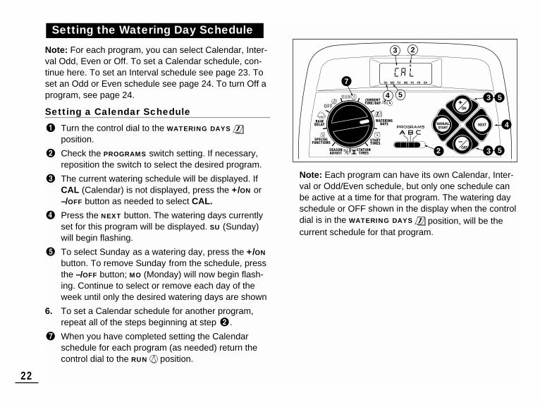
Note: For each program, you can select Calendar, Inter-val Odd, Even or Off. To set a Calendar schedule, con-tinue here. To set an Interval schedule see page 23. Toset an Odd or Even schedule see page 24. To turn Off aprogram, see page 24.
Setting a Calendar Schedule
Turn the control dial to the WATERING DAYS
position.
Check the PROGRAMS switch setting. If necessary,reposition the switch to select the desired program.
The current watering schedule will be displayed. IfCAL (Calendar) is not displayed, press the +/ON or–/OFF button as needed to select CAL.
Press the NEXT button. The watering days currentlyset for this program will be displayed. SU (Sunday)will begin flashing.
To select Sunday as a watering day, press the +/ON
button. To remove Sunday from the schedule, pressthe –/OFF button; MO (Monday) will now begin flash-ing. Continue to select or remove each day of theweek until only the desired watering days are shown
6. To set a Calendar schedule for another program,repeat all of the steps beginning at step .
When you have completed setting the Calendarschedule for each program (as needed) return thecontrol dial to the RUN position.
Note: Each program can have its own Calendar, Inter-val or Odd/Even schedule, but only one schedule canbe active at a time for that program. The watering dayschedule or OFF shown in the display when the controldial is in the WATERING DAYS position, will be thecurrent schedule for that program.
Setting the Watering Day Schedule
7
4
5
23
3 5
354

23
Setting an Interval Schedule
Turn the control dial to the WATERING DAYS
position.
Check the PROGRAMS switch setting. If necessary,reposition the switch to select the desired program.
The current watering schedule will be displayed. IfInt (Interval) is not displayed, press the +/ON or–/OFF button as needed to select Int.
Press the NEXT button. The current Interval number(1–7) will begin flashing. The day of the week onwhich the Interval will start will be shown.
To change the Interval number, press the +/ON or–/OFF button until the desired number is flashing.
Press the NEXT button. The Interval start day willbegin flashing.
To change the Interval start day, press the +/ON
button or the –/OFF button until the desired day isflashing.
8. To set an Interval schedule for another program,repeat all of the steps beginning at step .
When you have completed setting the Intervalschedule for each program (as needed), return thecontrol dial to the RUN position.
Note: The Day Exclusion feature enables you toselect any day(s) of the week to be excluded andremain off when using an Interval or Odd/Evenwatering schedule.See page 25 for detailed information.
7
6
23
9
4
7557 4
3 5
36
1

Setting an Odd or Even Schedule
Turn the control dial to the WATERING DAYS
position.
Check the PROGRAMS switch setting. If necessary,reposition the switch to select the desired program.
The current watering schedule will be displayed. IfOdd or Even is not displayed, press the +/ON or–/OFF button as needed to select Odd or Even.
Note: When Odd is selected, the 31st day of themonth and the 29th day of a leap year will not beactive watering days.
4. To set an Odd or Even schedule for another program, repeat steps and as needed.
When you have completed setting the Odd or Evenschedule for each program as needed, return thecontrol dial to the RUN position.
Note: The Day Exclusion feature enables you toselect any day(s) of the week to be excluded andremain off when using an Interval or Odd/Evenwatering schedule. See page 25 for detailed informa-tion.
24
23
5
3
3
1

Using the Day Exclusion Feature
A Calendar schedule is generally used to exclude orselect specific days of the week for watering. However, if an Interval or Odd/Even watering schedule is preferred(or required), the day exclusion feature enables you toselect any day(s) of the week to be excluded and remainoff regardless of the program schedule.
Note: The selected program must have an Interval orOdd/Even watering schedule to use the Day Exclusionfeature.
Turn the control dial to the WATERING DAYS
position.
Check the PROGRAMS switch setting. If necessary,reposition the switch to select the desired program.
The current watering schedule (Interval orOdd/Even) will be displayed. Press the NEXT buttonas needed to display d E. The days of the week willbe displayed and SU (Sunday) will begin flashing.
To exclude Sunday from the watering schedule,press the –/OFF button. To keep Sunday and skip tothe next day, press the +/ON button; MO (Monday)will now begin flashing. Continue to exclude or skipeach day of the week as needed.
Example: Tuesday and Friday have been excludedfrom program A.
When finished, return the control dial to the RUN
position.
25

Turning Off a Program
Note: Turning off a program does not alter or erase apreset watering day schedule. Selecting Off simplyplaces the program on hold until one of the watering dayformats is selected.
Turn the control dial to the WATERING DAYS
position.
Check the PROGRAMs switch setting. If necessary,reposition the switch to select the desired program.
Press the +/ON or –/OFF button until OFF is flashing.
4. To turn another program Off, repeat steps andas needed.
Return the control dial to the RUN position.
26
23
5
3
3
1

Turn the control dial to the PROGRAM START TIME
position.
Check the PROGRAMS switch setting. If necessary,reposition the switch to select the desired program.
Program start time number 1 will begin flashing. Thecurrent program start time or OFF will be displayedfor start time number 1. To select a different programstart time number, press the +/ON or the –/OFF but-ton until the desired number is flashing.
Note: The numbers (1–4) shown at the top of the displaydesignate program start times and should not be con-fused with station numbers. The station numbers will beshown at the bottom of the display when setting stationrun time.
Press the NEXT button. The hour digit(s) or OFF willbegin flashing.
Note: To remove the start time, select OFF bypressing the +/ON and –/OFF buttons at the sametime, and continue at step .
To set the hour (and AM/PM), press the +/ON or the–/OFF button until the desired hour is flashing.
Press the NEXT button. The minute digits will beginflashing.
To set the minutes, press the +/ON or –/OFF buttonuntil the desired minute is flashing.
Press the NEXT button. The next program start timenumber will begin flashing.
To select another start time number, press the +/ON
or the –/OFF button until the desired start time num-ber is flashing.
10. To set, change or remove a program start time forthe start time number selected, repeat all of thesteps starting at step .
11. To set program start times for another program,repeat all of the steps starting at step .
Return the control dial to the RUN position.
Setting Program Start Times
27
12
3 5 7 9
1
4 6 8
4 5 6 7
9 23
3 75 9

PGM A
1 2 3 4 5 6
3 5
3 5
9
4
3
5
21
42
5
Turn the control dial to the STATION TIMES
position.
Select Program A, B or C using the Program switch
Station number 1 will be flashing and its current sta-tion time or OFF will be shown. To select a different station number, press the +/ON or –/OFF button untilthe desired station number begins flashing.
Press the NEXT button. The station time (or OFF) willbegin flashing.
To change the station time, press the +/ON or –/OFF
button until the desired time is displayed.
Note: To reset the station time to Off, press the +/ON
and –/OFF buttons at the same time, or reduce thedisplayed time to one step past 0:01 minute.
Press the NEXT button. The next station number willbegin flashing.
7. Repeat steps and as needed to set, change,or remove the run time for the remaining stations.
8. To set the station run time for another program,repeat all of the steps starting at step .
Return the control dial to the RUN position.
Note: Basic programming is now complete. If the PumpStart/Master Valve circuit will be used to automaticallycontrol a master valve, auxiliary pump or a well waterirrigation supply, continue at “Setting Pump/Master ValveControls” on the next page.
The following timing control features enable the PumpStart/Master Valve (PS/MV) circuit and WellRecovery/Station Delay options to be set for each water-ing program as needed. (Defaults shown in parenthesis.)• PS/MV Circuit Master Switch (On)Enables/disables PS/MV circuit operation for the selectedprogram.
• PS/MV Circuit Delay Time (2 Seconds)The PS/MV circuit is switched on for 2 seconds prior to the first station starting in a program watering cycle.The delayed station start enables a pump or mastervalve to be fully operational before watering begins. The delay period is adjustable from two to 60 seconds.
• Well Recovery/Station Delay Time (0 Seconds)An adjustable duration from 0 seconds to 60 minutes that delays the start of each successive station during a watering cycle. The time delay between stations canenable a well or reservoir to maintain sufficient supplythroughout the watering cycle.
Setting Pump Start/Master Valveand Well Recovery Controls
Setting Station Times
9
3 5
1
4 5
3 5
542
28

• PS/MV Circuit Enabled During Well Recovery (Yes)This timing control feature enables the PS/MV circuit tobe active (Yes) or inactive (No) during a Well Recovery/Station Delay time period.
Note: Refer to Appendix A on page 40 for typical examplesof the PS/MV circuit and Well Recovery timing control features in use.
Turn the control dial to the SPECIAL FUNCTIONS
position. See Example 1.Check the PROGRAMS switch setting. If necessary,reposition the switch to select the desired program.
3. The display will show P On (Pump On) and willbegin flashing. To disable the PS/MV circuit operation for this program, press the –/OFF button; P OFF (Pump Off)will be displayed.Press the NEXT button to display the Pump Delaytime. Pd 02 (two-second delay) will be displayed. Press the +/ON or –/OFF button to select a delay time duration from 02 to 60 seconds.
Press the NEXT button to display the Well Recoverydelay time. The well recovery symbol and S 00(zero seconds) will be displayed. See Example 2.
Press the +/ON or –/OFF button to set the recovery or station delay duration from 02 to 60 seconds or 01 to 60 minutes. The display will change from S (seconds) to M (minutes) as the time is increasedpast 60 seconds.
Note: The well recovery symbol will be displayedwhen this timing control feature is used.(continued)
29
1
6
35
2
4
6
5
87
8
97
10
Example 2
Example 1
MinutesSeconds

Press the NEXT button to display the Pump Enableoption. PE Y (Pump Enable Yes) will be displayed.
Press the –/OFF to select PE n (Pump Enable No).See example 3.
To apply PS/MV circuit control features to anotherprogram, press the NEXT button once, then repeat
steps through .
When finished, return the control dial to the RUN
position.
The TMC-212 controller has three modes of operation:Automatic, Manual and Off.• Automatic mode – The controller tracks the current
time and day and automatically runs a watering programs when a scheduled start time occurs.
• Manual mode – Automatic watering programs or selectstations can be manually operated at any time.
• Off mode – Shuts off and prevents all watering activity.
In the Automatic mode, the TMC-212 keeps track of thecurrent time, day of the week and the automatic wateringprogram schedule. Automatic operation will occur when-ever a programmed watering day and start time matchthe current time and day.
The Automatic mode is selected when the control dial isin the RUN position. While in the automatic mode, thedisplay will show two types of information: Status andOperating.
This example shows the Status display. The current timeis 2:45 PM and the current dayis Monday. Programs A and Bare scheduled to operate today. When watering starts, the Operating display appears asshown with the Watering On symbol . In this example, program A isoperating. Station 1 has 10minutes of run time remaining.Stations 2 and 3 will also runduring this watering cycle.Well recovery time hasbeen set for program A.This program also has a season adjust factor, so thePercent symbol will be also displayed.
Note: If the control dial remains in any other position(except OFF) for more than 8 minutes, the controller willrevert to the Automatic mode.
(continued)
Automatic Mode
Controller Operation
30
Flashing
Flashing
12
11
11
10
10
Example 3

31
Note: The position of the PROGRAMS switch does notdetermine which program will run during automatic controller operation. In other words, if a program has anassigned watering day schedule, start time and a stationwith run time, it will operate automatically regardless ofthe position of the PROGRAMS switch.
Manual mode enables automatic watering programs andtheir assigned stations to be operated at any time.
Note: Once watering has started, see page 32 for addi-tional manual control operations.
Note: Upon completion of a Manual mode operation, thecontroller will return to the Automatic mode.
Operate Watering Program(s)
Confirm the control dial is in the RUN position.
Position the PROGRAMS switch to select a program.
Press the MANUAL START button two times to startthe program watering cycle. The first active stationnumber and the Watering On icon will begin flashing.
4. To select additional programs, repeat steps and .
Note: Additional programs are stacked (staged to run sequentially) in the order they are selected. The watering program identifier (A, B or C) will be displayed as each program is selected. The programcurrently operating is indicated by the flashing pro-gram identifier. As one program finishes the nextprogram in queue will start.
Operate Selected Stations
Confirm the control dial is in the RUN position.
Position the PROGRAMS switch to select a program.
Press the MANUAL START button one time.The station numbers assigned to the program will bedisplayed. The first station number in sequence willbegin flashing. To select the station(s) to operate,use the following procedure:• To select the station, press the +/ON button.• To skip the station press the –/OFF button.
When the desired station numbers are displayed,press the MANUAL START button one time to startwatering. The active station number and Watering Ondroplet icon will begin flashing.
Manual Mode
1
4
4
3 5
Flashing

Once the sprinkler system is running, the following man-ual control features become available:
Pause Watering
Press the +/ON and the –/OFF buttons at the same time.
• The station will temporarily turn off.
• The “Watering On” symbol will begin flashing.
• The display will show the amount of station time remaining.
Note: If watering is not resumed within 8 minutes, all watering operations will be canceled and the controller will return to the automatic mode.
To resume operation, press the NEXT button.
• Watering activity will resume from the point of interruption.
Cancel Watering
Two methods of canceling watering are available:
Press the +/ON and –/OFF buttons at the same time -two times.
• All watering operations will be canceled and the con-troller will return to the automatic mode.
Note: Placing the control dial in the OFF position fortwo seconds, then back to RUN willalso cancel all watering operations.
To Skip Stations:
Press the NEXT button one time.
• The station currently watering will shut off and thenext station will start.
• If the last station is skipped, the program will end. If additional programs have been set to operate, the next program in alphabetical order will start.
To Adjust the Station Run Time:
Press the +/ON button to increase run time or the –/OFF
button to decrease run time.
• If the station run time is decreased to less than 1 minute, the station will shut off. The next station in sequence will start.
• The station run time is changed during this operationonly. The program memory will not be changed.
Watering Control Features
32

33
Note: Rain Delay and Season Adjust control featuresenables quick, temporary changes in operation to helpcompensate for changes in weather and season.
This feature enables all watering operations to bedelayed from 1 to 7 days. For example, rain is forecast inyour area for the next two days. Instead of turning thecontroller off (and possibly forgetting to turn it back on), arain delay of 3 days can be easily entered. At the end of3 days, the controller will resume automatic operation asscheduled.
Turn the control dial to the RAIN DELAY position.The rain delay display will begin alternating with theautomatic status display.
To set the number of rain delay days, press the +/ON
or –/OFF button until the desired number (1–7) isflashing.
Return the control dial to the RUN position.
Note: The rain delay number will automaticallydecrease as each day passes. When the numberreaches 0 (zero), automatic operation will resume atthe next scheduled start time.
To cancel the rain delay, turn the control dialmomentarily (4 seconds) to the OFF position.
Rain Delay Feature
3
2
2
1
Flashing

Note: The Rain Delay and Season Adjust % featuresmodify controller operation only and do not alter the con-troller’s programmable memory.
The Season Adjust % feature enables the station time ofall stations (assigned to a watering program) to be simul-taneously decreased or increased from 10–200% in 10%increments.
For example, selecting a 50% factor decreases all sta-tions to half of their programmed station time. A stationprogrammed for 20 minutes would run 10 minutes and astation with 15 minutes would run 7 minutes and 30 sec-onds. As a conservation measure, an increase above100% time calculates the increased time and splits thetime in half. The program watering cycle then runsthrough twice consecutively. This method of increasingirrigation enables more water to soak into the plant rootzone instead of pooling and running off.
For example, adjusting to 150% will first increase a20-minute station time to 30 minutes (1.5 x 20 = 30). The controller automatically divides 30 minutes in halfand runs the station for 15 minutes in back-to-backwatering cycles.
Note: All station times are retained in the controller’s programmable memory and returned to their set valuewhen the season adjust is reset to 100%. The adjustedstation time will be displayed during operation. The % symbol will be displayed when an adjustment factor is in use.
Turn the control dial to the SEASON ADJUST
position. The season adjust display will be shownand 100% will be flashing.
Check the PROGRAMs switch setting. If necessary,reposition the switch to select the desired program.
Press the +/ON or –/OFF until the desired adjustmentvalue is flashing.
4. To apply the Season Adjust feature to another program, repeat steps and .
Return the control dial the RUN position.
Note: The Season Adjust symbol will be displayed inall dial positions as a reminder that this feature is in use.
Season Adjust % Feature
34
5
3
321

When the control dial is turned to the OFF position,controller operation stops immediately. Leaving the control dial in the OFF position enables the controllermaintain current time and day, while disabling automaticand manual watering activity.
Turn the control dial to the OFF position.
The word OFF will be displayed for approximatelyeight minutes. The display will then revert to theautomatic status display showing the current timeand day.
For extended shutdown of the sprinkler system leavethe control dial in the OFF position.
To resume automatic or manual operation, turn thecontrol dial to the RUN position.
Turn Off Controller Operation
35
2
1

Once programmed, the TMC-212 memory will beretained for several years with or without power. Only the current time and date will be lost and will need to bereset if power is interrupted for more than 24 hours.
The programmable memory can be cleared and reset to the default settings of individual programs or all programs simultaneously. (Refer to the default settings listed on page 21.)
IMPORTANT: This procedure permanently erasesthe programmable watering information and can not berestored once the procedure has been completed.
To clear the memory of a selected program (Example 1)
Turn the control dial to the SEASON ADJUST
position.
Check the PROGRAMS switch setting. If necessary,reposition the switch to select the desired program.Press the NEXT button to access the clear memoryfeature; CL will be displayed and begin flashing.Press and hold the –/OFF button until CL stops flash-ing (approximately five seconds). The memory willbe cleared to the default settings.
5. To clear the memory of another program, repeat allof the steps starting at step .
Return the control dial to the RUN position.
To clear the memory of all programs (Example 2)
Turn the control dial to the OFF position.
Press the NEXT button to access the clear memoryfeature; CL will be displayed and begin flashing.Press and hold the –/OFF button until CL stops flash-ing (approximately five seconds). The memory willbe cleared to the default settings. Return the control dial to the RUN position.
Clearing the Program Memory
Appendix
36
Example 1
Example 2

The TMC-212 features built-in circuit protection to helpprevent damage to the controller caused by excessivecurrent draw on the station and/or pump/master valve cir-cuits.
If the controller detects an over-load condition on a station, it willbypass the affected station(s) anddisplay the word FUSE with theaffected station number(s). All remaining stations willoperate as programmed for automatic operation.
If the condition occurs on thepump/master valve circuit, the controller will alternately displayMV and FUSE and discontinuethe program operation.
To clear the warning display,press the –/OFF button . The controller will continue tooperate as scheduled and will attempt to run all stationsas programmed.
IMPORTANT: Clearing the display does not correct the problem. The controller will continue to bypassthe affected station(s) or discontinue operation until theoverload condition is eliminated.
Before continuing to operate the controller, identify andremove the source of the problem. In most cases, thiscondition is caused by a faulty valve solenoid, pump startrelay and/or shorted wire splice.
Note: Expansion modules are available in two versions:TSM-02 Standard-surge module and TSM-02-H High-surge module. Either module type can be used in anyTMC-212 controller model, however, the TSM-02-Hmodule will only provide additional surge protectionwhen installed in outdoor high-surge controller models
1. Turn the control dial to the OFF position.
2. Remove the access cover.
3. Place the back of the station module squarelybetween the guides of the first open expansion slot(from left to right). Pushing lightly on the bottom of themodule, slide it upward until it locks into position.
4. To connect the valve wires, refer to “Connecting TheValves” on page 7.
5. Reinstall access cover.
6. To set the station time, refer to “Setting StationTimes” on page 28.
7. To test the operation of the added station(s), refer to“Manual Operation” on page 31.
Adding a 2-Station Expansion ModuleAbout Automatic Circuit Protection
37
DELAY 24HR
12H
R
7 4 3 2 1 8

38
The following examples are provided to help illustrate various methods of using automatic Pump Start/Master Valve(PS/MV) and Well Recovery timing controls and how they relate to station operation throughout a watering program.Example 1: The irrigation supply is pumped directly from a well.Program setup:• Program start time: 3:00 a.m.• Assigned Stations: 1, 2 and 3 each with 20-minute station time.• PS/MV circuit:On.• PS/MV circuit delay: 60 seconds. • Well Recovery time: 0 seconds (default).• PS/MV circuit operation during well recovery: Disabled.
Example 2: The TMC-212 controls the well water pump which feeds a holding tank. The irrigation supply is gravity fed from the holding tank.
Program setup:• Program start time: 3:00 a.m.• Assigned Stations: 1, 2 and 3 each with 20-minute station time.• PS/MV circuit: On.• PS/MV circuit delay: 2 seconds.• Well Recovery time: 15 minutes.• PS/MV circuit operation during well recovery: Enabled.
(continued)
Using Pump Start/Master Valve and Well Recovery Controls
Program End Time
Station Time20 Minutes
Station Time20 Minutes
4:02
Off OnStation 1 Station 2
Station Time20 Minutes
OffOff On Station 2
3:00 3:21 3:41 4:01
On
3:01
60-Second Delay 60-Second Delay
PS/MV CircuitOn OffProgram Start Time
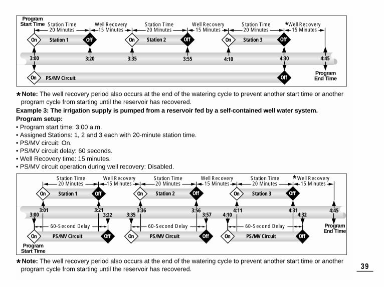
* Note: The well recovery period also occurs at the end of the watering cycle to prevent another start time or anotherprogram cycle from starting until the reservoir has recovered.
Example 3: The irrigation supply is pumped from a reservoir fed by a self-contained well water system.Program setup:• Program start time: 3:00 a.m.• Assigned Stations: 1, 2 and 3 each with 20-minute station time.• PS/MV circuit: On.• PS/MV circuit delay: 60 seconds.• Well Recovery time: 15 minutes.• PS/MV circuit operation during well recovery: Disabled.
* Note: The well recovery period also occurs at the end of the watering cycle to prevent another start time or anotherprogram cycle from starting until the reservoir has recovered. 39
Station Time20 Minutes
60-Second Delay 60-Second Delay
Off
Station Time20 Minutes
Station Time20 Minutes
3:573:35 3:56
Well Recovery15 Minutes
Well Recovery15 Minutes
Well Recovery15 Minutes
60-Second Delay
4:45
*
On
3:36
PS/MV CircuitOn Off
OffStation 3
4:32 4:10 4:31
On
4:11
OffStation 1 Station 2
3:223:00 3:21
On
3:01
PS/MV CircuitOn Off
Program End Time
Program Start Time
PS/MV CircuitOn Off
Station Time20 Minutes
Off
Station Time20 Minutes
Station Time20 Minutes
3:55
Well Recovery15 Minutes
Well Recovery15 Minutes
Well Recovery15 Minutes
4:45
*
On
3:35
OffStation 3
4:30
On
4:10
OffStation 1 Station 2
3:20
On
3:00
PS/MV CircuitOn OffProgram End Time
Program Start Time

40
If you are having a problem with the controller, check the following symptoms, possible causes and remedies. If the problem can not be resolved or you would like assistance with any Toro irrigation product, call 1-800-664-4740or 1-951-688-9221 (outside U.S.) Monday through Friday, 7:30 a.m – 4:00 p.m. (Pacific Standard Time).
Troubleshooting
Possible Cause
Main power is disconnected.
Watering programs have overlap-ping start times (stacked).
Faulty wire connection at stationmodule.
Shorted valve wire connection orfaulty solenoid. Electronic Fuse hasdisabled station operation.
No station time entered.Valve problem generally caused by a bonnet leak or corroded solenoid.
Season Adjust setting greater than100%.
Watering programs have overlap-ping start times (stacked).
Remedy
Check the transformer connections(indoor model) or circuit breaker atservice panel (outdoor model).
Reduce station times. Change/removeprogram start times. (See p. 27).
Remove wire from station module.Strip back enough insulation to see1/8" of bare wire when fully inserted.
Repair wire connections. Inspect solenoid and repair or replace as necessary.
Enter a station time (See p. 28).Inspect valve bonnet seal and/or solenoid. Replace as needed.
Review Season Adjust factor andreset to 100%. (See p. 34)
Reduce station times. Change/removeprogram start times. (See p. 27).
Symptom
The display is blank and thecontroller does not operate.
Watering programs start atunscheduled times.
A station does not turn on.
A station does not turn off.
Program starts again after completion of a watering cycle.

Cabinet Dimensions:Indoor Model7.5" W x 8.5" H x 2" D (19cm W x 21.6cm H x 5cm D)Outdoor Model13.25" W x 9" H x 3.5" D (33.7cm W x 22.9cm H x 9cm D)
Power Specifications:Indoor Model - North AmericaPlug-in Transformer, Class 2, UL Listed, CSA-certified • Input: 120 VAC ± 10%, 50/60 Hz, 0.5A (60W)• Output: 24 VAC ± 10%, 50/60 Hz, 18 VA
Indoor Model - EuropePlug-in Transformer, TUV Approved• Input: 230 VAC ± 10%, 50/60 Hz, 0.1A (12W)• Output: 24 VAC ± 10%, 50/60 Hz, 18 VA
Indoor Model - AustraliaPlug-in Transformer, SAA Approved• Input: 240 VAC ± 10%, 50Hz, 0.1A (12W)• Output: 24 VAC ± 10%, 50 Hz, 18 VA
Outdoor Model - North AmericaBuilt-in Transformer, Class 2, UL Listed, CSA Certified(or equivalent)• Input: 120 VAC ± 10%, 50/60 Hz, 0.5A (60W)• Output: 24 VAC ± 10%, 50/60 Hz, 18 VA
Power Specifications (continued):Outdoor Model - EuropeBuilt-in Transformer, TUV Approved, SAA Approved• Input: 230 VAC ± 10%, 50/60 Hz, 0.1A• Output: 24 VAC ± 10%, 50/60 Hz, 20 VA
Outdoor Model - AustraliaBuilt-in Transformer, SAA Approved• Input: 240 VAC ± 10%, 50/60 Hz, 0.1A• Output: 24 VAC ± 10%, 50/60 Hz, 20 VA
Maximum Load Per Station:0.35A (8 VA) @ 24 VAC
Maximum Load For Pump/Master Valve:0.35A (8.4 VA) @ 24 VAC
Total Maximum Output: 0.7A (16.8 VA) @ 24 VAC(one station plus pump start/master valve circuit)
Temperature Limit Range:Operating: +14°F to +140°F (-10°C to +60°C)Storage: -22°F to +149°F (-30°C to +65°C)
Specifications
41

The Toro Promise – Limited Three- or Five-Year WarrantyThe Toro Company and its affiliate, Toro Warranty Company, pursuant to an agree-ment between them, jointly warrants, to the owner, each new piece of equipment(featured in the current catalog at date of installation) against defects in material andworkmanship for a period described below, provided they are used for irrigationpurposes under manufacturer's recommended specifications. Product failures dueto acts of God (i.e., lightning, flooding, etc.) are not covered by this warranty.
Neither Toro nor Toro Warranty Company is liable for failure of products notmanufactured by them even though such products may be sold or used in conjunc-tion with Toro products.
During such warranty period, we will repair or replace, at our option, any partfound to be defective. Your remedy is limited solely to the replacement or repair ofdefective parts.
Return the defective part to your local Toro distributor, who may be listed in yourtelephone directory Yellow Pages under "Irrigation Supplies" or "Sprinkler Systems,"or contact The Toro Warranty Company P.O. Box 489, Riverside, California, 92502.Phone (800) 664-4740 for the location of your nearest Toro distributor or outsidethe U.S., call (951) 688-9221.
This warranty does not apply where equipment is used, or installation is per-formed, in any manner contrary to Toro’s specifications and instructions, nor whereequipment is altered or modified.
Neither Toro nor Toro Warranty Company is liable for indirect, incidental orconsequential damages in connection with the use of equipment, including butnot limited to: vegetation loss, the cost of substitute equipment or servicesrequired during periods of malfunction or resulting non-use, property damage orpersonal injury resulting from installer’s actions, whether negligent or otherwise.
Some states do not allow the exclusion or limitation of incidental or conse-quential damages, so the above limitation or exclusion may not apply to you.
All implied warranties, including those of merchantability and fitness foruse, are limited to the duration of this express warranty.
Some states do not allow limitations of how long an implied warranty lasts,so the above limitation may not apply to you.
This warranty gives you specific legal rights and you may have other rightswhich vary from state to state.
The TMC-212 high-surge controller is covered by this warranty for a period offive years from the date of installation.
The TMC-212 standard-surge controller is covered by this warranty for a periodof three years from the date of installation.
Domestic: This equipment has been tested an fond to comply with thelimits for a Class B digital device, pursuant to Part 15 of the FCC Rules.These limits are designed to provide reasonable protection against harm-ful interference in a residential installation. This equipment generates,uses and can radiate radio frequency energy and, if not installed andused in accordance with the instructions, may cause harmful interferenceto radio communications. However, there is no guarantee that interfer-ence will not occur in a particular installation. If this equipment doesharmful interference to radio or television reception, which can be deter-mined by turning the equipment off and on, the user is encouraged to tryto correct the interference by one or more of the following measures:
1. Reorient or relocate the receiving antenna.
2. Increase the separation between the equipment and receiver.
3. Connect the equipment into an outlet on a circuit different from that towhich the receiver is connected.
4. Consult the dealer or an experienced radio/TV technician for help.
The user may find the following booklet prepared by the Federal Com-munications Commission helpful:
“How To Identify and Resolve Radio-TV Interference Problems”. Thisbooklet is available from the U.S. Government Printing Office, Washing-ton, DC 20402. Stock No. 004-000-00345-4.
International: This is a CISPR 22 Class B product.
Electromagnetic CompatibilityWarranty
42 © 2004 The Toro Company, Irrigation Division •www.toro.com Form Number 373-0319 Rev. A