investigation of the behavior of beam-to-column …© de liège - università degli studi di napoli...
TRANSCRIPT

Université de Liège - Università degli Studi di Napoli Federico II
Investigation of the behavior ofbeam-to-column joints in seismic areas
Numerical investigation of the behavior of the panel zone
Master Thesis submitted by
JABBARI Ilyas
for the Master degree in
Ingénieur civil des constructions, à finalité approfondie
Members of the jury SupervisorsPr. R. LANDOLFO Pr. M. D’ANIELLOPr. J-P JASPART Eng. R. TARTAGLIAPr. J-F DEMONCEAU Co-SupervisorsEng. E. NUNEZ Eng. M. ZIMBRU
Academic Year 2014-2015.
Contents
1 Abstract 5
2 Introduction 6
3 State of the Art 93.1 Relevant Papers . . . . . . . . . . . . . . . . . . . . . . . . . . . . 13
4 Literature Approach 274.1 AISC . . . . . . . . . . . . . . . . . . . . . . . . . . . . . . . . . . . 27
4.1.1 Moment Resistance . . . . . . . . . . . . . . . . . . . . . . . 334.1.2 Stiffness . . . . . . . . . . . . . . . . . . . . . . . . . . . . . 34
4.2 Eurocode(Component Method) . . . . . . . . . . . . . . . . . . . . 354.2.1 Joint classification . . . . . . . . . . . . . . . . . . . . . . . 354.2.2 Resistance . . . . . . . . . . . . . . . . . . . . . . . . . . . . 384.2.3 Stiffness . . . . . . . . . . . . . . . . . . . . . . . . . . . . . 48
5 FE Validation 555.1 Model Assumption . . . . . . . . . . . . . . . . . . . . . . . . . . . 57
5.1.1 Model Geometry . . . . . . . . . . . . . . . . . . . . . . . . 575.1.2 Units . . . . . . . . . . . . . . . . . . . . . . . . . . . . . . 575.1.3 Element type . . . . . . . . . . . . . . . . . . . . . . . . . . 575.1.4 Interaction . . . . . . . . . . . . . . . . . . . . . . . . . . . 575.1.5 Material Property . . . . . . . . . . . . . . . . . . . . . . . 58
5.2 Validation of the FE assumptions . . . . . . . . . . . . . . . . . . . 635.2.1 Result Comparison . . . . . . . . . . . . . . . . . . . . . . . 64
6 Parametric Study 676.1 Geometry . . . . . . . . . . . . . . . . . . . . . . . . . . . . . . . . 676.2 Web Panel Stiffeners Investigation . . . . . . . . . . . . . . . . . . 69
6.2.1 Supplementary Web Plate Influence . . . . . . . . . . . . . 746.2.2 Continuity Plate Influence . . . . . . . . . . . . . . . . . . . 76
6.3 Results and Comparison with the Component Method . . . . . . . 776.4 Cost Evaluation . . . . . . . . . . . . . . . . . . . . . . . . . . . . . 82
1
7 Conclusion 84
List of Figures 85
List of Tables 88
Bibliography 89
Nomenclature 91
2

ACKNOWLEDGEMENT
I would like to thank everybody that contributed to the realization of thisMaster Thesis.
It was a wonderful experience being able to realize my Thesis abroad, in theamazing city that Naples is, to learn a new language and to be surrounded by verycompetent and welcoming persons.
My sincere thanks go to Pr. Raffaele LANDOLFO and Pr. Mario D’ANIELLOfrom the Università degli studi di Napoli Federico II, and to Pr. J-P JASPARTand J-F DEMONCEAU from the Univeristé de Liege.
I thank my supervisor Roberto TARTAGLIA and my co-supervisor MarianaZIMBRU for the time and dedication they showed me.
I would like to thank my family: my parents and my brother for their supportduring my Erasmus and in life in general.
Last but not least, I would like to thank my girlfriend, Annalisa EICHHOLZER,for supporting me mentally during my thesis and making my adaption in Italy eas-ier.
3

STATEMENT
Steel portal frames used to be designed considering the joints either ideallypinned or fully rigid. Although this simplified the analysis and structural designprocess, a real and detailed understanding of the behavior of the joint was notpossible. Indeed, joints in reality have all a finite stiffness and are thus semi-rigid.The joint behavior should be considered.
The codifications in Europe evolved over time and in 2005, the version pub-lished of the Eurocode 3 was exclusively dedicated to all types of joints, where theresponse of the joints was considered dependent of the geometrical and mechanicalproperties of their components by means of the component method.
However, in the Eurocode, the component method is limited to monotonic load-ing. Further studies in order to allow for a codified practice of beam-to-columnjoints submitted to seismic loading is needed.
In this paper, the results of a numerical parametric study focusing on the be-havior of the column web panel zone of beam-to-column moment resisting framesin seismic area are presented. The finite element models were realized using theprogram Abaqus. Equal strength-double sided joints (IPE600-HEB650) are in-vestigated under monotonic loading. The influence of the addition of continuityplates and supplementary web plates of different thicknesses is examined.Then acomparison with the results obtained from the component method is realized.
Members of the Jury:
J-F DEMONCEAU R.LANDOLFO
J-P JASPART E.NUNEZ
4
Chapter 1
Abstract
In this study, the results of a numerical parametric study on the behavior of thecolumn web panel zone of beam-to-column moment resisting frames in seismic areaare presented. Partial and Equal strength double sided joints are numerically mod-eled.First, a non-exhaustive list of papers relevant to this study is presented. Then abrief review of the methods presented in the Eurocode (components method) and inthe AISC (yield line theory) in order to obtain the moment-rotation curves of thejoints presented here (known geometry and materials properties) is done.Then, the description and validation of the Finite Element models used to modelour joints (IPE360-HEB340, IPE450-HEB500, IPE600-HEB650) are made.Finally, the results of the parametric study under monotonic loading of our jointsare presented in order to show the influence of the different column web reinforce-ment methods used (continuity plates, supplementary web plate).
Dans cette étude, les résultats d’une étude numérique sur le comportement dela zone de l’âme d’une colonne dans un assemblage poutre-colonne d’un portiquerésistant au moment, situé dans une zone sismique, sont présentés.Des assemblages à résistance égale et à résistance partielle sont réalisés numérique-ment. Tout d’abord, une liste non exhaustive des publications pertinentes à cetteétude est présentée.Ensuite, une brève révision des méthodes présentées dans l’eurocode (Méthode descomposantes) et dans l’AISC (théorie de la ligne de plasticité) afin d’obtenir lacourbe moment-rotation d’un assemblage est effectuée.Puis, une description ainsi que la validation des modèles aux éléments finis util-isés pour modéliser nos assemblages (IPE360-HEB340, IPE450-HEB500, IPE600-HEB650) sont faites.Finalement, une étude paramétrique des assemblages soumis à une charge augmen-tant monotoniquement est réalisée afin de montrer l’effet des différentes techniquesde renforcement utilisées (Raidisseurs transversaux, doublure d’âme)
5
Chapter 2
Introduction
Traditionally, joints in steel portal frames were considered to be either ideallypinned (no moment is transferred) or fully rigid (moment is transferred, the rela-tive rotation between beam and column is null). Even if it permitted a simplifi-cation in the analysis and structural design processes, a detailed understanding ofthe real behavior of the joint was impossible. Indeed, joints in reality do not ex-hibit infinite or null stiffness but all have a finite stiffness and are thus semi-rigid.It was not until the 1930’s that studies on the effect of moment-rotation relation-ship of semi-rigid joints on steel structures began.In the last decades, many analytical methods of semi-rigid joints were developed,from the slope-deflection equation and moment distribution methods, to matrixstiffness methods and, at present, to iterative methods coupling the global andjoint structural analysis.In 1984, the Comission of the European Community published the first version ofthe Eurocode 3. In this version, the joints were classified as rigid and semirigid forelastic linear analysis and with full or partial strength for elastic-plastic analysis.However, their use or the way to model them was not considered.The Eurocode evolved and in May 2005, a new version of the Eurocode 3 waspublished. It was exclusively dedicated to all types of joints, where the response ofthe joints was considered dependent of the geometrical and mechanical propertiesof their components (using the component method).
All researchers agree that the joint rotational behavior should be considered.In order to do so, several models were developed to obtain the moment-rotationcurve of the joint: analytical, empirical, experimental, informational, mechanicaland numerical models.
According to the traditional design practices, the best way to dissipate theseismic input energy was by concentrating the dissipative zones at the beam endsand avoiding the plastic engagement of the elements constituting the connection[Mazzolani and Piluso, 1996; Bruneau et al., 1998, Faella et al.,2000].
6
However after the Kobe (1994) and Northridge (1995) seismic events, many con-cerns have raised up in the engineering community. These events revealed unde-sirable brittle failures in beam-to-column connections, which causes the seismicperformance of such connections (welded connection) to be reconsidered.The failure of the joint welds and premature fracture, for the Northridge case, canbe attributed to the excessive distortion in the panel zone.Brittle fractures in welded joints can generally be attributed to : Workmanship(welding defects), detailing(stress concentration at the root or toe of welds), ma-terials (low toughness weld metal), and high seismic input (high strain rates).In fact, the displacement/deformation are the number one cause of damage inbuildings during the seismic event.
Extended bolted end-plates connections are quite popular in moment resitingjoints because of their simplicity and economy in their design, fabrication anderection. Besides these advantages, bolted beam-to-column connections, in com-parison to welded connections, offer an enhanced ductility (because less rigid), anda better welding quality (because performed in the shop under controlled condi-tions). This type of connection will be affected by many parameters such as boltdiameter, number of bolt rows and columns, bolt spacing, bolt grade, end-platedimensions, stiffener, column and beam sizes, bolt pretension force, yield strengthof steel, slip coefficient of contact surfaces, etc.
During earthquakes, a large energy dissipation of the structure is required. Astructure resisting the seismic forces only in the elastic range would be very ex-pensive. It is thus interesting to be able to use the inelastic range of a structure,provided that a correct understanding and control of the performance in the in-elastic range is achieved.
There are different possibilities in order to dissipate the seismic input energywhen designing a moment resisting frame in a seismic region:- Designing the joint as full-strength joint, forcing the location of the plastic hingesat the beam ends.- Designing the joint as partial-strength joint, forcing the dissipation of the seismicinput energy in the connection.
Full strength are more expensive than partial strength. But since in partialstrength connections, the joint becomes the main dissipative component, a accu-rate behavior assessment has to be done. It has been recognized that semi-rigidpartial strength connections have dissipation and ductility capacity compatiblewith the seismic demand (provided a good design with an appropriate choice ofthe joint component where the dissipation has to occur).
It is well known that the component method (codified in Eurocode),which will
7
be explained in Chapter 4, allows computation of the moment-rotation response ofa joint, provided that all the joint component are identified. It is very important toknow that the Eurocode gives information for evaluating the monotonic behaviorof beam-to-column connections, but it does not give any indication for the cyclicbehavior of the joint. But the Eurocode 8 [3] opened the door to the idea of dis-sipating the seismic input energy in the connecting elements of beam-to-columnjoints.The Eurocode 8 [3] does not allow for the yielding of the column web panel zone(the part of the column between the column flanges and the extension of the beamflanges, that transfers moment through a shear panel [5]), aiming for a ’strongpanel zone-weak beam’ design. However, a better understanding of the behaviorof the column web panel would allow for the use the panel zone as a dissipativecomponent (as already allowed in the American prevision)
Therefore, the use of the panel zone as a dissipative component and the ways toenhance its performance have motivated several studies on the column web panelzone, including this one.
8
Chapter 3
State of the Art
It is important to point out that The Eurocode 8 [3] does not allow for the yieldingof the column web panel zone, aiming for a ’strong panel zone-weak beam’ design.However the Eurocode achieves the total opposite by overestimating the strengthof the panel zone, which as explained in [34], is due to the value considered forthe shear area (too large), and to the contribution of the element surrounding thepanel zone (column flanges, continuity plates if stiffened), which should not betaken into account since their contribution is fully reached only for large deforma-tion of the panel zone, thus when it is already in the plastic range (contradictory).However allowing yielding of the column web panel zone (as in the AISC) canbe beneficial, when the joint is submitted to seismic loading, in terms of energydissipation. In this chapter, is presented an in-exhaustive list of papers publishedmostly about bolted end-plate steel connection, which is the type of connectioninvestigated in this project. But also papers about other types of connections thatmight be relevant to the investigation of the column web panel, which is the maingoal of this paper.
As explained in [18], the panel zone element is mainly a rotational spring ele-ment which transfers moment between the columns and beam framing in a joint.The moment transferred being related to the relative rotation between the columnsand beams connected.
The behavior of the panel zone is extremely important under lateral loadingsuch as seismic conditions. Indeed, in this case, the panel zone is subjected to un-balanced moment which cause shear deformation. Thus, the behavior of the panelzone has a very significant role in the overall stiffness and capacity of the frame.Indeed, depending on the type of connection, the column web panel (CWP) cansupply the most important part or even the entire rotation capacity of the joint(Dubina and al, 2001)
Several previous research have showed that the panel zone has a ductile and
9
stable behavior, allowing concentration of inelasticity to be used in order to de-crease the demand on the beams. However, large deformation of the panel zonecan cause additional second-order effects and high concentration of stresses in thewelds. Therefore, as mentioned in [8], the amplitude of the plastic deformation inthe panel needs to be correctly evaluated and controlled.
As explained in [11] and shown by Schneider and Amidi (1998), the CWP dis-tortions can influence by about 10% of the total lateral drift and the base shearstrength by 30% in the case of regular moment resisting frame MRF. They alsoreported that a CWP submitted to shear develops a maximum strength signifi-cantly greater than the yielding strength (due to its strain-hardening effect), theCWP shows very good ductile behavior in the inelastic range for monotonic andcyclic loading (for the cyclic loading, the hysteretic loop is stable for large defor-mations), and that the maximum shear of a CWP is not easily attained due to thelarge interstory drift required to attain the full resistance.
As explained in [9], panel zone can be either classified in terms of strengthas strong, intermediate or weak. Strong panels being able to resist the bendingcapacity of the adjacent beam. Weak panel zones allowing large energy dissipationwithin the panels. However due to the large deformations needed and the problemsfollowing from these deformations, weak panel are rarely used. On the contrary,intermediate strength panel zone allow the inelastic demands to be shared betweenthe panel zone and the beam, which requires the panel to yield at similar load levelsas those causing the flexural plastic hinges in the beams.
Several tests have been performed to investigate the load-deformation behaviorof the joint panel, and the following observations were made in [18] from these tests:
- A maximum strength significantly greater than the strength at first yield isoften developed in joint panel zones. This is due to strain hardening and to thecontribution of the column flanges in resisting panel zone shear forces. In order todevelop the maximum panel zone strength, large inelastic panel zone deformationsare required.
- In both case of elastic and inelastic ranges of behavior, the panel zone defor-mations can have a significant contribution to the overall deformation of a SMRF(Steel moment resisting frame).
- The strength and stiffness of the panel zone can be increased by addingsupplementary web plate, which effectiveness is affected by the method used toconnect them to the column.
- The panel zone can have very ductile behavior in the inelastic range, for bothmonotonic and cyclic loading. Also, the hysteresis loops are often stable, even at
10
large inelastic deformations.
- Large inelastic deformations are more likely to cause brittle fracture of beamflange to column flange weld. This effect is attributed to the large localized defor-mations or ’kinks’ in the column flanges at the boundaries of the panel zone.
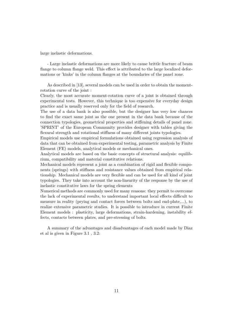
As described in [13], several models can be used in order to obtain the moment-rotation curve of the joint :Clearly, the most accurate moment-rotation curve of a joint is obtained throughexperimental tests. However, this technique is too expensive for everyday designpractice and is usually reserved only for the field of research.The use of a data bank is also possible, but the designer has very low chancesto find the exact same joint as the one present in the data bank because of theconnection typologies, geometrical properties and stiffening details of panel zone.’SPRINT’ of the European Community provides designer with tables giving theflexural strength and rotational stiffness of many different joints typologies.Empirical models use empirical formulations obtained using regression analysis ofdata that can be obtained from experimental testing, parametric analysis by FiniteElement (FE) models, analytical models or mechanical ones.Analytical models are based on the basic concepts of structural analysis: equilib-rium, compatibility and material constitutive relations.Mechanical models represent a joint as a combination of rigid and flexible compo-nents (springs) with stiffness and resistance values obtained from empirical rela-tionship. Mechanical models are very flexible and can be used for all kind of jointtypologies. They take into account the non-linearity of the response by the use ofinelastic constitutive laws for the spring elementsNumerical methods are commonly used for many reasons: they permit to overcomethe lack of experimental results, to understand important local effects difficult tomeasure in reality (prying and contact forces between bolts and end-plate,...), torealize extensive parametric studies. It is possible to introduce in current FiniteElement models : plasticity, large deformations, strain-hardening, instability ef-fects, contacts between plates, and pre-stressing of bolts.
A summary of the advantages and disadvantages of each model made by Diazet al is given in Figure 3.1 , 3.2:
11
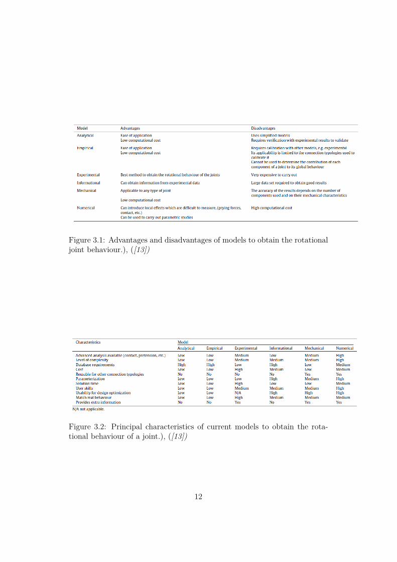
Figure 3.1: Advantages and disadvantages of models to obtain the rotationaljoint behaviour.), ([13])
Figure 3.2: Principal characteristics of current models to obtain the rota-tional behaviour of a joint.), ([13])
12
3.1 Relevant PapersMany papers relevant to this study have been published before (Numerical, ana-lytical and experimental studies):
• In [7], Bursi and Jaspart presented part of a study devoted to the analysis ofbolted steel connections by means of finite elements and concluded that thecomparison between computed and measured values in each phase of theirwork highlighted the effectiveness and degree of accuracy of the proposedFE models.
• As concluded in [8], Castro and Al. presented a new approach for repre-senting the panel zone component in steel and composite moment resistingframes. The contribution of the column flanges to the extra resistance ofthe panel zone is accounted for. The procedure considers both shear andbending deformations, and addresses the elastic and inelastic stages. Thecomparison with available experimental results coupled with detailed nu-merical simulations showed good accuracy and reliability of the method.As explained in [8]. Usually, The panel is typically assumed to have rigidboundaries and to behave under pure shear stress state. This simplificationallows the conversion of the bending moment into horizontal forces, whichleads to a set of simple analytical expressions for the idealized springs. Itis also considered that beyond yielding of the panel, the shear stiffness pro-vided by the column web effectively drops to that corresponding to strain-hardening of the material.Additional study to account for the contribution of the Continuity plates tothe extra resistance of the panel zone would also be of good concern.
• In [9], Castro et al reviewed the various approaches for panel zone designavailable in Europe and in the U.S.. They did a numerical study in orderto investigate the influence of a number of parameters on the inelastic re-sponse of the structure. The limitations of the Eurocode concerning the webpanel zone were pointed out. Indeed, an overestimation of the panel zonecapacity in Eurocode 3 leads to quite weak panel zones (Despite the statedobjective of achieving relatively strong panel zone). Castro et al showedthat the Eurocode overestimates the contribution of the column flanges tothe shear capacity by not taking into account the initial stress state in thecolumn flanges before these components are mobilized in the response, andconsidering the full plastic capacity of the column flanges. A comparisonwith the AISC showed that the contribution of the column flanges accord-ing to Eurocode 3 is twice that of the U.S. provisions. However, also the UScodes, weak panel zone is achieved through design.They highlighted the benefits of adopting a balanced design for panel zones
13
(for relatively low gravity loads).Nevertheless, further numerical studies (supported by experimental tests)in order to have a more reliable codified design approach in terms of earth-quakes are encouraged.Also as pointed out in [9], they did not consider the uncertainty in terms ofmaterial strength, which thus needs further investigation.
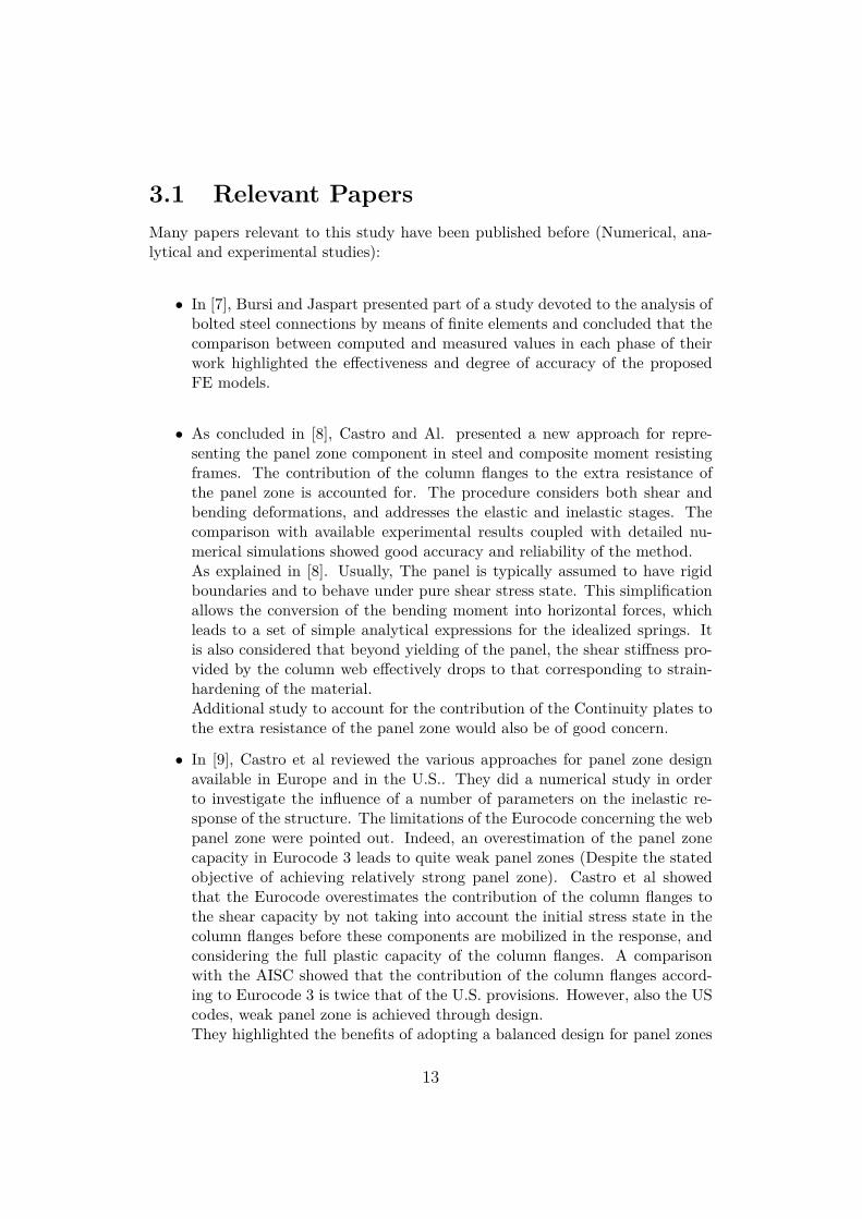
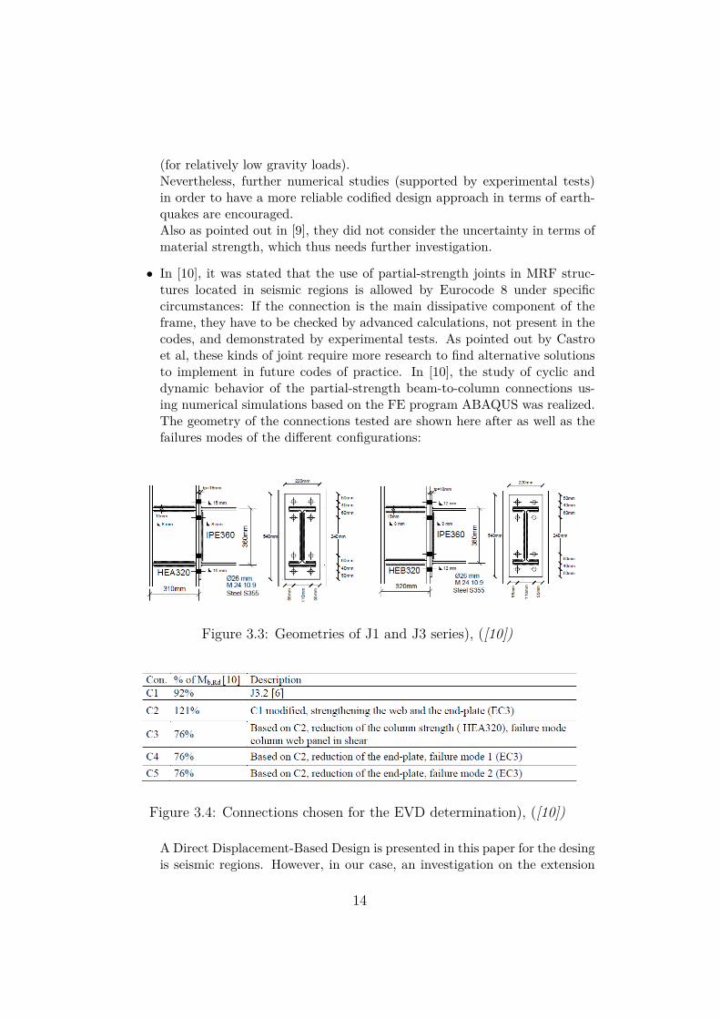
• In [10], it was stated that the use of partial-strength joints in MRF struc-tures located in seismic regions is allowed by Eurocode 8 under specificcircumstances: If the connection is the main dissipative component of theframe, they have to be checked by advanced calculations, not present in thecodes, and demonstrated by experimental tests. As pointed out by Castroet al, these kinds of joint require more research to find alternative solutionsto implement in future codes of practice. In [10], the study of cyclic anddynamic behavior of the partial-strength beam-to-column connections us-ing numerical simulations based on the FE program ABAQUS was realized.The geometry of the connections tested are shown here after as well as thefailures modes of the different configurations:
Figure 3.3: Geometries of J1 and J3 series), ([10])
Figure 3.4: Connections chosen for the EVD determination), ([10])
A Direct Displacement-Based Design is presented in this paper for the desingis seismic regions. However, in our case, an investigation on the extension
14
of the component method for seismic design would be more appropriate.
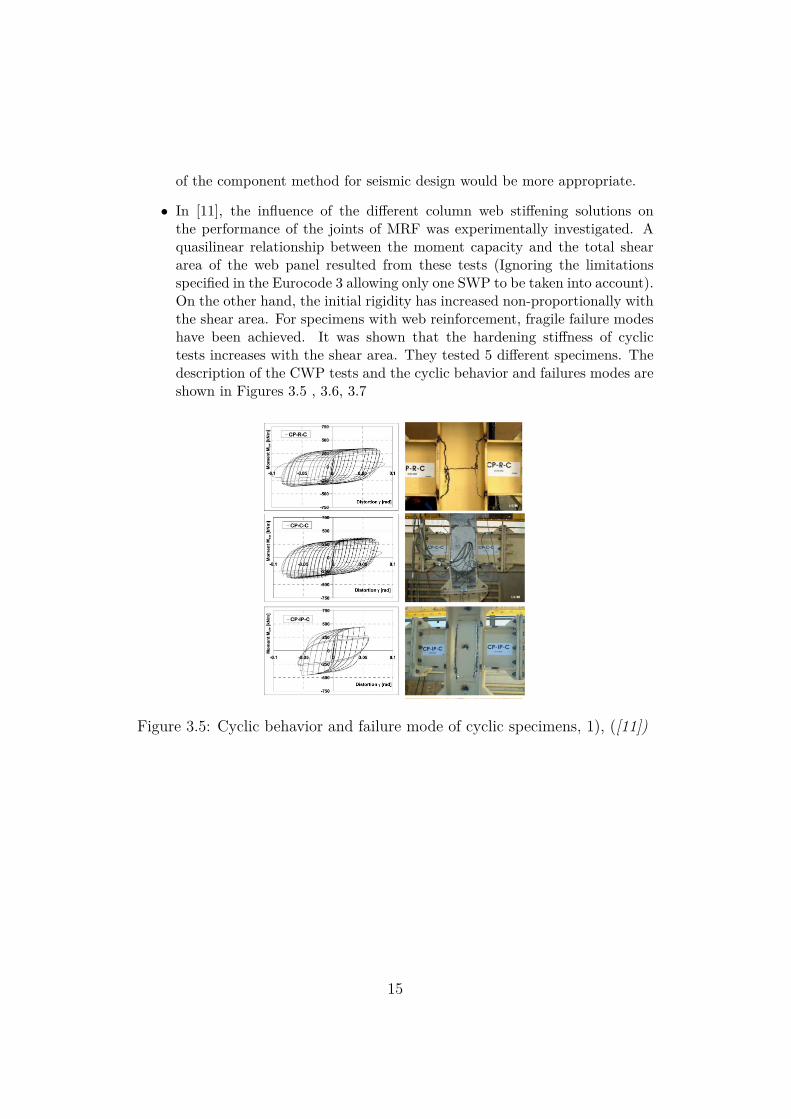
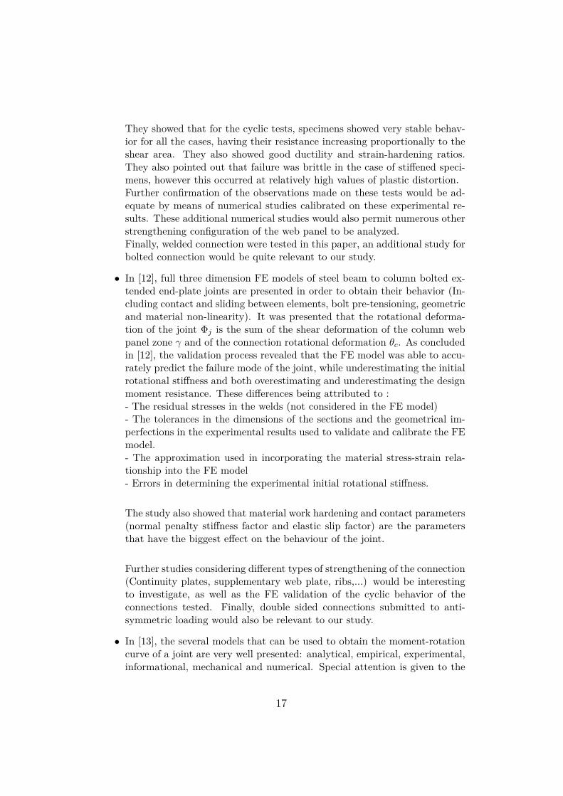
• In [11], the influence of the different column web stiffening solutions onthe performance of the joints of MRF was experimentally investigated. Aquasilinear relationship between the moment capacity and the total sheararea of the web panel resulted from these tests (Ignoring the limitationsspecified in the Eurocode 3 allowing only one SWP to be taken into account).On the other hand, the initial rigidity has increased non-proportionally withthe shear area. For specimens with web reinforcement, fragile failure modeshave been achieved. It was shown that the hardening stiffness of cyclictests increases with the shear area. They tested 5 different specimens. Thedescription of the CWP tests and the cyclic behavior and failures modes areshown in Figures 3.5 , 3.6, 3.7
Figure 3.5: Cyclic behavior and failure mode of cyclic specimens, 1), ([11])
15
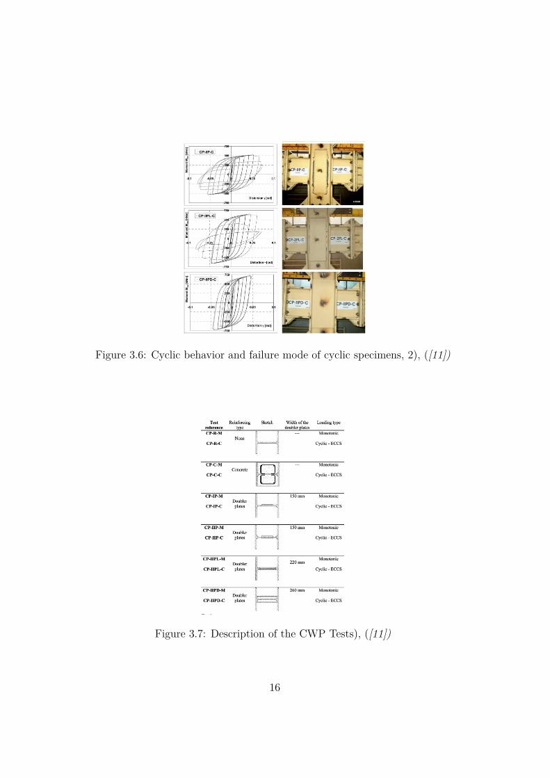
Figure 3.6: Cyclic behavior and failure mode of cyclic specimens, 2), ([11])
Figure 3.7: Description of the CWP Tests), ([11])
16
They showed that for the cyclic tests, specimens showed very stable behav-ior for all the cases, having their resistance increasing proportionally to theshear area. They also showed good ductility and strain-hardening ratios.They also pointed out that failure was brittle in the case of stiffened speci-mens, however this occurred at relatively high values of plastic distortion.Further confirmation of the observations made on these tests would be ad-equate by means of numerical studies calibrated on these experimental re-sults. These additional numerical studies would also permit numerous otherstrengthening configuration of the web panel to be analyzed.Finally, welded connection were tested in this paper, an additional study forbolted connection would be quite relevant to our study.
• In [12], full three dimension FE models of steel beam to column bolted ex-tended end-plate joints are presented in order to obtain their behavior (In-cluding contact and sliding between elements, bolt pre-tensioning, geometricand material non-linearity). It was presented that the rotational deforma-tion of the joint Φj is the sum of the shear deformation of the column webpanel zone γ and of the connection rotational deformation θc. As concludedin [12], the validation process revealed that the FE model was able to accu-rately predict the failure mode of the joint, while underestimating the initialrotational stiffness and both overestimating and underestimating the designmoment resistance. These differences being attributed to :- The residual stresses in the welds (not considered in the FE model)- The tolerances in the dimensions of the sections and the geometrical im-perfections in the experimental results used to validate and calibrate the FEmodel.- The approximation used in incorporating the material stress-strain rela-tionship into the FE model- Errors in determining the experimental initial rotational stiffness.
The study also showed that material work hardening and contact parameters(normal penalty stiffness factor and elastic slip factor) are the parametersthat have the biggest effect on the behaviour of the joint.
Further studies considering different types of strengthening of the connection(Continuity plates, supplementary web plate, ribs,...) would be interestingto investigate, as well as the FE validation of the cyclic behavior of theconnections tested. Finally, double sided connections submitted to anti-symmetric loading would also be relevant to our study.
• In [13], the several models that can be used to obtain the moment-rotationcurve of a joint are very well presented: analytical, empirical, experimental,informational, mechanical and numerical. Special attention is given to the
17
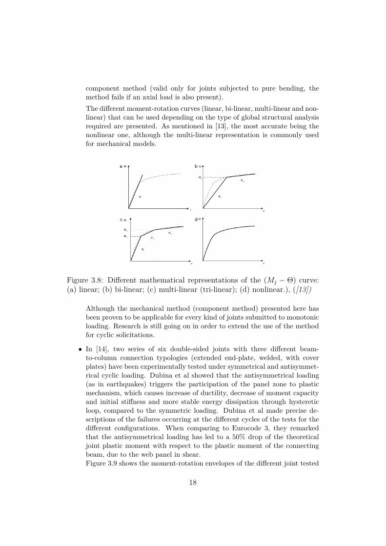
component method (valid only for joints subjected to pure bending, themethod fails if an axial load is also present).The different moment-rotation curves (linear, bi-linear, multi-linear and non-linear) that can be used depending on the type of global structural analysisrequired are presented. As mentioned in [13], the most accurate being thenonlinear one, although the multi-linear representation is commonly usedfor mechanical models.
Figure 3.8: Different mathematical representations of the (Mj − Θ) curve:(a) linear; (b) bi-linear; (c) multi-linear (tri-linear); (d) nonlinear.), ([13])
Although the mechanical method (component method) presented here hasbeen proven to be applicable for every kind of joints submitted to monotonicloading. Research is still going on in order to extend the use of the methodfor cyclic solicitations.
• In [14], two series of six double-sided joints with three different beam-to-column connection typologies (extended end-plate, welded, with coverplates) have been experimentally tested under symmetrical and antisymmet-rical cyclic loading. Dubina et al showed that the antisymmetrical loading(as in earthquakes) triggers the participation of the panel zone to plasticmechanism, which causes increase of ductility, decrease of moment capacityand initial stiffness and more stable energy dissipation through hystereticloop, compared to the symmetric loading. Dubina et al made precise de-scriptions of the failures occurring at the different cycles of the tests for thedifferent configurations. When comparing to Eurocode 3, they remarkedthat the antisymmetrical loading has led to a 50% drop of the theoreticaljoint plastic moment with respect to the plastic moment of the connectingbeam, due to the web panel in shear.Figure 3.9 shows the moment-rotation envelopes of the different joint tested
18
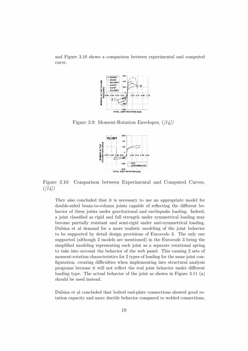
and Figure 3.10 shows a comparison between experimental and computedcurve.
Figure 3.9: Moment-Rotation Envelopes, ([14])
Figure 3.10: Comparison between Experimental and Computed Curves,([14])
They also concluded that it is necessary to use an appropriate model fordouble-sided beam-to-column joints capable of reflecting the different be-havior of these joints under gravitational and earthquake loading. Indeed,a joint classified as rigid and full strength under symmetrical loading maybecome partially resistant and semi-rigid under anti-symmetrical loading.Dubina et al demand for a more realistic modeling of the joint behaviorto be supported by detail design provisions of Eurocode 3. The only onesupported (although 2 models are mentioned) in the Eurocode 3 being thesimplified modeling representing each joint as a separate rotational springto take into account the behavior of the web panel. This causing 2 sets ofmoment-rotation characteristics for 2 types of loading for the same joint con-figuration, creating difficulties when implementing into structural analysisprograms because it will not reflect the real joint behavior under differentloading type. The actual behavior of the joint as shown in Figure 3.11 (a)should be used instead.
Dubina et al concluded that bolted end-plate connections showed good ro-tation capacity and more ductile behavior compared to welded connections,
19
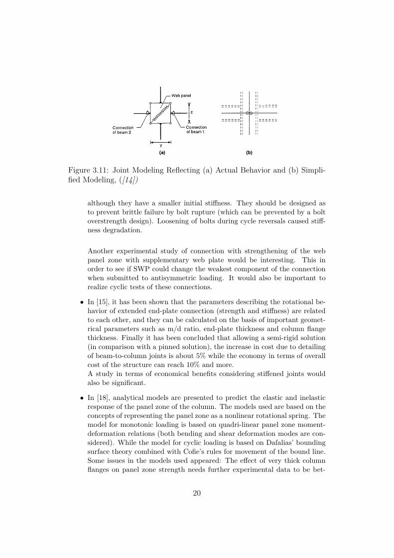
Figure 3.11: Joint Modeling Reflecting (a) Actual Behavior and (b) Simpli-fied Modeling, ([14])
although they have a smaller initial stiffness. They should be designed asto prevent brittle failure by bolt rupture (which can be prevented by a boltoverstrength design). Loosening of bolts during cycle reversals caused stiff-ness degradation.
Another experimental study of connection with strengthening of the webpanel zone with supplementary web plate would be interesting. This inorder to see if SWP could change the weakest component of the connectionwhen submitted to antisymmetric loading. It would also be important torealize cyclic tests of these connections.
• In [15], it has been shown that the parameters describing the rotational be-havior of extended end-plate connection (strength and stiffness) are relatedto each other, and they can be calculated on the basis of important geomet-rical parameters such as m/d ratio, end-plate thickness and column flangethickness. Finally it has been concluded that allowing a semi-rigid solution(in comparison with a pinned solution), the increase in cost due to detailingof beam-to-column joints is about 5% while the economy in terms of overallcost of the structure can reach 10% and more.A study in terms of economical benefits considering stiffened joints wouldalso be significant.
• In [18], analytical models are presented to predict the elastic and inelasticresponse of the panel zone of the column. The models used are based on theconcepts of representing the panel zone as a nonlinear rotational spring. Themodel for monotonic loading is based on quadri-linear panel zone moment-deformation relations (both bending and shear deformation modes are con-sidered). While the model for cyclic loading is based on Dafalias’ boundingsurface theory combined with Cofie’s rules for movement of the bound line.Some issues in the models used appeared: The effect of very thick columnflanges on panel zone strength needs further experimental data to be bet-
20
ter accounted for; The effectiveness of supplementary web plate also needsadditional studies in order to better quantify the contribution of the SWPto the panel zone strength and stiffness for different attachment details (one side, both sides, welding details, etc). Finally, the models presented in[18], though they account for material yielding and strain hardening, needfurther studies in order to be able to predict strength degradation due toinstability (shear buckling) or fracture of the column or beam flanges at thecorner of the panel zone.
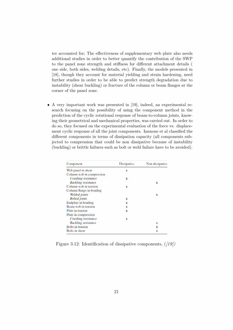
• A very important work was presented in [19], indeed, an experimental re-search focusing on the possibility of using the component method in theprediction of the cyclic rotational response of beam-to-column joints, know-ing their geometrical and mechanical properties, was carried out. In order todo so, they focused on the experimental evaluation of the force vs. displace-ment cyclic response of all the joint components. Iannone et al classified thedifferent components in terms of dissipation capacity (all components sub-jected to compression that could be non dissipative because of instability(buckling) or brittle failures such as bolt or weld failure have to be avoided).
Figure 3.12: Identification of dissipative components, ([19])
21
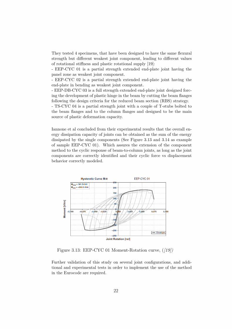
They tested 4 specimens, that have been designed to have the same flexuralstrength but different weakest joint component, leading to different valuesof rotational stiffness and plastic rotational supply [19]:- EEP-CYC 01 is a partial strength extended end-plate joint having thepanel zone as weakest joint component.- EEP-CYC 02 is a partial strength extended end-plate joint having theend-plate in bending as weakest joint component.- EEP-DB-CYC 03 is a full strength extended end-plate joint designed forc-ing the development of plastic hinge in the beam by cutting the beam flangesfollowing the design criteria for the reduced beam section (RBS) strategy.- TS-CYC 04 is a partial strength joint with a couple of T-stubs bolted tothe beam flanges and to the column flanges and designed to be the mainsource of plastic deformation capacity.
Iannone et al concluded from their experimental results that the overall en-ergy dissipation capacity of joints can be obtained as the sum of the energydissipated by the single components (See Figure 3.13 and 3.14 as exampleof sample EEP-CYC 01). Which assures the extension of the componentmethod to the cyclic response of beam-to-column joints, as long as the jointcomponents are correctly identified and their cyclic force vs displacementbehavior correctly modeled.
Figure 3.13: EEP-CYC 01 Moment-Rotation curve, ([19])
Further validation of this study on several joint configurations, and addi-tional and experimental tests in order to implement the use of the methodin the Eurocode are required.
22
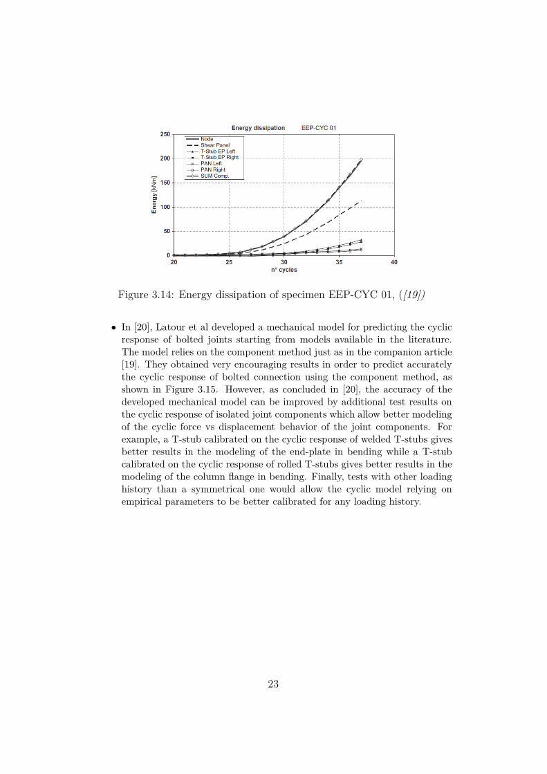
Figure 3.14: Energy dissipation of specimen EEP-CYC 01, ([19])
• In [20], Latour et al developed a mechanical model for predicting the cyclicresponse of bolted joints starting from models available in the literature.The model relies on the component method just as in the companion article[19]. They obtained very encouraging results in order to predict accuratelythe cyclic response of bolted connection using the component method, asshown in Figure 3.15. However, as concluded in [20], the accuracy of thedeveloped mechanical model can be improved by additional test results onthe cyclic response of isolated joint components which allow better modelingof the cyclic force vs displacement behavior of the joint components. Forexample, a T-stub calibrated on the cyclic response of welded T-stubs givesbetter results in the modeling of the end-plate in bending while a T-stubcalibrated on the cyclic response of rolled T-stubs gives better results in themodeling of the column flange in bending. Finally, tests with other loadinghistory than a symmetrical one would allow the cyclic model relying onempirical parameters to be better calibrated for any loading history.
23
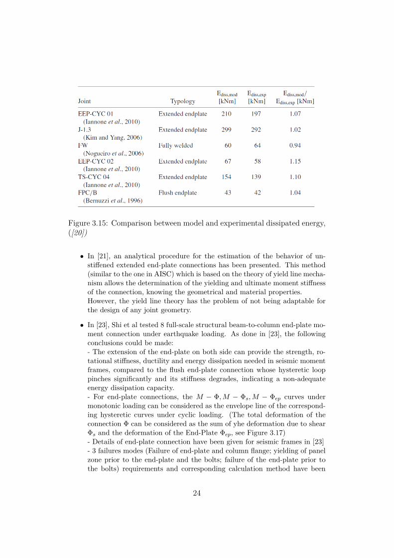
Figure 3.15: Comparison between model and experimental dissipated energy,([20])
• In [21], an analytical procedure for the estimation of the behavior of un-stiffened extended end-plate connections has been presented. This method(similar to the one in AISC) which is based on the theory of yield line mecha-nism allows the determination of the yielding and ultimate moment stiffnessof the connection, knowing the geometrical and material properties.However, the yield line theory has the problem of not being adaptable forthe design of any joint geometry.
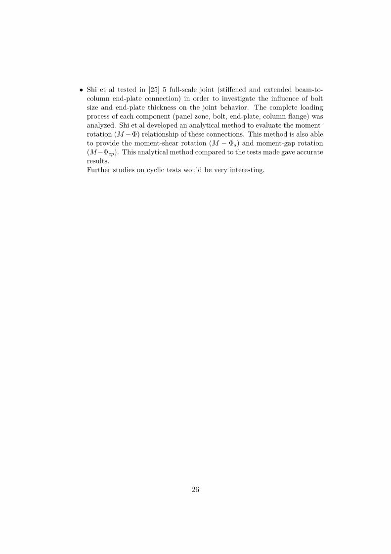
• In [23], Shi et al tested 8 full-scale structural beam-to-column end-plate mo-ment connection under earthquake loading. As done in [23], the followingconclusions could be made:- The extension of the end-plate on both side can provide the strength, ro-tational stiffness, ductility and energy dissipation needed in seismic momentframes, compared to the flush end-plate connection whose hysteretic looppinches significantly and its stiffness degrades, indicating a non-adequateenergy dissipation capacity.- For end-plate connections, the M − Φ,M − Φs,M − Φep curves undermonotonic loading can be considered as the envelope line of the correspond-ing hysteretic curves under cyclic loading. (The total deformation of theconnection Φ can be considered as the sum of yhe deformation due to shearΦs and the deformation of the End-Plate Φep, see Figure 3.17)- Details of end-plate connection have been given for seismic frames in [23]- 3 failures modes (Failure of end-plate and column flange; yielding of panelzone prior to the end-plate and the bolts; failure of the end-plate prior tothe bolts) requirements and corresponding calculation method have been
24
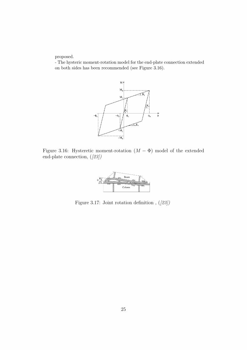
proposed.- The hysteric moment-rotation model for the end-plate connection extendedon both sides has been recommended (see Figure 3.16).
Figure 3.16: Hysteretic moment-rotation (M − Φ) model of the extendedend-plate connection, ([23])
Figure 3.17: Joint rotation definition , ([23])
25
• Shi et al tested in [25] 5 full-scale joint (stiffened and extended beam-to-column end-plate connection) in order to investigate the influence of boltsize and end-plate thickness on the joint behavior. The complete loadingprocess of each component (panel zone, bolt, end-plate, column flange) wasanalyzed. Shi et al developed an analytical method to evaluate the moment-rotation (M−Φ) relationship of these connections. This method is also ableto provide the moment-shear rotation (M − Φs) and moment-gap rotation(M−Φep). This analytical method compared to the tests made gave accurateresults.Further studies on cyclic tests would be very interesting.
26
Chapter 4
Literature Approach
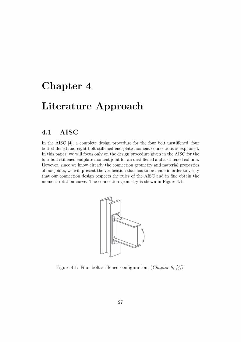
4.1 AISCIn the AISC [4], a complete design procedure for the four bolt unstiffened, fourbolt stiffened and eight bolt stiffened end-plate moment connections is explained.In this paper, we will focus only on the design procedure given in the AISC for thefour bolt stiffened endplate moment joint for an unstiffened and a stiffened column.However, since we know already the connection geometry and material propertiesof our joints, we will present the verification that has to be made in order to verifythat our connection design respects the rules of the AISC and in fine obtain themoment-rotation curve. The connection geometry is shown in Figure 4.1:
Figure 4.1: Four-bolt stiffened configuration, (Chapter 6, [4])
27
The design procedure for extended end-plate moment connections subject tocyclic loading is based on 4 points:
• The required connection design moment
• Connection bolt strength
• End plate strength
• Column flange bending strength
The procedure uses the yield-line theory for the determination of the end platestrength and the column flange flexural strength, and a simplified method to deter-mine the bolt forces. The following procedure is recommended for bolted end-platemoment connection subject to cyclic/seismic forces.
AISC Procedure
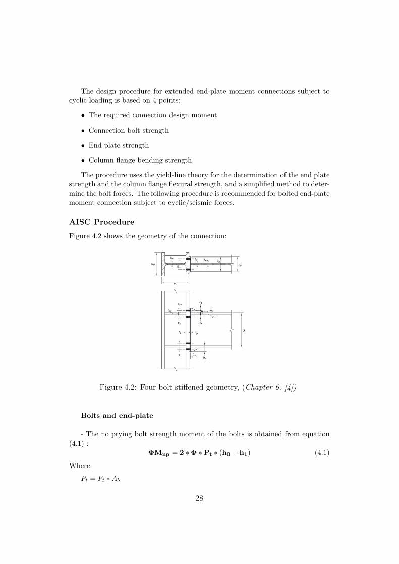
Figure 4.2 shows the geometry of the connection:
Figure 4.2: Four-bolt stiffened geometry, (Chapter 6, [4])
Bolts and end-plate
- The no prying bolt strength moment of the bolts is obtained from equation(4.1) :
ΦMnp = 2 ∗Φ ∗Pt ∗ (h0 + h1) (4.1)
Where
Pt = Ft ∗Ab
28
Ab = Π∗d2b
4
Φ = 0.75
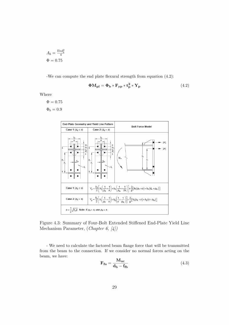
-We can compute the end plate flexural strength from equation (4.2):
ΦMpl = Φb ∗ Fyp ∗ t2p ∗Yp (4.2)
Where
Φ = 0.75
Φb = 0.9
Figure 4.3: Summary of Four-Bolt Extended Stiffened End-Plate Yield LineMechanism Parameter, (Chapter 6, [4])
- We need to calculate the factored beam flange force that will be transmittedfrom the beam to the connection. If we consider no normal forces acting on thebeam, we have:
Ffu = Mucdb − ffb
(4.3)
29
- Using a stiffened end-plate, the yielding and rupture resistance of the ex-tended portion of the end-plate do not have to be verified. However, we have toverify that the stiffener has the minimum thickness required:
ts,req = twb ∗FybFys
(4.4)
Also, in order to verify that no local buckling of the stiffener plate occurs, thefollowing criterion must be satisfied:
ts ≥ 1.79 ∗ hst ∗
√FysE
(4.5)
The stiffener-to-beam flange and stiffener-to-end plate welds must also be ver-ified. Indeed they have to be able to develop the stiffener plate in shear at thebeam flange and in tension at the end plate. For this purpose, either fillet orcomplete joint penetration (CPJ) welds are needed for the beam flange welds. Forthe stiffener-to-end plate weld, CPJ should be used for stiffener thickness greaterthan 3/8 in (9.525 mm) and fillet welds for thickness less or equal to 3/8 in (9.525Mm).
- The bolts have to be verified in both shear rupture and bolt bearing/tear outfailure of the end-plate and column flange.The bolt shear rupture strength of the joint is conservatively considered to beprovided by the bolts at the compression flange:
Rn = Φ ∗ nb ∗ Fv ∗Ab > Vu (4.6)
Where
Φ = 0.75
- Bolt bearing and tear out failure of the end plate and column flange is verifiedby:
Rn = Φ ∗ ni ∗Rn(InnerBolts) ∗ φ ∗ no(Outerbolts) > Vu (4.7)
Where
Φ = 0.75
Rn = 1.2 ∗ Lc ∗ t ∗ Fu < 2.4 ∗ dB ∗ t ∗ Fu , for each boltt = tc or tep
For our joint configurations, welds are considered to be full penetration.
30
Column side
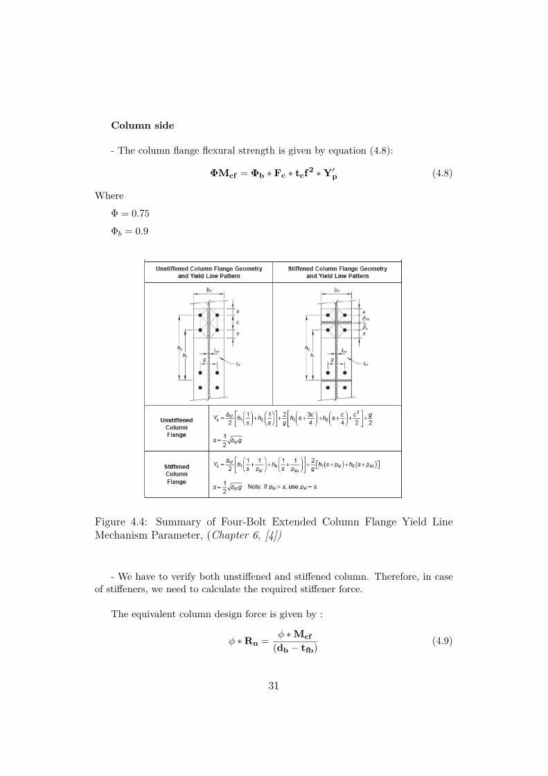
- The column flange flexural strength is given by equation (4.8):
ΦMcf = Φb ∗ Fc ∗ tcf2 ∗Y′p (4.8)
Where
Φ = 0.75
Φb = 0.9
Figure 4.4: Summary of Four-Bolt Extended Column Flange Yield LineMechanism Parameter, (Chapter 6, [4])
- We have to verify both unstiffened and stiffened column. Therefore, in caseof stiffeners, we need to calculate the required stiffener force.
The equivalent column design force is given by :
φ ∗Rn = φ ∗Mcf(db − tfb) (4.9)
31
- The unstiffened local column web yielding strength at the beam flange isgiven by equation (4.10):
φ ∗Rn = φ ∗Ct ∗ (6kc + N + 2tp) ∗ Fyc ∗ twc > Ffu (4.10)
Where
φ = 1.0
Ct = 1 because the distance from the column top to the top face of the beamflange is more than the depth of the column
- The column web buckling strength of the unstiffened column web at the beamcompression flange is given from equation (4.11):
φ ∗Rn = φ ∗ 24 ∗ t3wc ∗
√E ∗ Fyc
h > Ffu (4.11)
Where
Φ = 0.9
- The unstiffened column web crippling strength at the beam compressionflange is given by equation (4.12):
φ ∗Rn = Φ0.80t2wc[1 + 3( N
dc)(twc
tfc)1.5]
√EFyctfc
twc(4.12)
Where
Φ = 0.75
- If the column is stiffened with continuity plates, the required strength forthem is given by :
Fsu = Ffu −min(ΦRn) (4.13)
Where minΦRn is the minimum design strength value from the column flangebending, column web yielding, column web buckling and column web cripplingstrengths.
- Finally shear yielding and plate buckling strength of the column web panelzone must be checked according specification in [Seismic Provisions for Struc-tural Steel Buildings (AISC, 2002)]. The use of equation 4.14 and 4.15 appliedwhen frame stability, including plastic panel-zone deformation, is considered in
32
the analysis. These equations take into account the additional inelastic shearstrength available in a connection with adequate ductility. This inelastic shearstrength is often used for the design of frames in high seismic zones:
For Pr ≤ 0.75Pc
Rn = 0.60Fydctw(1 + 3bcft2cf
dbdctw) (4.14)
For Pr > 0.75Pc
Rn = 0.60Fydctw(1 + 3bcft2cf
dbdctw)(1.9− 1.2Pr
Pc) (4.15)
Where
Pc = Py [N] (LFRD)
Py = FyAc
4.1.1 Moment ResistanceAs mentioned earlier, as we already know the end-plate geometry, bolt diameter,beam and column geometry, and material properties, we can obtain the momentstrength (if the procedure criteria are respected) , ΦMn, according to the AISC,by :
• Calculating the end-plate bending strength, the column flange bending strength,and the no-prying bolt tension rupture strength, as explained before.
• Determining the behavior of the end-plate and column flange, being ’thick’or ’thin’, using the following equations:
For the end-plateIf Mpl > 1.1Mnp → ThickplateIf Mpl < 1.1Mnp → Thinplate
For the end-plateIf Mcf > 1.1Mnp → ThickflangeIf Mcf < 1.1Mnp → Thinflange
Thus, if both the end-plate and the column flange have thick plate behavior,then the connection design strength, is equal to the no prying bolt strength, ΦMnp.Otherwise, in case of thin plate behavior, the connection does not meet the re-quirements of the procedure presented. An additional limit state, bolt rupture
33

with prying, is induced by the thin plate behavior, whose computation is availablein [AISC/MBMA Design Guide 16 Flush and Extended Multiple-Row MomentEnd-Plate Connections (Murray and Shoemaker, 2002)].
4.1.2 StiffnessIn the AISC specifications, no procedure is described in order to calculate thestiffness of the joint. The connections are assumed either fully rigid or pinned.
34
4.2 Eurocode(Component Method)In the past, when designing steel portal frames, it was assumed that their beam-to-column joints were ideally pinned or fully rigid. With pinned joints, no moment istransmitted between the beam and the column, only axial and shear forces can betransferred. This means that they have no rotational stiffness. On the contrary,fully rigid joints have a rotational compatibility, which means that the relativeangle deformation between the beam and the column is null. They are able totransmit axial, shear and moment. Considering the connections pinned or fullyrigid decoupled the analysis of the joints from the analysis of the structure. It hadthe effect of simplifying the analysis and structural design process but preventeda detailed understanding of the behavior of the joints. Indeed, joints being inreality semi-rigid and having thus a finite stiffness. Therefore, the true behaviorof a joint had to be accounted in the global analysis of the structure. This wasachieved by using the moment-rotation curve, obtained from the determinationof the mechanical properties of the joint in terms of its rotational stiffness (Sj),moment resistance (Mj,Rd) and rotational capacity (Φj).The mechanical properties can be obtained from several models such as analyti-cal, empirical, experimental, informational, mechanical and numerical ones. Themost popular being the mechanical model, and among all of the ones available,the Component Method (a hybrid analytical-mechanical method), which will bedescribed here. The Component Method, being the method recommended in theEurocode 3, considers a joint as a set of individual basic components. Allowing thedetermination of the moment resistance and stiffness characteristics of the jointby calculating the ones of all the different components of it.As mentioned in [19], the Eurocode provides information for evaluating the mono-tonic behavior of beam-to-column connections, but does not give any indicationfor the modeling of the cyclic behavior of the joint components.
In this paper, we will focus on the bolted stiffened extended end plate connec-tions, and describe the Component Method procedure from [2] and described in[31] and [30] for this configuration.
4.2.1 Joint classificationStiffness Classification
According to its rotational stiffness, a joint can be classified as rigid, nominallypinned or semi-rigid, by comparing its initial rotational stiffness Sj,ini with theclassifications boundaries shown in Figure 4.5. The limits are defined as functionsof the stiffness of the beam and column.
35

Figure 4.5: Classification of joints by stiffness, (Chapter 5, [2])
Strength Classification
In terms of strength, comparing its design moment resistance Mj,Rd with the re-sistance of the members that it connects (members adjacent to the joint), a jointcan be classified as :
• Nominally pinned: The joint is capable of transmitting internal forces, with-out developing significant moments. A joint may be classified as pinned ifits design moment resistance Mj,Rd is not greater than a fourth of the de-sign moment resistance for a full-strength joint (provided sufficient rotationcapacity).
• Full strength joint: The joint must be able to develop a design moment re-sistant at least equal to the moment developed by its adjacent members, asdescribed in Figure 4.6:
• Partial joint: Any joint that does not fall into the 2 other categories.
The eurocode specifies that if the effects of the behavior of the joints on thedistribution of internal forces and moments within the structure are small, they
36
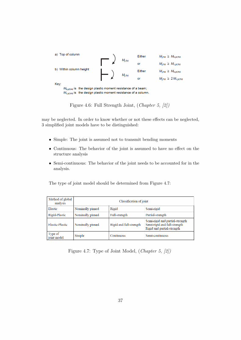
Figure 4.6: Full Strength Joint, (Chapter 5, [2])
may be neglected. In order to know whether or not these effects can be neglected,3 simplified joint models have to be distinguished:
• Simple: The joint is assumed not to transmit bending moments
• Continuous: The behavior of the joint is assumed to have no effect on thestructure analysis
• Semi-continuous: The behavior of the joint needs to be accounted for in theanalysis.
The type of joint model should be determined from Figure 4.7:
Figure 4.7: Type of Joint Model, (Chapter 5, [2])
37
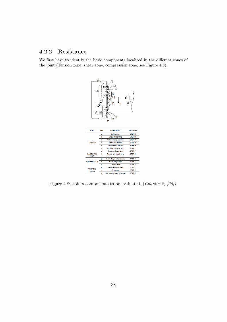
4.2.2 ResistanceWe first have to identify the basic components localized in the different zones ofthe joint (Tension zone, shear zone, compression zone; see Figure 4.8).
Figure 4.8: Joints components to be evaluated, (Chapter 2, [30])
38
Then, we have to characterize the behavior of each component in terms ofresistance-deformation. Finally, the components have to be assembled in a me-chanical model that consists of springs and rigid elements which will result in onesingle equivalent element characterized by the joint moment-rotation relation.
In order to calculate the moment resistance of the joint, we will have to calcu-late the resistance of every component.
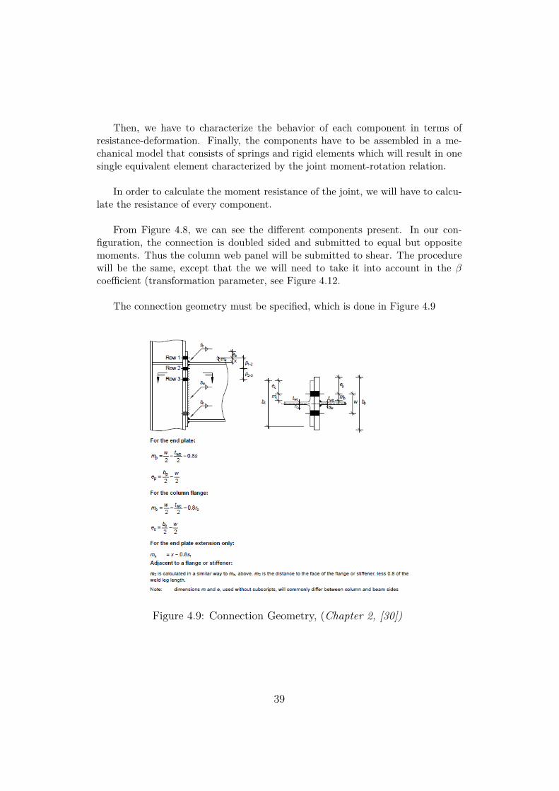
From Figure 4.8, we can see the different components present. In our con-figuration, the connection is doubled sided and submitted to equal but oppositemoments. Thus the column web panel will be submitted to shear. The procedurewill be the same, except that the we will need to take it into account in the βcoefficient (transformation parameter, see Figure 4.12.
The connection geometry must be specified, which is done in Figure 4.9
Figure 4.9: Connection Geometry, (Chapter 2, [30])
39
Resistance zone
The resistance of the connection can then be summarized as in [30], as followed:
- Resistance of the bolt rows in tension:
The effective design tension resistance is equal to the least of the followingresistance :
• End plate bending/bolt failure
• Column flange bending/bolt failure
• Column web in tension
• Beam web in tension
Ft,Rd(r) = min(Ft,fc,Rd,Ft,wc,Rd,Ft,ep,Rd,Ft,wb,Rd) (4.16)
For the IPE600-HEB650 connection, we also have to account for the fact thatthe resistance of a group of several rows may be less than the sum of the resis-tances of the individual rows. For the IPE360-HEB340 and IPE450-HEB500, weonly evaluate the resistance of individual rows because the bolts rows in tensionare separated by the beam flanges.
To determine the potential tension resistance of the end-plate in bending andthe column flange in bending, we need to calculate real yield line patterns con-verted into an equivalent T-stub. For that, we need to calculate the effective lengthof the equivalent T-stub according to table [T-Stub table].
40
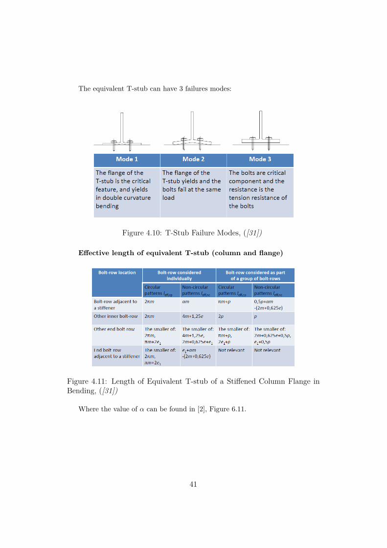
The equivalent T-stub can have 3 failures modes:
Figure 4.10: T-Stub Failure Modes, ([31])
Effective length of equivalent T-stub (column and flange)
Figure 4.11: Length of Equivalent T-stub of a Stiffened Column Flange inBending, ([31])
Where the value of α can be found in [2], Figure 6.11.
41

The resistance is thus equal to the minimum of the 3 modes:
• Mode 1 : FT,1,Rd = 4Mpl,1,Rdm
• Mode 2 : FT,2,Rd = 2Mpl,2,Rd+n∑
Ft,Rdm+n
• Mode 3 : FT,3,Rd =∑Ft,Rd
Where
Mpl,1,Rd = 0.25∑
leff,1t2ffy
γM0
Mpl,2,Rd = 0.25∑
leff,2t2ffy
γM0
n = emin ≤ 1.25m
Ft,Rd = 0.9fubAsγM2∑
Ft,Rd is the total of Ft,Rd for all bolts in the T-stub
γM2 = 1.25
γM0 = 1.00
- The design resistance of a column web without stiffener in transverse tensionis given by equation 4.2.2:
Ft,wc,Rd =ωbeff ,t,wctwcfy,wc
γM0(4.17)
42
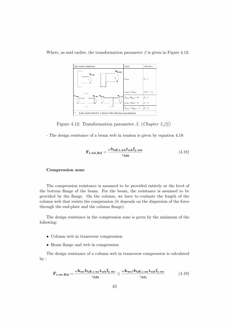
Where, as said earlier, the transformation parameter β is given in Figure 4.12:
Figure 4.12: Transformation parameter β, (Chapter 5,[2])
- The design resistance of a beam web in tension is given by equation 4.18:
Ft,wb,Rd =ωbeff ,t,wbtwbfy,wb
γM0(4.18)
Compression zone
The compression resistance is assumed to be provided entirely at the level ofthe bottom flange of the beam. For the beam, the resistance is assumed to beprovided by the flange. On the column, we have to evaluate the length of thecolumn web that resists the compression (it depends on the dispersion of the forcethrough the end-plate and the column flange).
The design resistance in the compression zone is given by the minimum of thefollowing:
• Column web in transverse compression
• Beam flange and web in compression
The design resistance of a column web in transverse compression is calculatedby :
Fc,wc,Rd =ωkwcbeff ,c,wctwbfy,wc
γM0≤ωkwcρbeff ,c,wctwbfy,wc
γM1(4.19)
43
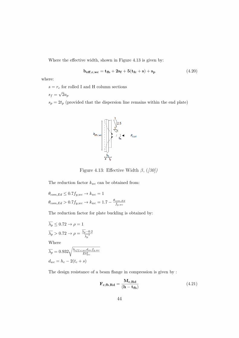
Where the effective width, shown in Figure 4.13 is given by:
beff ,c,wc = tfb + 2sf + 5(tfc + s) + sp (4.20)
where:
s = rc for rolled I and H column sections
sf =√
2apsp = 2tp (provided that the dispersion line remains within the end plate)
Figure 4.13: Effective Width β, ([30])
The reduction factor kwc can be obtained from:
θcom,Ed ≤ 0.7fy,wc → kwc = 1
θcom,Ed > 0.7fy,wc → kwc = 1.7− θcom,Edfy,wc
The reduction factor for plate buckling is obtained by:
λp ≤ 0.72→ ρ = 1
λp > 0.72→ ρ = λp−0.2λp
2
Where
λp = 0.932√
beff,c,wcdwcfy,wcEt2wc
dwc = hc − 2(tc + s)
The design resistance of a beam flange in compression is given by :
Fc,fb,Rd =Mc,Rd
(h− tfb) (4.21)
44
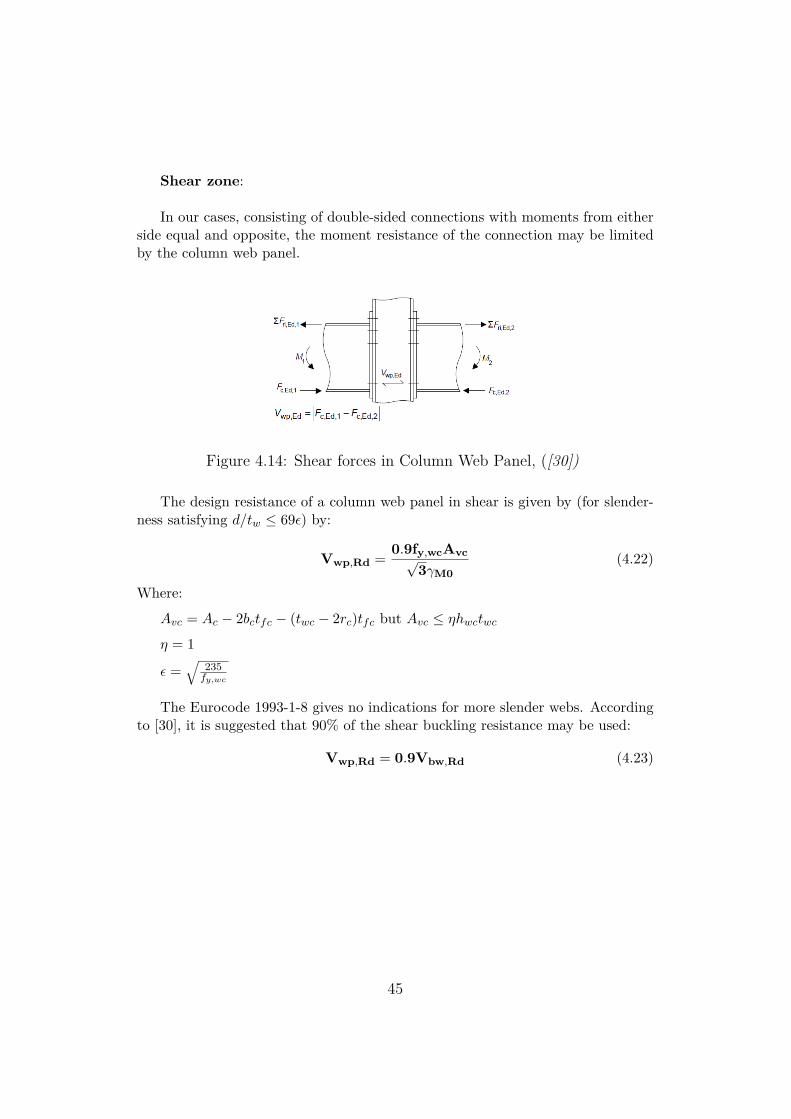
Shear zone:
In our cases, consisting of double-sided connections with moments from eitherside equal and opposite, the moment resistance of the connection may be limitedby the column web panel.
Figure 4.14: Shear forces in Column Web Panel, ([30])
The design resistance of a column web panel in shear is given by (for slender-ness satisfying d/tw ≤ 69ε) by:
Vwp,Rd = 0.9fy,wcAvc√3γM0
(4.22)
Where:
Avc = Ac − 2bctfc − (twc − 2rc)tfc but Avc ≤ ηhwctwcη = 1
ε =√
235fy,wc
The Eurocode 1993-1-8 gives no indications for more slender webs. Accordingto [30], it is suggested that 90% of the shear buckling resistance may be used:
Vwp,Rd = 0.9Vbw,Rd (4.23)
45
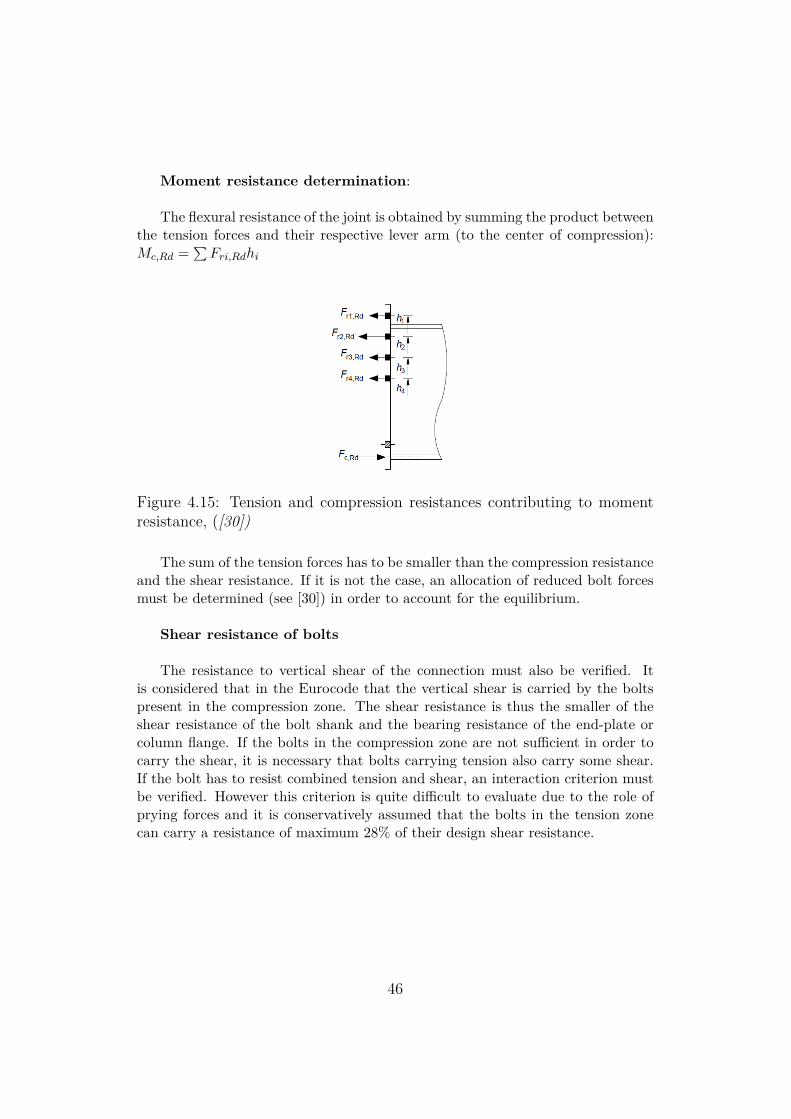
Moment resistance determination:
The flexural resistance of the joint is obtained by summing the product betweenthe tension forces and their respective lever arm (to the center of compression):Mc,Rd =
∑Fri,Rdhi
Figure 4.15: Tension and compression resistances contributing to momentresistance, ([30])
The sum of the tension forces has to be smaller than the compression resistanceand the shear resistance. If it is not the case, an allocation of reduced bolt forcesmust be determined (see [30]) in order to account for the equilibrium.
Shear resistance of bolts
The resistance to vertical shear of the connection must also be verified. Itis considered that in the Eurocode that the vertical shear is carried by the boltspresent in the compression zone. The shear resistance is thus the smaller of theshear resistance of the bolt shank and the bearing resistance of the end-plate orcolumn flange. If the bolts in the compression zone are not sufficient in order tocarry the shear, it is necessary that bolts carrying tension also carry some shear.If the bolt has to resist combined tension and shear, an interaction criterion mustbe verified. However this criterion is quite difficult to evaluate due to the role ofprying forces and it is conservatively assumed that the bolts in the tension zonecan carry a resistance of maximum 28% of their design shear resistance.
46
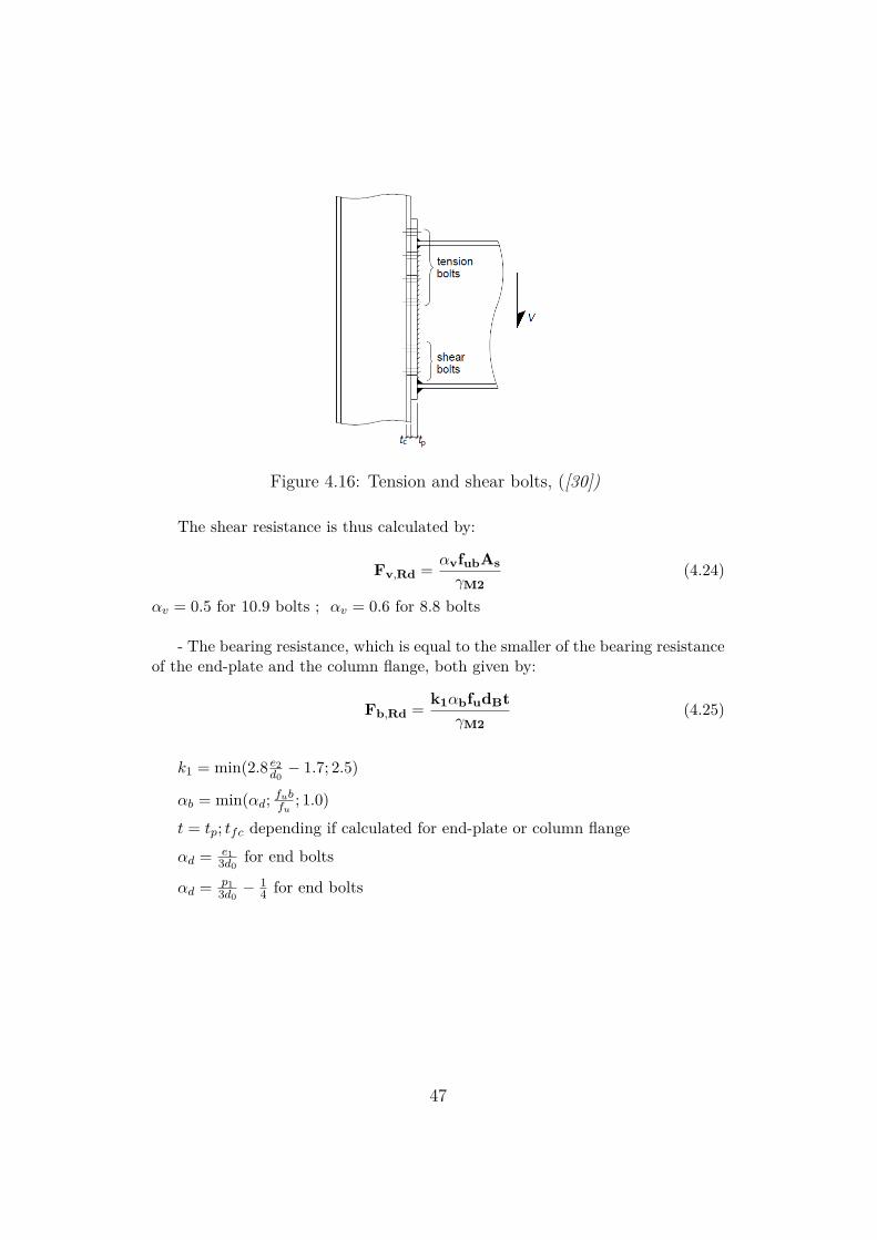
Figure 4.16: Tension and shear bolts, ([30])
The shear resistance is thus calculated by:
Fv,Rd = αvfubAsγM2
(4.24)
αv = 0.5 for 10.9 bolts ; αv = 0.6 for 8.8 bolts
- The bearing resistance, which is equal to the smaller of the bearing resistanceof the end-plate and the column flange, both given by:
Fb,Rd = k1αbfudBtγM2
(4.25)
k1 = min(2.8 e2d0− 1.7; 2.5)
αb = min(αd; fubfu ; 1.0)
t = tp; tfc depending if calculated for end-plate or column flange
αd = e13d0
for end bolts
αd = p13d0− 1
4 for end bolts
47
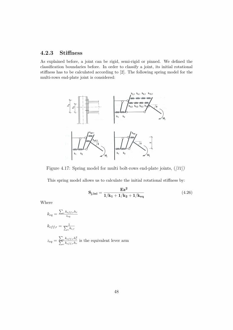
4.2.3 StiffnessAs explained before, a joint can be rigid, semi-rigid or pinned. We defined theclassification boundaries before. In order to classify a joint, its initial rotationalstiffness has to be calculated according to [2]. The following spring model for themulti-rows end-plate joint is considered:
Figure 4.17: Spring model for multi bolt-rows end-plate joints, ([31])
This spring model allows us to calculate the initial rotational stiffness by:
Sj,ini = Ez2
1/k1 + 1/k2 + 1/keq(4.26)
Where
keq =∑
rkeff,rhrzeq
keff,r = 1∑iki,r
zeq =∑
rkeff,rh
2r∑
rkeff,rhr
is the equivalent lever arm
48
Determination of the k coefficient of every component:
• Column web panel in shear:
Unstiffened : k1 = 0.38Avcβz
Stiffened : k1 =∞
Where
β = 2 in our case
• Column web in compression:
Unstiffened : k2 = 0.7beff,c,wctwcdc
Stiffened : k2 =∞
In case of bolted extended end-plate connection, the equivalent stiffnesscoefficient keq is based on the following ki coefficient:
• Column web in tensionUnstiffened : k3 = 0.7beff,t,wctwc
dc
Stiffened : k3 =∞
• Column flange in bending (for a single bolt-row in tension)
k4 = 0.9leff t3fcm3
Where
m is given in EN 1993-1-8 §6.2.6.4 Figure 6.8
• End-plate in bending (for a single bolt-row in tension)
k5 = 0.9leff ′ t3pm3
49
Where
m is given in EN 1993-1-8 §6.2.6.5 Figures 6.10
• Bolts in tension (for a single bolt-row in tension)
Unstiffened : k10 = 1.6AsLb
Stiffeners
There are many ways to increase the resistance and the rigidity of our connec-tion with the use of stiffeners.
Rib
First of all, we have to consider the rib stiffener.
Indeed,the rib stiffener is not yet covered by the Eurocode. We will thus usethe method proposed in [29]
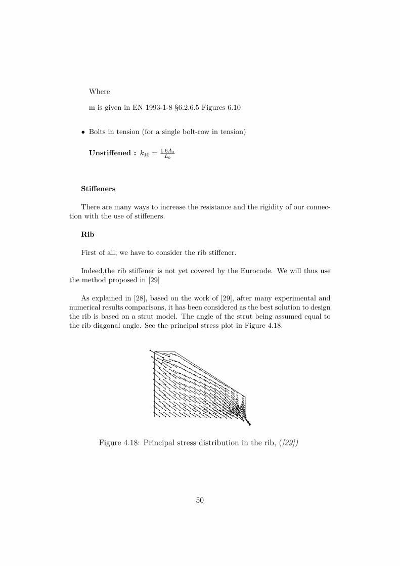
As explained in [28], based on the work of [29], after many experimental andnumerical results comparisons, it has been considered as the best solution to designthe rib is based on a strut model. The angle of the strut being assumed equal tothe rib diagonal angle. See the principal stress plot in Figure 4.18:
Figure 4.18: Principal stress distribution in the rib, ([29])
50

It was proven that the length of the rib does not have a large influence, andconsidering the width and the height as practical ranges, the minimum thicknesscan be calculated by considering the Von Mises yielding criterion and using theinteraction forces N and Q as followed:
t ≥√
Q2 + 3N2
b(ΦFyr) (4.27)
Where
Q =( (0.21a+0.15L′)adb
Ib)
(1/η) 0.6√a2+b2
√(a−c)2+(b−c)2
(ab−c2)t+ (0.18b+0.30db)adb
Ib
∗ Vpl
N ′ = ( ba) ∗Q
Where
a,b,c are the dimension of the rib as seen in Figure [29]
Φ = 0.90
η= 1.5 ; gives good results according to [29]
L′ is the span of the beam between the rib tips
51
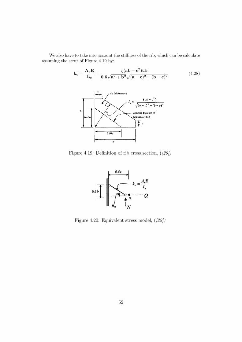
We also have to take into account the stiffness of the rib, which can be calculateassuming the strut of Figure 4.19 by:
ke = AeELe
= η(ab− c2)tE0.6√
a2 + b2√
(a − c)2 + (b− c)2(4.28)
Figure 4.19: Definition of rib cross section, ([29])
Figure 4.20: Equivalent stress model, ([29])
52
Continuity Plate
As seen earlier, the presence of continuity plate in the tension and the com-pression zone of the column web panel plays a big role in the stiffness value ofthese components.They also increase the bending resistance of the column flange and the tensionresistance of the column web in the tension zone. As well as increasing the com-pression resistance of the column web in the compression zone.In our case, the continuity plates are all full depth and are present symmetricallyon both side of the column web. The are aligned with the corresponding beamflange.According to [2], when continuity plate are used in both compression and tensionzone, the design plastic shear resistance of the column web panel Vwp,Rd may beincrease by Vwp,add,Rd, given by:
Vwp,add,Rd =4Mpl,fc,Rd
dsbut Vwp,add,Rd ≤
2Mpl,fc,Rd + 2Mpl,st,Rdds
(4.29)
Supplementary web plate (SWP):
Supplementary web plate will increase the shear resistance of the web panel,and also have an increasing effect on the tension and compression resistance of thecolumn web panel.Supplementary web plates are also used to increase the rotational stiffness of ajoint by increasing the stiffness of the column web in shear, compression or ten-sion.According to the Eurocode 1933-1-8, the supplementary web plate must fulfill thefollowing requirements:- The steel grade of the SWP should be the same as the one of the column.- The thickness of the SWP should be at least equal to the thickness of the columnweb.- The width of the SWP should go from the fillets of the column of one flange tothe ones of the other flange.- The width should not exceed 40εts.- The length of the SWP should at least go from the limit of the tension zone tothe limit of the compression zone on the column web.
53
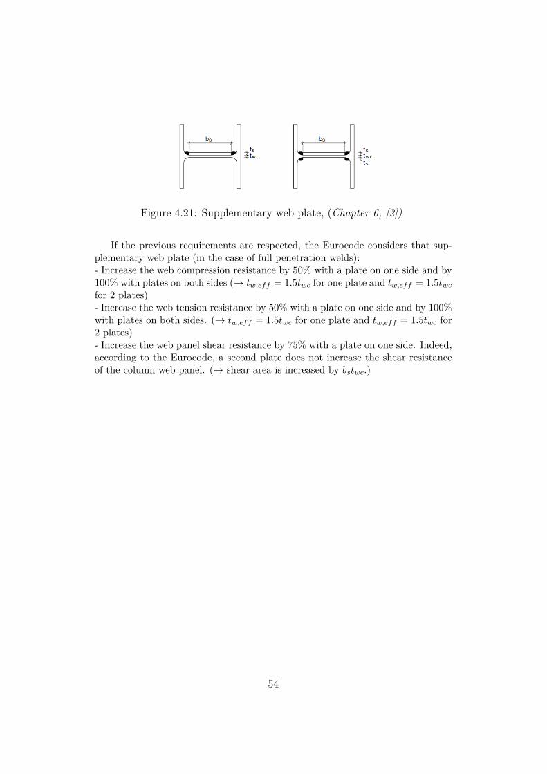
Figure 4.21: Supplementary web plate, (Chapter 6, [2])
If the previous requirements are respected, the Eurocode considers that sup-plementary web plate (in the case of full penetration welds):- Increase the web compression resistance by 50% with a plate on one side and by100% with plates on both sides (→ tw,eff = 1.5twc for one plate and tw,eff = 1.5twcfor 2 plates)- Increase the web tension resistance by 50% with a plate on one side and by 100%with plates on both sides. (→ tw,eff = 1.5twc for one plate and tw,eff = 1.5twc for2 plates)- Increase the web panel shear resistance by 75% with a plate on one side. Indeed,according to the Eurocode, a second plate does not increase the shear resistanceof the column web panel. (→ shear area is increased by bstwc.)
54
Chapter 5
FE Validation
Having a better understanding of the behavior of the joints is fundamental. There-fore, the most reliable sources of information are the experimental studies. How-ever, these studies are very expensive to carry. Indeed, in order to account for thelarge variability of the parameters, and their influence on the joint, a large numberof analysis have to been carried out.In order to do so, models using the finite elements method can be used. Thesemodels are inexpensive and robust, they allow the understanding of local effectswhich are difficult to measure accurately physically and they can be used to gen-erate extensive parametric studies.
Thus, the finite element models used in this project, were done using the soft-ware ABAQUS v.6-13. We will present here after the basic modeling assumptionsand the validation against experimental tests given by literature of the modelsused, as described in [33], on which our models are based on.
Two specimens out of the five stiffened extended end plate connections withdifferent end-plate thickness from [25] were selected to be numerically modeled inorder to validate the FE inputs used in the models.
Although, the models that we carried out (two sided beam connection) arenot exactly similar as the one presented here (one sided beam connection) , thevalidation presented here is relevant to our study.
55
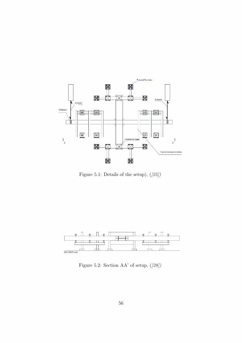
Figure 5.1: Details of the setup), ([25])
Figure 5.2: Section AA’ of setup, ([28])
56
5.1 Model Assumption5.1.1 Model GeometryThe beam and column length considered in the ABAQUS model are up to thepoint where the physical restraints are placed on the experimental specimens (asin Figure 5.1 and 5.2). The additional plate stiffener welded at the end of thebeam (used to increase the stiffness of the beam section where the load is appliedby means of the actuator) and at the end of the column (where the external hingesupports are located) are not represented in the FE model because they are con-sidered to have a negligible influence on the behavior of the joint.
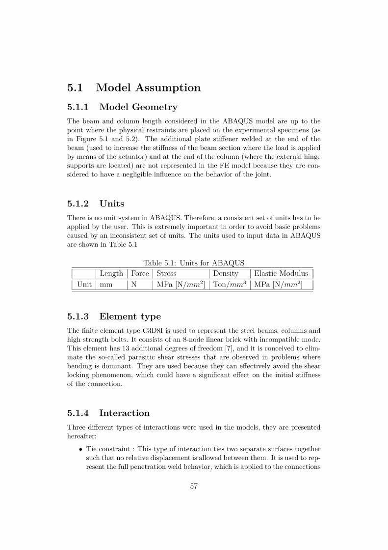
5.1.2 UnitsThere is no unit system in ABAQUS. Therefore, a consistent set of units has to beapplied by the user. This is extremely important in order to avoid basic problemscaused by an inconsistent set of units. The units used to input data in ABAQUSare shown in Table 5.1
Table 5.1: Units for ABAQUSLength Force Stress Density Elastic Modulus
Unit mm N MPa [N/mm2] Ton/mm3 MPa [N/mm2]
5.1.3 Element typeThe finite element type C3D8I is used to represent the steel beams, columns andhigh strength bolts. It consists of an 8-node linear brick with incompatible mode.This element has 13 additional degrees of freedom [7], and it is conceived to elim-inate the so-called parasitic shear stresses that are observed in problems wherebending is dominant. They are used because they can effectively avoid the shearlocking phenomenon, which could have a significant effect on the initial stiffnessof the connection.
5.1.4 InteractionThree different types of interactions were used in the models, they are presentedhereafter:
• Tie constraint : This type of interaction ties two separate surfaces togethersuch that no relative displacement is allowed between them. It is used to rep-resent the full penetration weld behavior, which is applied to the connections
57
between the beam and the end-plate, between the rib and the end-plate, be-tween the continuity plates and the column, and between the supplementaryweb plates and the column.
• Rigid-Body Constraint : This type of interaction is used to simulate theplanar behavior of a cross section and to integrate the mechanical responseof the whole section. Indeed, with this type of constraints, it is possible toapply the boundary conditions of the whole section in one point called areference point (which has to be defined). See Figure 5.7.
• Contact interaction: This type of interaction is used in order to represent theinteraction between surfaces that cannot penetrate each other and that arecharacterized by friction sliding (Surfaces of the bolt shank and hole, surfaceof the bolt head and the corresponding column flange surface, surface of thebolt nut and the corresponding end-plate surface, the surface in contactbetween the end-plate and the column). In order to do so, the tangentialbehavior is described by a "Coulomb friction" having a friction coefficientequal to 0.4. The normal behavior is described by "Hard contact".
5.1.5 Material PropertyIn order to have the most accurate results possible, the material stress-strain curvefrom the experimental tests used should be accounted for. However, since thereis a lack of data from the experimental tests, other materials tests reported inliterature were used for the stress-strain curve. As mentioned in [33],the plasticitymodel implemented in ABAQUS is based on Chaboche model and consists of anonlinear kinematic hardening component and an isotropic hardening component,as described by Wang et al. (2013).
Plates and members properties
For all elements (members and plates) of the connection, the same global materialproperty of Steel (S355) is used. The Young’s Modulus is assumed to be equal to210000 MPa and the Poisson’s ratio is assumed to be equal to 0.3..As shown in theplastic true stress - true strain is in Figure 5.3, the yield strength is 443.75 MPaand ultimate strength is 752.19 MPa.
Bolts Properties
Three different diameters of high strength bolts were used : M27, M30, M36.They are all of grade 10.9. The plastic true stress-true strain of the bolt materialis shown in figure 2.2:
58
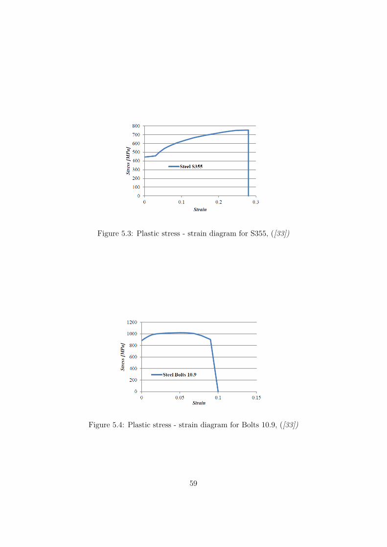
Figure 5.3: Plastic stress - strain diagram for S355, ([33])
Figure 5.4: Plastic stress - strain diagram for Bolts 10.9, ([33])
59
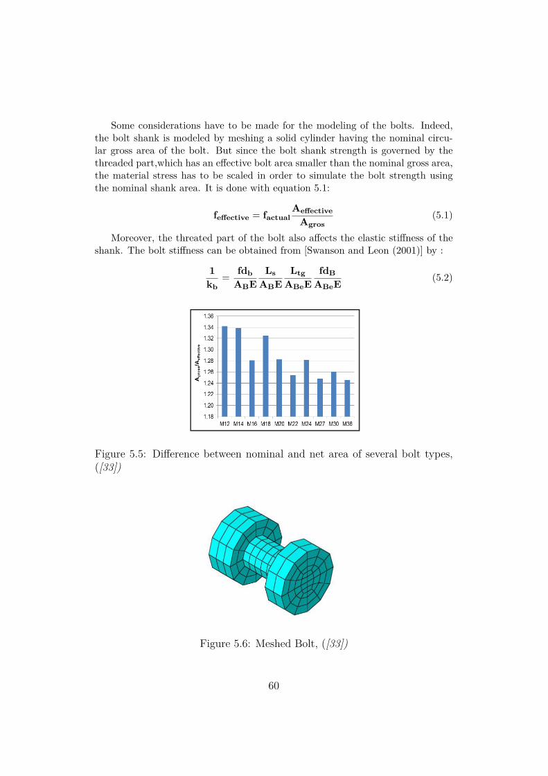
Some considerations have to be made for the modeling of the bolts. Indeed,the bolt shank is modeled by meshing a solid cylinder having the nominal circu-lar gross area of the bolt. But since the bolt shank strength is governed by thethreaded part,which has an effective bolt area smaller than the nominal gross area,the material stress has to be scaled in order to simulate the bolt strength usingthe nominal shank area. It is done with equation 5.1:
feffective = factualAeffective
Agros(5.1)
Moreover, the threated part of the bolt also affects the elastic stiffness of theshank. The bolt stiffness can be obtained from [Swanson and Leon (2001)] by :
1kb
= fdbABE
LsABE
LtgABeE
fdBABeE
(5.2)
Figure 5.5: Difference between nominal and net area of several bolt types,([33])
Figure 5.6: Meshed Bolt, ([33])
60
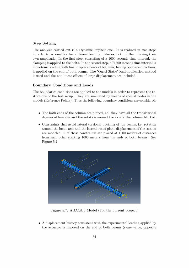
Step Setting
The analysis carried out is a Dynamic Implicit one. It is realized in two stepsin order to account for two different loading histories, both of them having theirown amplitude. In the first step, consisting of a 1000 seconds time interval, theclamping is applied to the bolts. In the second step, a 71500 seconds time interval, amonotonic loading with final displacements of 500 mm, having opposite directions,is applied on the end of both beams. The "Quasi-Static" load application methodis used and the non linear effects of large displacement are included.
Boundary Conditions and Loads
The boundaries conditions are applied to the models in order to represent the re-strictions of the test setup. They are simulated by means of special nodes in themodels (Reference Points). Thus the following boundary conditions are considered:
• The both ends of the column are pinned, i.e. they have all the translationaldegrees of freedom and the rotation around the axis of the column blocked.
• Constraints that avoid lateral torsional buckling of the beams, i.e. rotationaround the beam axis and the lateral out of plane displacement of the sectionare modeled. 2 of these constraints are placed at 1000 meters of distancesfrom each other starting 1000 meters from the ends of both beams. SeeFigure 5.7
Figure 5.7: ABAQUS Model (For the current project)
• A displacement history consistent with the experimental loading applied bythe actuator is imposed on the end of both beams (same value, opposite
61
direction). In the initial phase the displacement is restrained and in thesecond, it varies according to the imposed loading protocol. This allows tohave a smooth increase in the bending moment.
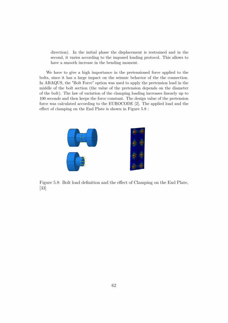
We have to give a high importance in the pretensioned force applied to thebolts, since it has a large impact on the seismic behavior of the the connection.In ABAQUS, the "Bolt Force" option was used to apply the pretension load in themiddle of the bolt section (the value of the pretension depends on the diameterof the bolt). The law of variation of the clamping loading increases linearly up to100 seconds and then keeps the force constant. The design value of the pretensionforce was calculated according to the EUROCODE [2]. The applied load and theeffect of clamping on the End Plate is shown in Figure 5.8 :
Figure 5.8: Bolt load definition and the effect of Clamping on the End Plate,[33]
62
Output from ABAQUS
Once the ABAQUS analysis is completed, several parameters have to be extractedfrom the output files such as the "z"displacement in the load direction of the ref-erence points at the extremity of the beams, the reaction force in the same points(which is used to calculate the moment applied to the connection through time,considering the lever arm of the point relative to the center of the connection),the "x" displacement of the continuity plates (above and below), the "x" and "z"displacements of the the tip of the rib on the beam flanges, the horizontal reactionsof the top and bottom of the column, the bolts reactions,... An important outputwas the PEEQ results. It represents the equivalent plastic strain, which is definedin [32].
Finally, the moment-rotation curve of the connection has to be found.
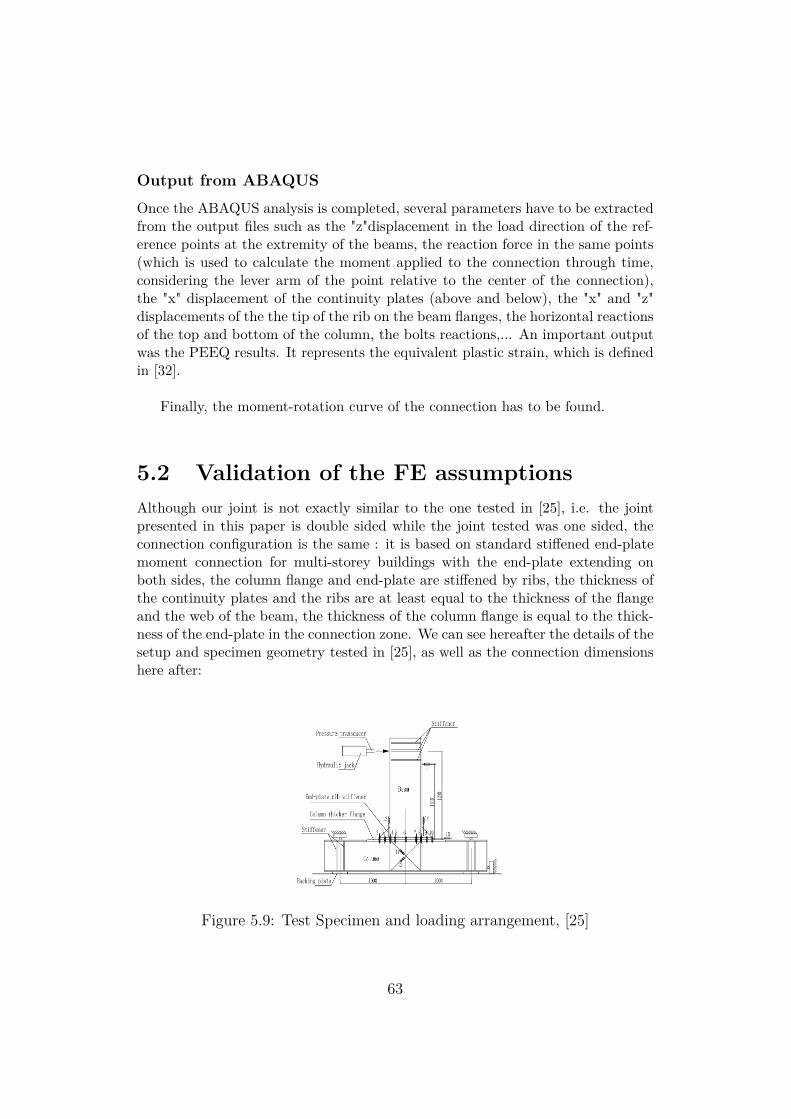
5.2 Validation of the FE assumptionsAlthough our joint is not exactly similar to the one tested in [25], i.e. the jointpresented in this paper is double sided while the joint tested was one sided, theconnection configuration is the same : it is based on standard stiffened end-platemoment connection for multi-storey buildings with the end-plate extending onboth sides, the column flange and end-plate are stiffened by ribs, the thickness ofthe continuity plates and the ribs are at least equal to the thickness of the flangeand the web of the beam, the thickness of the column flange is equal to the thick-ness of the end-plate in the connection zone. We can see hereafter the details of thesetup and specimen geometry tested in [25], as well as the connection dimensionshere after:
Figure 5.9: Test Specimen and loading arrangement, [25]
63
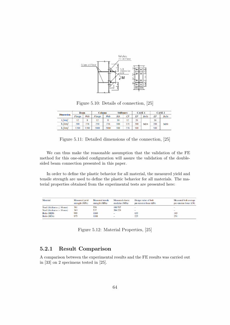
Figure 5.10: Details of connection, [25]
Figure 5.11: Detailed dimensions of the connection, [25]
We can thus make the reasonable assumption that the validation of the FEmethod for this one-sided configuration will assure the validation of the double-sided beam connection presented in this paper.
In order to define the plastic behavior for all material, the measured yield andtensile strength are used to define the plastic behavior for all materials. The ma-terial properties obtained from the experimental tests are presented here:
Figure 5.12: Material Properties, [25]
5.2.1 Result ComparisonA comparison between the experimental results and the FE results was carried outin [33] on 2 specimens tested in [25].
64
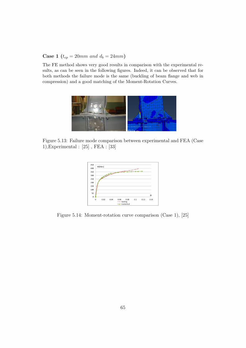
Case 1 (tep = 20mm and db = 24mm)The FE method shows very good results in comparison with the experimental re-sults, as can be seen in the following figures. Indeed, it can be observed that forboth methods the failure mode is the same (buckling of beam flange and web incompression) and a good matching of the Moment-Rotation Curves.
Figure 5.13: Failure mode comparison between experimental and FEA (Case1),Experimental : [25] , FEA : [33]
Figure 5.14: Moment-rotation curve comparison (Case 1), [25]
65
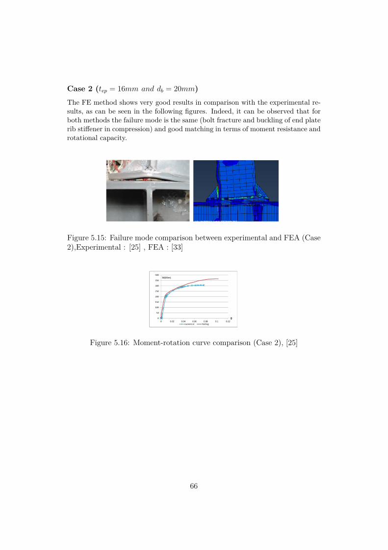
Case 2 (tep = 16mm and db = 20mm)The FE method shows very good results in comparison with the experimental re-sults, as can be seen in the following figures. Indeed, it can be observed that forboth methods the failure mode is the same (bolt fracture and buckling of end platerib stiffener in compression) and good matching in terms of moment resistance androtational capacity.
Figure 5.15: Failure mode comparison between experimental and FEA (Case2),Experimental : [25] , FEA : [33]
Figure 5.16: Moment-rotation curve comparison (Case 2), [25]
66
Chapter 6
Parametric Study
6.1 GeometryAs mentioned earlier, this paper will be focused on the investigation of the behav-ior of the panel zone of the column.A parametric study was conducted with the FE program ABAQUS.The joint configurations (all are double sided) that are investigated are the follow-ing:
• IPE360-HEB340 (equal and partial)
• IPE450-HEB500 (equal and partial)
• IPE600-HEB650 (equal and partial)
The design of these joints has been done according to the procedure followedin the EQUALJOINT project.
67
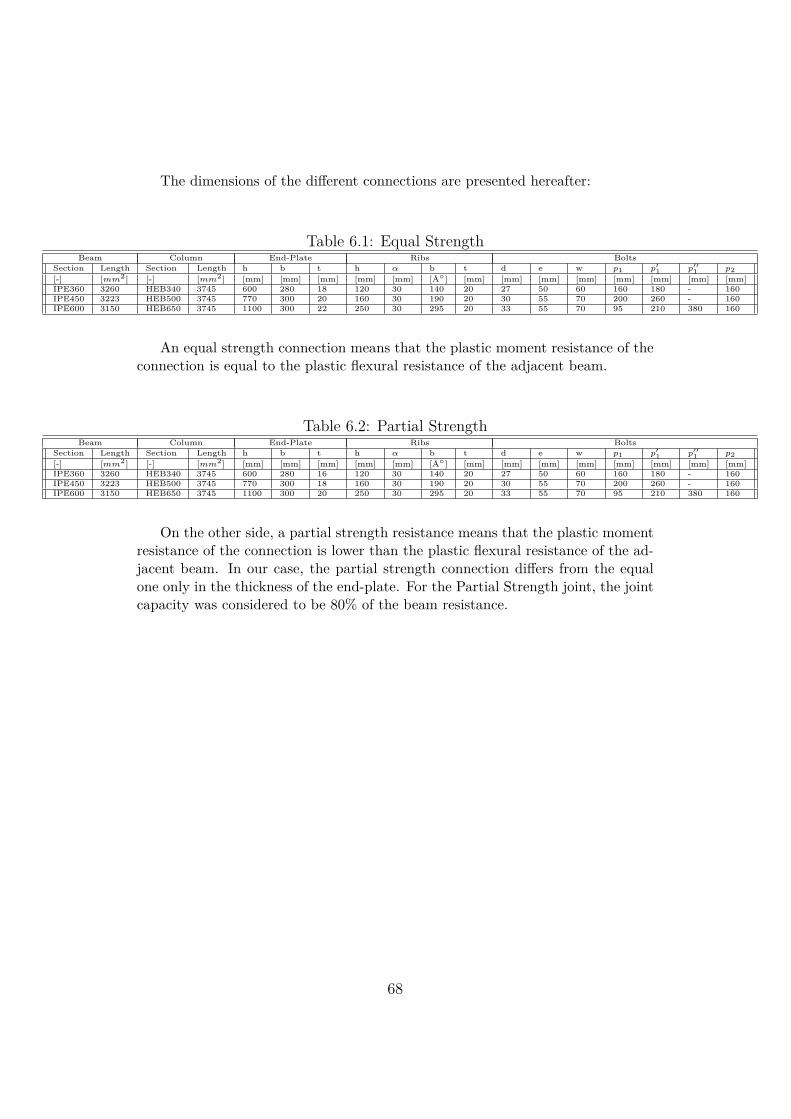
The dimensions of the different connections are presented hereafter:
Table 6.1: Equal StrengthBeam Column End-Plate Ribs Bolts
Section Length Section Length h b t h α b t d e w p1 p′1 p′′1 p2[-] [mm2] [-] [mm2] [mm] [mm] [mm] [mm] [mm] [Â◦] [mm] [mm] [mm] [mm] [mm] [mm] [mm] [mm]IPE360 3260 HEB340 3745 600 280 18 120 30 140 20 27 50 60 160 180 - 160IPE450 3223 HEB500 3745 770 300 20 160 30 190 20 30 55 70 200 260 - 160IPE600 3150 HEB650 3745 1100 300 22 250 30 295 20 33 55 70 95 210 380 160
An equal strength connection means that the plastic moment resistance of theconnection is equal to the plastic flexural resistance of the adjacent beam.
Table 6.2: Partial StrengthBeam Column End-Plate Ribs Bolts
Section Length Section Length h b t h α b t d e w p1 p′1 p′′1 p2[-] [mm2] [-] [mm2] [mm] [mm] [mm] [mm] [mm] [Â◦] [mm] [mm] [mm] [mm] [mm] [mm] [mm] [mm]IPE360 3260 HEB340 3745 600 280 16 120 30 140 20 27 50 60 160 180 - 160IPE450 3223 HEB500 3745 770 300 18 160 30 190 20 30 55 70 200 260 - 160IPE600 3150 HEB650 3745 1100 300 20 250 30 295 20 33 55 70 95 210 380 160
On the other side, a partial strength resistance means that the plastic momentresistance of the connection is lower than the plastic flexural resistance of the ad-jacent beam. In our case, the partial strength connection differs from the equalone only in the thickness of the end-plate. For the Partial Strength joint, the jointcapacity was considered to be 80% of the beam resistance.
68
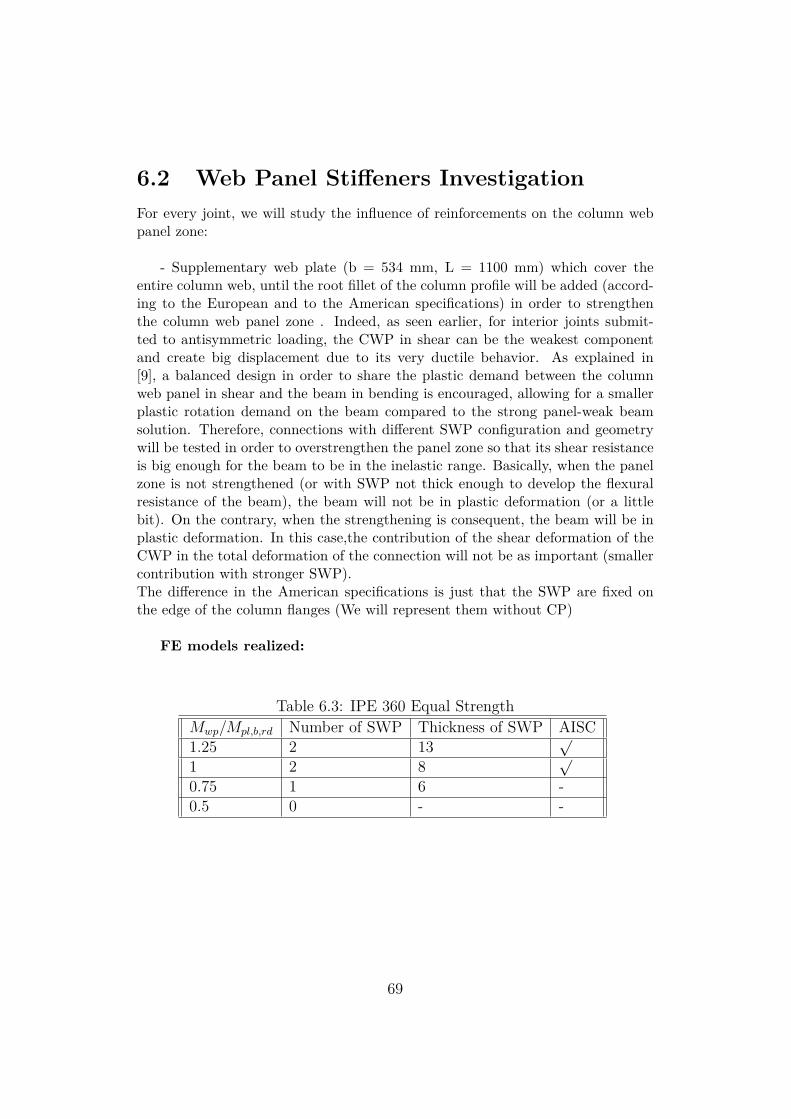
6.2 Web Panel Stiffeners InvestigationFor every joint, we will study the influence of reinforcements on the column webpanel zone:
- Supplementary web plate (b = 534 mm, L = 1100 mm) which cover theentire column web, until the root fillet of the column profile will be added (accord-ing to the European and to the American specifications) in order to strengthenthe column web panel zone . Indeed, as seen earlier, for interior joints submit-ted to antisymmetric loading, the CWP in shear can be the weakest componentand create big displacement due to its very ductile behavior. As explained in[9], a balanced design in order to share the plastic demand between the columnweb panel in shear and the beam in bending is encouraged, allowing for a smallerplastic rotation demand on the beam compared to the strong panel-weak beamsolution. Therefore, connections with different SWP configuration and geometrywill be tested in order to overstrengthen the panel zone so that its shear resistanceis big enough for the beam to be in the inelastic range. Basically, when the panelzone is not strengthened (or with SWP not thick enough to develop the flexuralresistance of the beam), the beam will not be in plastic deformation (or a littlebit). On the contrary, when the strengthening is consequent, the beam will be inplastic deformation. In this case,the contribution of the shear deformation of theCWP in the total deformation of the connection will not be as important (smallercontribution with stronger SWP).The difference in the American specifications is just that the SWP are fixed onthe edge of the column flanges (We will represent them without CP)
FE models realized:
Table 6.3: IPE 360 Equal StrengthMwp/Mpl,b,rd Number of SWP Thickness of SWP AISC1.25 2 13
√
1 2 8√
0.75 1 6 -0.5 0 - -
69
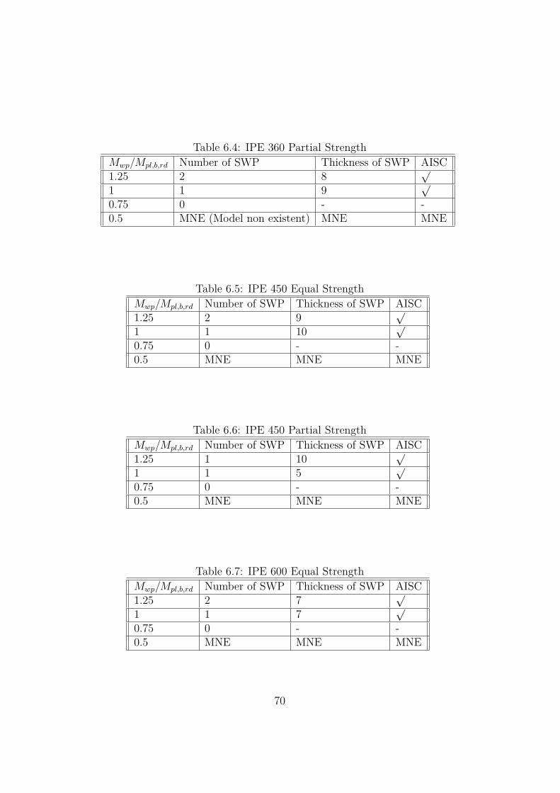
Table 6.4: IPE 360 Partial StrengthMwp/Mpl,b,rd Number of SWP Thickness of SWP AISC1.25 2 8
√
1 1 9√
0.75 0 - -0.5 MNE (Model non existent) MNE MNE
Table 6.5: IPE 450 Equal StrengthMwp/Mpl,b,rd Number of SWP Thickness of SWP AISC1.25 2 9
√
1 1 10√
0.75 0 - -0.5 MNE MNE MNE
Table 6.6: IPE 450 Partial StrengthMwp/Mpl,b,rd Number of SWP Thickness of SWP AISC1.25 1 10
√
1 1 5√
0.75 0 - -0.5 MNE MNE MNE
Table 6.7: IPE 600 Equal StrengthMwp/Mpl,b,rd Number of SWP Thickness of SWP AISC1.25 2 7
√
1 1 7√
0.75 0 - -0.5 MNE MNE MNE
70
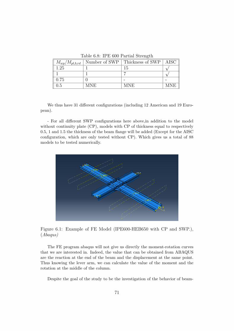
Table 6.8: IPE 600 Partial StrengthMwp/Mpl,b,rd Number of SWP Thickness of SWP AISC1.25 1 15
√
1 1 7√
0.75 0 - -0.5 MNE MNE MNE
We thus have 31 different configurations (including 12 American and 19 Euro-pean).
- For all different SWP configurations here above,in addition to the modelwithout continuity plate (CP), models with CP of thickness equal to respectively0.5, 1 and 1.5 the thickness of the beam flange will be added (Except for the AISCconfiguration, which are only tested without CP). Which gives us a total of 88models to be tested numerically.
Figure 6.1: Example of FE Model (IPE600-HEB650 with CP and SWP.),(Abaqus)
The FE program abaqus will not give us directly the moment-rotation curvesthat we are interested in. Indeed, the value that can be obtained from ABAQUSare the reaction at the end of the beam and the displacement at the same point.Thus knowing the lever arm, we can calculate the value of the moment and therotation at the middle of the column.
Despite the goal of the study to be the investigation of the behavior of beam-
71
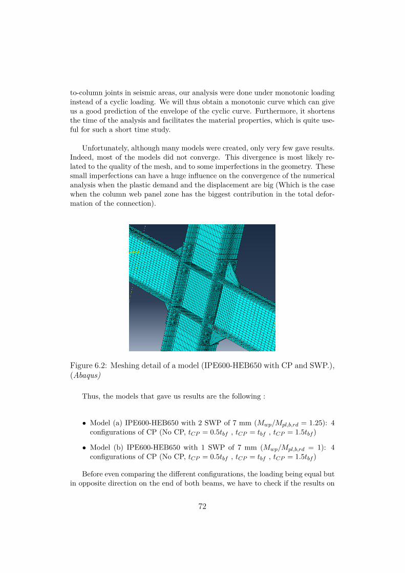
to-column joints in seismic areas, our analysis were done under monotonic loadinginstead of a cyclic loading. We will thus obtain a monotonic curve which can giveus a good prediction of the envelope of the cyclic curve. Furthermore, it shortensthe time of the analysis and facilitates the material properties, which is quite use-ful for such a short time study.
Unfortunately, although many models were created, only very few gave results.Indeed, most of the models did not converge. This divergence is most likely re-lated to the quality of the mesh, and to some imperfections in the geometry. Thesesmall imperfections can have a huge influence on the convergence of the numericalanalysis when the plastic demand and the displacement are big (Which is the casewhen the column web panel zone has the biggest contribution in the total defor-mation of the connection).
Figure 6.2: Meshing detail of a model (IPE600-HEB650 with CP and SWP.),(Abaqus)
Thus, the models that gave us results are the following :
• Model (a) IPE600-HEB650 with 2 SWP of 7 mm (Mwp/Mpl,b,rd = 1.25): 4configurations of CP (No CP, tCP = 0.5tbf , tCP = tbf , tCP = 1.5tbf )
• Model (b) IPE600-HEB650 with 1 SWP of 7 mm (Mwp/Mpl,b,rd = 1): 4configurations of CP (No CP, tCP = 0.5tbf , tCP = tbf , tCP = 1.5tbf )
Before even comparing the different configurations, the loading being equal butin opposite direction on the end of both beams, we have to check if the results on
72
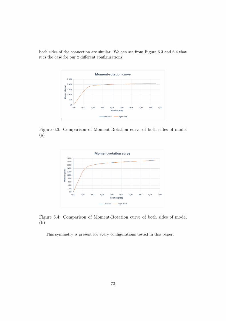
both sides of the connection are similar. We can see from Figure 6.3 and 6.4 thatit is the case for our 2 different configurations:
Figure 6.3: Comparison of Moment-Rotation curve of both sides of model(a)
Figure 6.4: Comparison of Moment-Rotation curve of both sides of model(b)
This symmetry is present for every configurations tested in this paper.
73
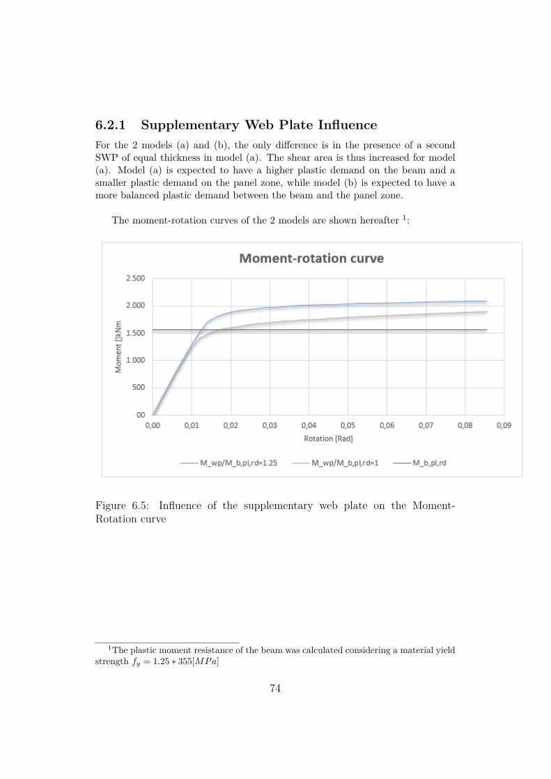
6.2.1 Supplementary Web Plate InfluenceFor the 2 models (a) and (b), the only difference is in the presence of a secondSWP of equal thickness in model (a). The shear area is thus increased for model(a). Model (a) is expected to have a higher plastic demand on the beam and asmaller plastic demand on the panel zone, while model (b) is expected to have amore balanced plastic demand between the beam and the panel zone.
The moment-rotation curves of the 2 models are shown hereafter 1:
Figure 6.5: Influence of the supplementary web plate on the Moment-Rotation curve
1The plastic moment resistance of the beam was calculated considering a material yieldstrength fy = 1.25 ∗ 355[MPa]
74
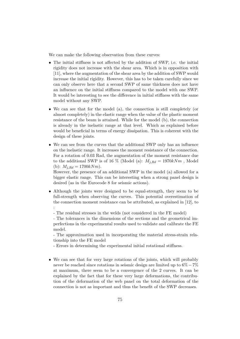
We can make the following observation from these curves:
• The initial stiffness is not affected by the addition of SWP, i.e. the initialrigidity does not increase with the shear area. Which is in opposition with[11], where the augmentation of the shear area by the addition of SWP wouldincrease the initial rigidity. However, this has to be taken carefully since wecan only observe here that a second SWP of same thickness does not havean influence on the initial stiffness compared to the model with one SWP.It would be interesting to see the difference in initial stiffness with the samemodel without any SWP.
• We can see that for the model (a), the connection is still completely (oralmost completely) in the elastic range when the value of the plastic momentresistance of the beam is attained. While for the model (b), the connectionis already in the inelastic range at that level. Which as explained beforewould be beneficial in terms of energy dissipation. This is coherent with thedesign of these joints.
• We can see from the curves that the additional SWP only has an influenceon the inelastic range. It increases the moment resistance of the connection.For a rotation of 0.03 Rad, the augmentation of the moment resistance dueto the additional SWP is of 16 % (Model (a): Mj,Rd = 1970kNm , Model(b): Mj,Rd = 1700kNm).However, the presence of an additional SWP in the model (a) allowed for abigger elastic range. This can be interesting when a strong panel design isdesired (as in the Eurocode 8 for seismic actions).
• Although the joints were designed to be equal-strength, they seem to befull-strength when observing the curves. This potential overestimation ofthe connection moment resistance can be attributed, as explained in [12], to:- The residual stresses in the welds (not considered in the FE model)- The tolerances in the dimensions of the sections and the geometrical im-perfections in the experimental results used to validate and calibrate the FEmodel.- The approximation used in incorporating the material stress-strain rela-tionship into the FE model- Errors in determining the experimental initial rotational stiffness.
• We can see that for very large rotations of the joints, which will probablynever be reached since rotations in seismic design are limited up to 6%−7%at maximum, there seem to be a convergence of the 2 curves. It can beexplained by the fact that for these very large deformations, the contribu-tion of the deformation of the web panel on the total deformation of theconnection is not as important and thus the benefit of the SWP decreases.
75
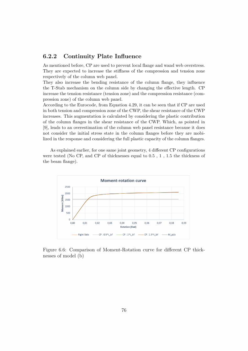
6.2.2 Continuity Plate InfluenceAs mentioned before, CP are used to prevent local flange and wand web overstress.They are expected to increase the stiffness of the compression and tension zonerespectively of the column web panel.They also increase the bending resistance of the column flange, they influencethe T-Stab mechanism on the column side by changing the effective length. CPincrease the tension resistance (tension zone) and the compression resistance (com-pression zone) of the column web panel.According to the Eurocode, from Equation 4.29, it can be seen that if CP are usedin both tension and compression zone of the CWP, the shear resistance of the CWPincreases. This augmentation is calculated by considering the plastic contributionof the column flanges in the shear resistance of the CWP. Which, as pointed in[9], leads to an overestimation of the column web panel resistance because it doesnot consider the initial stress state in the column flanges before they are mobi-lized in the response and considering the full plastic capacity of the column flanges.
As explained earlier, for one same joint geometry, 4 different CP configurationswere tested (No CP, and CP of thicknesses equal to 0.5 , 1 , 1.5 the thickness ofthe beam flange).
Figure 6.6: Comparison of Moment-Rotation curve for different CP thick-nesses of model (b)
76
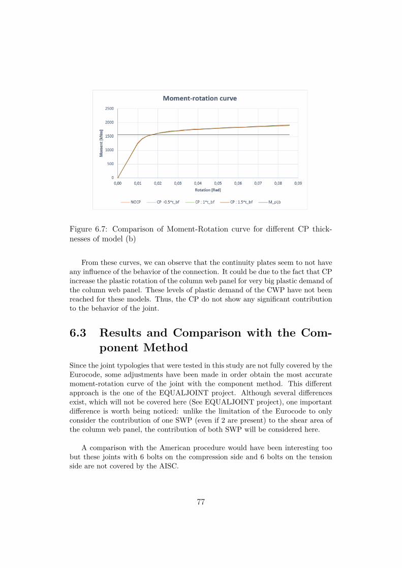
Figure 6.7: Comparison of Moment-Rotation curve for different CP thick-nesses of model (b)
From these curves, we can observe that the continuity plates seem to not haveany influence of the behavior of the connection. It could be due to the fact that CPincrease the plastic rotation of the column web panel for very big plastic demand ofthe column web panel. These levels of plastic demand of the CWP have not beenreached for these models. Thus, the CP do not show any significant contributionto the behavior of the joint.
6.3 Results and Comparison with the Com-ponent Method
Since the joint typologies that were tested in this study are not fully covered by theEurocode, some adjustments have been made in order obtain the most accuratemoment-rotation curve of the joint with the component method. This differentapproach is the one of the EQUALJOINT project. Although several differencesexist, which will not be covered here (See EQUALJOINT project), one importantdifference is worth being noticed: unlike the limitation of the Eurocode to onlyconsider the contribution of one SWP (even if 2 are present) to the shear area ofthe column web panel, the contribution of both SWP will be considered here.
A comparison with the American procedure would have been interesting toobut these joints with 6 bolts on the compression side and 6 bolts on the tensionside are not covered by the AISC.
77
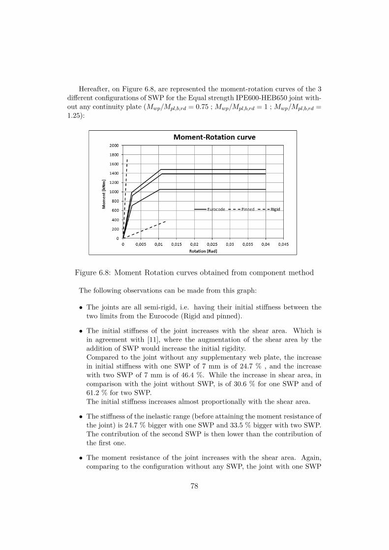
Hereafter, on Figure 6.8, are represented the moment-rotation curves of the 3different configurations of SWP for the Equal strength IPE600-HEB650 joint with-out any continuity plate (Mwp/Mpl,b,rd = 0.75 ; Mwp/Mpl,b,rd = 1 ; Mwp/Mpl,b,rd =1.25):
Figure 6.8: Moment Rotation curves obtained from component method
The following observations can be made from this graph:
• The joints are all semi-rigid, i.e. having their initial stiffness between thetwo limits from the Eurocode (Rigid and pinned).
• The initial stiffness of the joint increases with the shear area. Which isin agreement with [11], where the augmentation of the shear area by theaddition of SWP would increase the initial rigidity.Compared to the joint without any supplementary web plate, the increasein initial stiffness with one SWP of 7 mm is of 24.7 % , and the increasewith two SWP of 7 mm is of 46.4 %. While the increase in shear area, incomparison with the joint without SWP, is of 30.6 % for one SWP and of61.2 % for two SWP.The initial stiffness increases almost proportionally with the shear area.
• The stiffness of the inelastic range (before attaining the moment resistance ofthe joint) is 24.7 % bigger with one SWP and 33.5 % bigger with two SWP.The contribution of the second SWP is then lower than the contribution ofthe first one.
• The moment resistance of the joint increases with the shear area. Again,comparing to the configuration without any SWP, the joint with one SWP
78
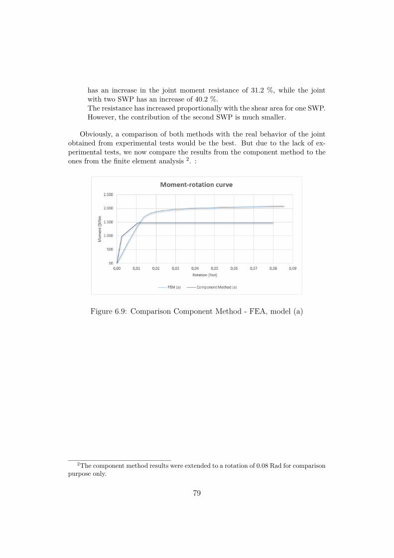
has an increase in the joint moment resistance of 31.2 %, while the jointwith two SWP has an increase of 40.2 %.The resistance has increased proportionally with the shear area for one SWP.However, the contribution of the second SWP is much smaller.
Obviously, a comparison of both methods with the real behavior of the jointobtained from experimental tests would be the best. But due to the lack of ex-perimental tests, we now compare the results from the component method to theones from the finite element analysis 2. :
Figure 6.9: Comparison Component Method - FEA, model (a)
2The component method results were extended to a rotation of 0.08 Rad for comparisonpurpose only.
79
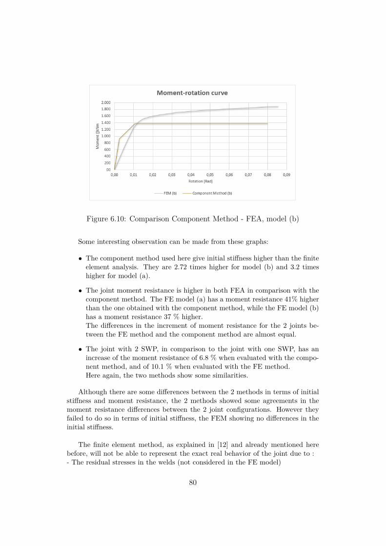
Figure 6.10: Comparison Component Method - FEA, model (b)
Some interesting observation can be made from these graphs:
• The component method used here give initial stiffness higher than the finiteelement analysis. They are 2.72 times higher for model (b) and 3.2 timeshigher for model (a).
• The joint moment resistance is higher in both FEA in comparison with thecomponent method. The FE model (a) has a moment resistance 41% higherthan the one obtained with the component method, while the FE model (b)has a moment resistance 37 % higher.The differences in the increment of moment resistance for the 2 joints be-tween the FE method and the component method are almost equal.
• The joint with 2 SWP, in comparison to the joint with one SWP, has anincrease of the moment resistance of 6.8 % when evaluated with the compo-nent method, and of 10.1 % when evaluated with the FE method.Here again, the two methods show some similarities.
Although there are some differences between the 2 methods in terms of initialstiffness and moment resistance, the 2 methods showed some agreements in themoment resistance differences between the 2 joint configurations. However theyfailed to do so in terms of initial stiffness, the FEM showing no differences in theinitial stiffness.
The finite element method, as explained in [12] and already mentioned herebefore, will not be able to represent the exact real behavior of the joint due to :- The residual stresses in the welds (not considered in the FE model)
80
- The tolerances in the dimensions of the sections and the geometrical imperfec-tions in the experimental results used to validate and calibrate the FE model.- The approximation used in incorporating the material stress-strain relationshipinto the FE model- Errors in determining the experimental initial rotational stiffness.
All these reasons play a role in the difference between the 2 methods compared.However, the component method is also an inexact method, i.e. it does not repre-sent the exact real behavior of the joint. Thus, as said before, further comparisonof these results with experimental tests on the joints analyzed would be extremelyinteresting.
81
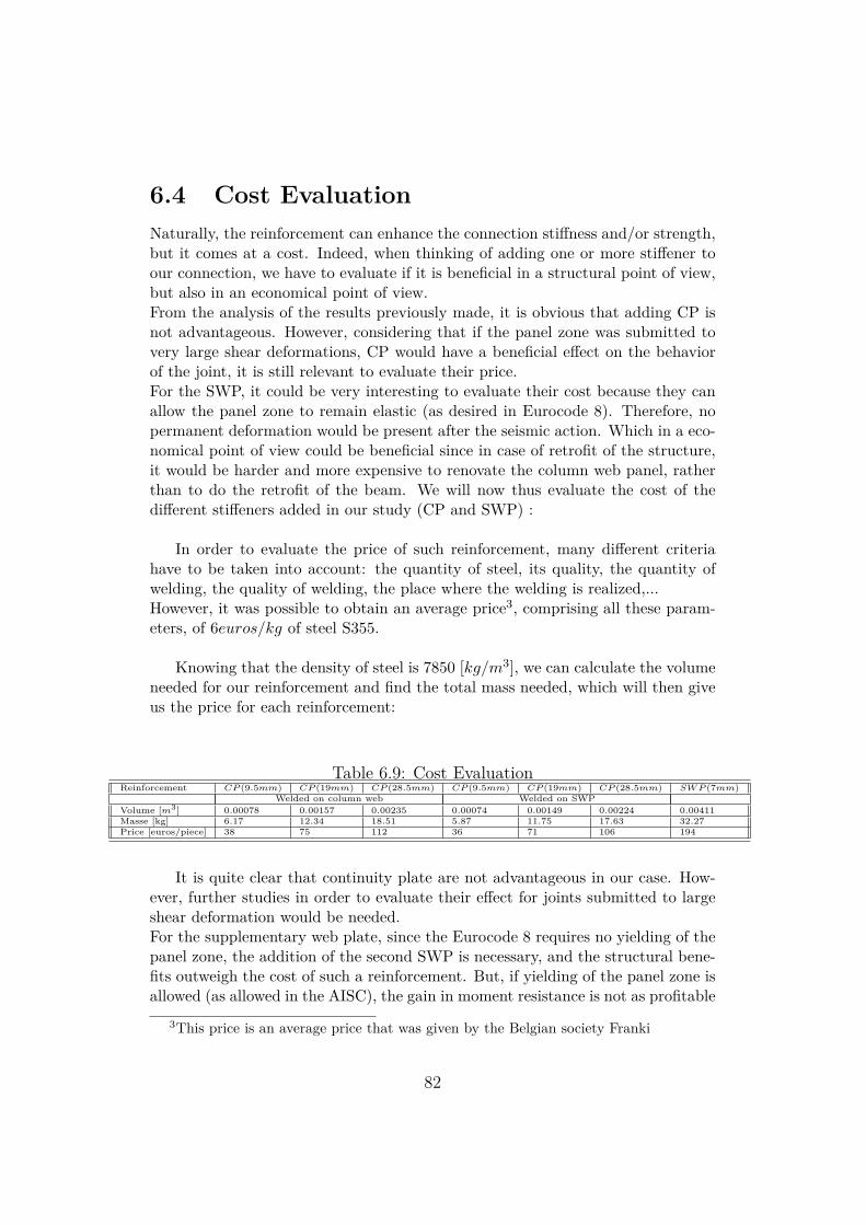
6.4 Cost EvaluationNaturally, the reinforcement can enhance the connection stiffness and/or strength,but it comes at a cost. Indeed, when thinking of adding one or more stiffener toour connection, we have to evaluate if it is beneficial in a structural point of view,but also in an economical point of view.From the analysis of the results previously made, it is obvious that adding CP isnot advantageous. However, considering that if the panel zone was submitted tovery large shear deformations, CP would have a beneficial effect on the behaviorof the joint, it is still relevant to evaluate their price.For the SWP, it could be very interesting to evaluate their cost because they canallow the panel zone to remain elastic (as desired in Eurocode 8). Therefore, nopermanent deformation would be present after the seismic action. Which in a eco-nomical point of view could be beneficial since in case of retrofit of the structure,it would be harder and more expensive to renovate the column web panel, ratherthan to do the retrofit of the beam. We will now thus evaluate the cost of thedifferent stiffeners added in our study (CP and SWP) :
In order to evaluate the price of such reinforcement, many different criteriahave to be taken into account: the quantity of steel, its quality, the quantity ofwelding, the quality of welding, the place where the welding is realized,...However, it was possible to obtain an average price3, comprising all these param-eters, of 6euros/kg of steel S355.
Knowing that the density of steel is 7850 [kg/m3], we can calculate the volumeneeded for our reinforcement and find the total mass needed, which will then giveus the price for each reinforcement:
Table 6.9: Cost EvaluationReinforcement CP (9.5mm) CP (19mm) CP (28.5mm) CP (9.5mm) CP (19mm) CP (28.5mm) SWP (7mm)
Welded on column web Welded on SWPVolume [m3] 0.00078 0.00157 0.00235 0.00074 0.00149 0.00224 0.00411Masse [kg] 6.17 12.34 18.51 5.87 11.75 17.63 32.27Price [euros/piece] 38 75 112 36 71 106 194
It is quite clear that continuity plate are not advantageous in our case. How-ever, further studies in order to evaluate their effect for joints submitted to largeshear deformation would be needed.For the supplementary web plate, since the Eurocode 8 requires no yielding of thepanel zone, the addition of the second SWP is necessary, and the structural bene-fits outweigh the cost of such a reinforcement. But, if yielding of the panel zone isallowed (as allowed in the AISC), the gain in moment resistance is not as profitable
3This price is an average price that was given by the Belgian society Franki
82
since in both cases the moment resistance of the joint is larger than the flexuralresistance of the adjacent beam. Again, further study in order to evaluate thegain obtained from the configuration without any SWP would be relevant. Andadditional study on the benefits of SWP on weaker panel zone (weaker column)would also be interesting.
83
Chapter 7
Conclusion
In this study, one bolted extended stiffened joint (IPE600-HEB650)has been testednumerically under monotonic loading. Different reinforcements have been added(Continuity plate and supplementary web plate) in order to investigate their in-fluence on the column web panel zone.Some conclusions could be made from the results:
• For the joint investigated, the CP did not have any significant influence.However, this is most probably due to the small shear deformation that thecolumn web panel are submitted to (strong column having one or two SWP).Therefore, further studies on weaker column (other joint configurations) andon the same column without any SWP would be needed in order to evaluatethe influence of the CP.
• The addition of the second SWP on the joint investigated increased themoment resistance of the joint, but did not have any influence on the initialstiffness. It allowed the increase of the elastic range of the joint, which canbe interesting when the designer does not want the panel zone to yield (Asdesired in Eurocode 8 [3]).However additional studies in order to compare the results obtained withthe same joint without any SWP would be interesting. As well as othernumerical analysis on other joint geometry.
• The finite element analysis showed an overestimation of the moment resis-tance obtained by the FEA and an underestimation of the initial stiffness,in comparison with the component method.However, none of these methods describes exactly the real behavior of thejoint.Therefore, experimental tests on the joints analyzed would allow a betterunderstanding of the limitations of the two methods used in this study.
84
List of Figures
3.1 Advantages and disadvantages of models to obtain the rotationaljoint behaviour.), ([13]) . . . . . . . . . . . . . . . . . . . . . . . . 12
3.2 Principal characteristics of current models to obtain the rotationalbehaviour of a joint.), ([13]) . . . . . . . . . . . . . . . . . . . . . 12
3.3 Geometries of J1 and J3 series), ([10]) . . . . . . . . . . . . . . . . 143.4 Connections chosen for the EVD determination), ([10]) . . . . . . 143.5 Cyclic behavior and failure mode of cyclic specimens, 1), ([11]) . . 153.6 Cyclic behavior and failure mode of cyclic specimens, 2), ([11]) . . 163.7 Description of the CWP Tests), ([11]) . . . . . . . . . . . . . . . . 163.8 Different mathematical representations of the (Mj − Θ) curve: (a)
linear; (b) bi-linear; (c) multi-linear (tri-linear); (d) nonlinear.),([13]) . . . . . . . . . . . . . . . . . . . . . . . . . . . . . . . . . . 18
3.9 Moment-Rotation Envelopes, ([14]) . . . . . . . . . . . . . . . . . 193.10 Comparison between Experimental and Computed Curves, ([14]) 193.11 Joint Modeling Reflecting (a) Actual Behavior and (b) Simplified
Modeling, ([14]) . . . . . . . . . . . . . . . . . . . . . . . . . . . . 203.12 Identification of dissipative components, ([19]) . . . . . . . . . . . 213.13 EEP-CYC 01 Moment-Rotation curve, ([19]) . . . . . . . . . . . . 223.14 Energy dissipation of specimen EEP-CYC 01, ([19]) . . . . . . . . 233.15 Comparison between model and experimental dissipated energy,
([20]) . . . . . . . . . . . . . . . . . . . . . . . . . . . . . . . . . . 243.16 Hysteretic moment-rotation (M − Φ) model of the extended end-
plate connection, ([23]) . . . . . . . . . . . . . . . . . . . . . . . . 253.17 Joint rotation definition , ([23]) . . . . . . . . . . . . . . . . . . . 25
4.1 Four-bolt stiffened configuration, (Chapter 6, [4]) . . . . . . . . . 274.2 Four-bolt stiffened geometry, (Chapter 6, [4]) . . . . . . . . . . . . 284.3 Summary of Four-Bolt Extended Stiffened End-Plate Yield Line
Mechanism Parameter, (Chapter 6, [4]) . . . . . . . . . . . . . . . 294.4 Summary of Four-Bolt Extended Column Flange Yield Line Mech-
anism Parameter, (Chapter 6, [4]) . . . . . . . . . . . . . . . . . . 314.5 Classification of joints by stiffness, (Chapter 5, [2]) . . . . . . . . 364.6 Full Strength Joint, (Chapter 5, [2]) . . . . . . . . . . . . . . . . . 374.7 Type of Joint Model, (Chapter 5, [2]) . . . . . . . . . . . . . . . . 37
85
4.8 Joints components to be evaluated, (Chapter 2, [30]) . . . . . . . 384.9 Connection Geometry, (Chapter 2, [30]) . . . . . . . . . . . . . . . 394.10 T-Stub Failure Modes, ([31]) . . . . . . . . . . . . . . . . . . . . . 414.11 Length of Equivalent T-stub of a Stiffened Column Flange in Bend-
ing, ([31]) . . . . . . . . . . . . . . . . . . . . . . . . . . . . . . . . 414.12 Transformation parameter β, (Chapter 5,[2]) . . . . . . . . . . . . 434.13 Effective Width β, ([30]) . . . . . . . . . . . . . . . . . . . . . . . 444.14 Shear forces in Column Web Panel, ([30]) . . . . . . . . . . . . . . 454.15 Tension and compression resistances contributing to moment resis-
tance, ([30]) . . . . . . . . . . . . . . . . . . . . . . . . . . . . . . 464.16 Tension and shear bolts, ([30]) . . . . . . . . . . . . . . . . . . . . 474.17 Spring model for multi bolt-rows end-plate joints, ([31]) . . . . . . 484.18 Principal stress distribution in the rib, ([29]) . . . . . . . . . . . . 504.19 Definition of rib cross section, ([29]) . . . . . . . . . . . . . . . . . 524.20 Equivalent stress model, ([29]) . . . . . . . . . . . . . . . . . . . . 524.21 Supplementary web plate, (Chapter 6, [2]) . . . . . . . . . . . . . 54
5.1 Details of the setup), ([25]) . . . . . . . . . . . . . . . . . . . . . . 565.2 Section AA’ of setup, ([28]) . . . . . . . . . . . . . . . . . . . . . . 565.3 Plastic stress - strain diagram for S355, ([33]) . . . . . . . . . . . . 595.4 Plastic stress - strain diagram for Bolts 10.9, ([33]) . . . . . . . . . 595.5 Difference between nominal and net area of several bolt types, ([33]) 605.6 Meshed Bolt, ([33]) . . . . . . . . . . . . . . . . . . . . . . . . . . . 605.7 ABAQUS Model (For the current project) . . . . . . . . . . . . . . 615.8 Bolt load definition and the effect of Clamping on the End Plate, [33] 625.9 Test Specimen and loading arrangement, [25] . . . . . . . . . . . . 635.10 Details of connection, [25] . . . . . . . . . . . . . . . . . . . . . . . 645.11 Detailed dimensions of the connection, [25] . . . . . . . . . . . . . 645.12 Material Properties, [25] . . . . . . . . . . . . . . . . . . . . . . . . 645.13 Failure mode comparison between experimental and FEA (Case
1),Experimental : [25] , FEA : [33] . . . . . . . . . . . . . . . . . . 655.14 Moment-rotation curve comparison (Case 1), [25] . . . . . . . . . . 655.15 Failure mode comparison between experimental and FEA (Case
2),Experimental : [25] , FEA : [33] . . . . . . . . . . . . . . . . . . 665.16 Moment-rotation curve comparison (Case 2), [25] . . . . . . . . . . 66
6.1 Example of FEModel (IPE600-HEB650 with CP and SWP.), (Abaqus)71
6.2 Meshing detail of a model (IPE600-HEB650 with CP and SWP.),(Abaqus) . . . . . . . . . . . . . . . . . . . . . . . . . . . . . . . . 72
6.3 Comparison of Moment-Rotation curve of both sides of model (a) . 736.4 Comparison of Moment-Rotation curve of both sides of model (b) . 736.5 Influence of the supplementary web plate on the Moment-Rotation
curve . . . . . . . . . . . . . . . . . . . . . . . . . . . . . . . . . . . 74
86
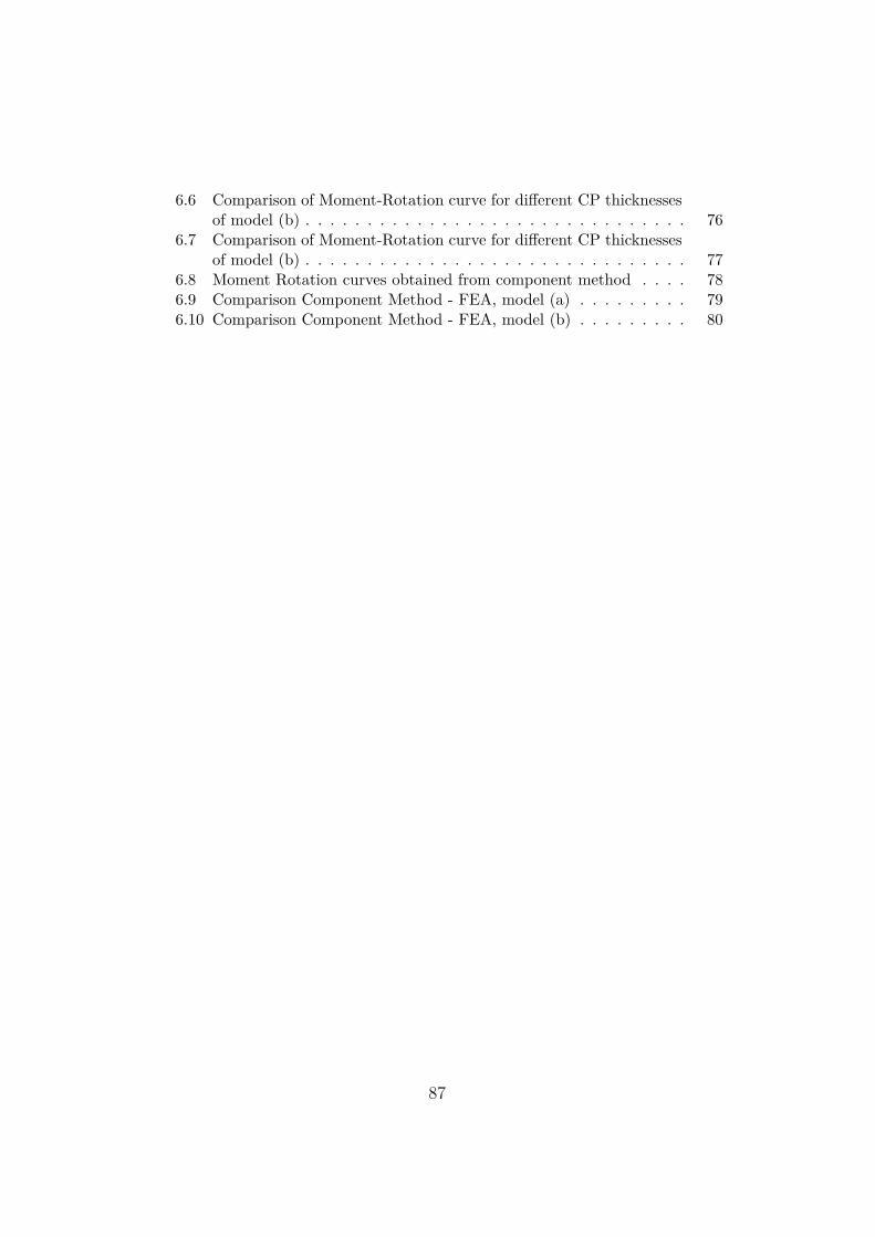
6.6 Comparison of Moment-Rotation curve for different CP thicknessesof model (b) . . . . . . . . . . . . . . . . . . . . . . . . . . . . . . . 76
6.7 Comparison of Moment-Rotation curve for different CP thicknessesof model (b) . . . . . . . . . . . . . . . . . . . . . . . . . . . . . . . 77
6.8 Moment Rotation curves obtained from component method . . . . 786.9 Comparison Component Method - FEA, model (a) . . . . . . . . . 796.10 Comparison Component Method - FEA, model (b) . . . . . . . . . 80
87
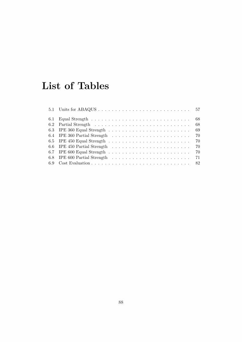
List of Tables
5.1 Units for ABAQUS . . . . . . . . . . . . . . . . . . . . . . . . . . . 57
6.1 Equal Strength . . . . . . . . . . . . . . . . . . . . . . . . . . . . . 686.2 Partial Strength . . . . . . . . . . . . . . . . . . . . . . . . . . . . 686.3 IPE 360 Equal Strength . . . . . . . . . . . . . . . . . . . . . . . . 696.4 IPE 360 Partial Strength . . . . . . . . . . . . . . . . . . . . . . . 706.5 IPE 450 Equal Strength . . . . . . . . . . . . . . . . . . . . . . . . 706.6 IPE 450 Partial Strength . . . . . . . . . . . . . . . . . . . . . . . 706.7 IPE 600 Equal Strength . . . . . . . . . . . . . . . . . . . . . . . . 706.8 IPE 600 Partial Strength . . . . . . . . . . . . . . . . . . . . . . . 716.9 Cost Evaluation . . . . . . . . . . . . . . . . . . . . . . . . . . . . . 82
88
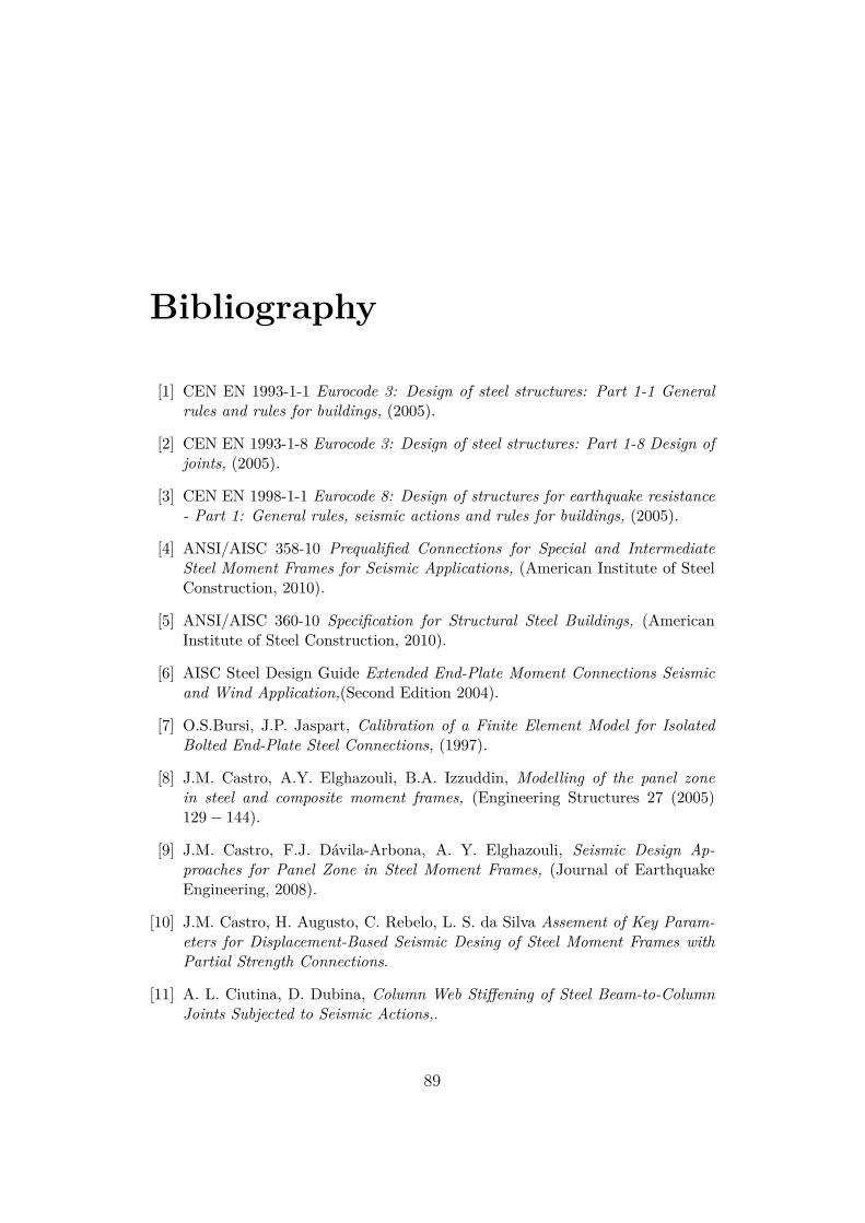
Bibliography
[1] CEN EN 1993-1-1 Eurocode 3: Design of steel structures: Part 1-1 Generalrules and rules for buildings, (2005).
[2] CEN EN 1993-1-8 Eurocode 3: Design of steel structures: Part 1-8 Design ofjoints, (2005).
[3] CEN EN 1998-1-1 Eurocode 8: Design of structures for earthquake resistance- Part 1: General rules, seismic actions and rules for buildings, (2005).
[4] ANSI/AISC 358-10 Prequalified Connections for Special and IntermediateSteel Moment Frames for Seismic Applications, (American Institute of SteelConstruction, 2010).
[5] ANSI/AISC 360-10 Specification for Structural Steel Buildings, (AmericanInstitute of Steel Construction, 2010).
[6] AISC Steel Design Guide Extended End-Plate Moment Connections Seismicand Wind Application,(Second Edition 2004).
[7] O.S.Bursi, J.P. Jaspart, Calibration of a Finite Element Model for IsolatedBolted End-Plate Steel Connections, (1997).
[8] J.M. Castro, A.Y. Elghazouli, B.A. Izzuddin, Modelling of the panel zonein steel and composite moment frames, (Engineering Structures 27 (2005)129− 144).
[9] J.M. Castro, F.J. Dávila-Arbona, A. Y. Elghazouli, Seismic Design Ap-proaches for Panel Zone in Steel Moment Frames, (Journal of EarthquakeEngineering, 2008).
[10] J.M. Castro, H. Augusto, C. Rebelo, L. S. da Silva Assement of Key Param-eters for Displacement-Based Seismic Desing of Steel Moment Frames withPartial Strength Connections.
[11] A. L. Ciutina, D. Dubina, Column Web Stiffening of Steel Beam-to-ColumnJoints Subjected to Seismic Actions,.
89
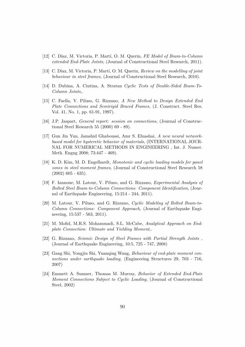
[12] C. Díaz, M. Victoria, P. Martí, O. M. Querin, FE Model of Beam-to-Columnextended End-Plate Joints, (Journal of Constructional Steel Research, 2011).
[13] C. Díaz, M. Victoria, P. Martí, O. M. Querin, Review on the modelling of jointbehaviour in steel frames, (Journal of Constructional Steel Research, 2010).
[14] D. Dubina, A. Ciutina, A. Stratan Cyclic Tests of Double-Sided Beam-To-Column Joints,.
[15] C. Faella, V. Piluso, G. Rizzano, A New Method to Design Extended EndPlate Connections and Semirigid Braced Frames, (J. Construct. Steel Res.Vol. 41, No. 1, pp. 61-91, 1997).
[16] J.P. Jaspart, General report: session on connections, (Journal of Construc-tional Steel Research 55 (2000) 69 - 89).
[17] Gun Jin Yun, Jamshid Ghaboussi, Amr S. Elnashai, A new neural network-based model for hysteretic behavior of materials, (INTERNATIONAL JOUR-NAL FOR NUMERICAL METHODS IN ENGINEERING , Int. J. Numer.Meth. Engng 2008; 73:447 - 469).
[18] K. D. Kim, M. D. Engelhardt, Monotonic and cyclic loading models for panelzones in steel moment frames, (Journal of Constructional Steel Research 58(2002) 605 - 635).
[19] F. Iannone, M. Latour, V. Piluso, and G. Rizzano, Experimental Analysis ofBolted Steel Beam-to-Column Connections: Component Identification, (Jour-nal of Earthquake Engineering, 15:214 - 244, 2011).
[20] M. Latour, V. Piluso, and G. Rizzano, Cyclic Modeling of Bolted Beam-to-Column Connections: Component Approach, (Journal of Earthquake Engi-neering, 15:537 - 563, 2011).
[21] M. Mofid, M.R.S. Mohammadi, S.L. McCabe, Analytical Approach on End-plate Connection: Ultimate and Yielding Moment,.
[22] G. Rizzano, Seismic Design of Steel Frames with Partial Strength Joints ,(Journal of Earthquake Engineering, 10:5, 725 - 747, 2008)
[23] Gang Shi, Yongjiu Shi, Yuanqing Wang, Behaviour of end-plate moment con-nections under earthquake loading, (Engineering Structures 29, 703 - 716,2007)
[24] Emmett A. Sumner, Thomas M. Murray, Behavior of Extended End-PlateMoment Connections Subject to Cyclic Loading, (Journal of ConstructionalSteel, 2002)
90
[25] Y. Shi, G. Shi, Y. Wang, Experimental and theoretical analysis of the moment-rotation behaviour of stiffened extended end-plate connections, (Journal ofConstructional Steel Research 63, 1279 - 1293, 2007)
[26] G.Terracciano, G. Della Corte, G. Di Lorenzo, R. Landolfo, Simplified Meth-ods of Analysis for End-Plate Beam-to-Column Joints,
[27] Meng Wang, Yongjiu Shi, Yuanqing Wang, Gang Shi, Numerical study onseismic behaviors of steel frame end-plate connections, (Journal of Construc-tional Steel Research 90 (2013) 140 - 152)
[28] M. Zimbru, Numerical Investigation of Seismic Behavior of Steel StiffenedExtended End Plate Connections (2015).
[29] Lee C-H, Seismic design of rib-reinforced steel moment connections based onequivalent strut model,(Journal of Structural Engineering,September 2002,128; 1121 - 1129).
[30] Steel Construction Institute, The British Constructional Steelwork Associa-tion Limited Joints in Steel Construction : Moment-Resisting Joints to Eu-rocode 3.
[31] Adam, SKILLS - Steel construction industry lifelong learning supportMomentConnections - Part 1.
[32] SIMULIA Abaqus-CAE User’s Manual.
[33] R. Landolfo, M. D’Aniello, R. Tartaglia, S. Costanzo, G. Ambrosino, Proce-dures and Assumptions and Definition of Numerical Quality Control Proce-dures,(University of Naples Federico II, 2015).
[34] G. Brandonisio, A. De Luca, E. Mele, Shear strength of panel zone in beam-to-column connections,(University of Naples Federico II, 2011).
91

Nomenclature
β transformation parameter
η equivalent strut area factor
γM0 the partial safety factor for resistance of cross-sections
γM1 partial safety factor for resistance of members
γM2 the partial safety factor for bolts
ω reduction factor to allow for the interaction with shear in the column webpanel (EN 1993-1-8 Table 6.3)
ρ reduction factor for plate buckling (EN 1993-1-8 6.2.6.2(1))
θcom,Ed the maximum coexisting longitudinal compression stress in the columnweb (due to axial force and bending moment). In most of the cases, thereduction factor is equal to 1. However, it can conservatively be taken as0.7.
AB nominal cross sectional area of the selected bolt diameter
Ac column cross-sectional area
As tensile stress area of the bolt
ABe Effective area of the threads
Aeffective area of the threaded region
Agross gross cross section of the shank
Avc shear area of the column (For rolled I and H sections)
b Base
beff,c,wc effective width of the column web in compression
92

beff,t,wb effective width of the beam web in tension; it is equal to the effectivelength of equivalent T-stub representing the end-plate in bending for anindividual bolt-row or bolt-group
beff,t,wc effective width of the column web in tension (for a single bolt-row); It istaken as equal to the smallest of the effective lengths leff (individually oras a part of group of bolts) given in EN 1993-1-8 § 6.2.6.3 Table 6.5
beff,t,wc effective width of the column web in tension; for bolted connection it isequal to the effective length of equivalent T-stub representing the columnflange
d0 hole diameter for a bolt
dB nominal diameter of the bolt
db beam depth
dc depth of the column
ds distance between the centerlines of the stiffeners
E the Young’s modulus
e1 end distance from the center of a bolt hole to the adjacent end of any part
f stiffness correlation factor taken as 0.55
Fi specified LFRD bolt tensile strength
Fu specified minimum tensile strength of end-plate of column flange material
fu ultimate tensile strength of the material of either: the end-plate or thecolumn flange
Fv nominal shear strength of bolts Table J3.2 of the AISC LRFD Specification(AISC, 1999)
factual actual stress
Fc column flange material yield strength
feffective effective stress
Ft,ep,Rd End-plate in bending resistance
Ft,fc,Rd Column flange in bending resistance
Ft,Rd design tension resistance of bolt
93

Ft,wb,Rd Beam web in tension resistance
Ft,wc,Rd Column web in transverse tension resistance
fub ultimate tensile strength for the bolt
Fyb specified minimum yield stress of beam material
Fyp end-plate material yield strength
Fyr yield strength of the rib
Fys specified minimum yield stress of stiffener material
h depth of the section; for haunched beam, it is the depth of the fabricatedsection
hi distance from the centerline of the beam compression flange to the center-line of the ith tension bolt row
hr distance between bolt-row r and the center of compression
hst stiffener height
Ib moment of inertia of the beam about the strong axis
kb Elastic stiffens of the bolt
kc distance from outer face of the column flange to web toe of fillet
keff,r effective stiffness coefficient for bolt-row r taking into account the stiffnesski for the basic components
keq equivalent stiffness coefficient
kwc reduction factor (EN 1993-1-8 6.2.6.2(2))
Lb bolt elongation length, taken as equal to the grip length (total thickness ofmaterial and washers), plus half the sum of the height of the bolt head andthe height of the nut
Lc clear distance, in the direction of the force, between the edge of the holeand the edge of the adjacent hole or edge of the material
Ls Length of the bolt shank
leff ′ smallest of the effective lengths l′eff (individually or as a part of group ofbolts) given for this bolt-row given in EN 1993-1-8 §6.2.6.5 Table 6.6
94

leff smallest of the effective lengths leff (individually or as a part of group ofbolts) given for this bolt-row given in EN 1993-1-8 § 6.2.6.3 Table 6.5
Ltg Length of the threaded portion
Mc,Rd design moment resistance of beam cross-section,reduced if necessary to al-low for shear (EN 1993-1-1 6.2.5)
Mj,Rd Design plastic moment resistance of the joint
Mpl,b,rd design plastic moment resistance of Beam
Mpl,fc,Rd design plastic moment resistance of a column flange
Mpl,st,Rd design plastic moment resistance of a stiffener
Muc moment at the face of the column
Mwp Moment resistance of ColumnWeb Panel (Shear resistance times lever arm)
N thickness of beam flange plus 2 times the groove weld reinforcement leg size
N ′ normal interaction force
nb number of bolts at the compression flange
ni number of inner bolts
no number of outer bolts
p1 spacing between centers of bolts in a line
Pr Required strength
Py axial yield strength of the column
Q tangential interaction force
sf leg length of the fillet weld between the compression flange and the endplate
tf thickness of an equivalent T-stub flange (tf = tfc or tf = tp)
tp end-plate thickness
tfb beam flange thickness
tfc column flange thickness
twb beam web thickness
95
twc column web thickness
Vu shear at the plastic hinge
Vbw,Rd the shear buckling resistance of the web
Yp end-plate yield line mechanism parameter obtained from Figure 4.3
Y ′p column flange yield line mechanism parameter obtained from Figure 4.4
z lever arm
zeq equivalent lever arm
96