experimental investigation of rc beam column joint ... · the reinforcement details of beam column...
TRANSCRIPT

INTERNATIONAL JOURNAL OF CIVIL AND STRUCTURAL ENGINEERING Volume 1, No 1, 2010
© Copyright 2010 All rights reserved Integrated Publishing services Research Article ISSN 0976 – 4399
35
Experimental Investigation of RCBeam Column Joint Strengthening by FPP Wrapping
1 N.Vijayalakshmi 2 M.Kalaivani 3 A.Murugesan 4 G.S.Thirugnanam
1,2 P.GStudent. Institute of Road and Transport Technology 3 Research Scholar, Sona College of technology
4 Assistant Professor and Head, Institute of Road and Transport Technology
ABSTRACT
Beamcolumn joints of a reinforced concrete structure need special attention due to their highly complex behavior under seismic loads, which is marked by a combination of large shear forces, diagonal tension and high bond stresses in the reinforcement bars, all brittle mode of failure. An experimental investigation of the behavior of Corner beamcolumn joints with detailing as per IS 13920: 1993 under seismic conditions is presented in this paper. The experimental study on Corner beamcolumn joint of a multistory reinforced concrete building (G+ 4 storey’s) in Salem Zone falling under the seismic Zone – III has been analyzed using STADD.pro. The specimens were designed for seismic load according to IS 1893(PartI): 2002 & IS 13920: 1993. The test specimen is reduced to one fifth model of beam column joint from prototype specimen. Column confinement and beam stirrups are provided closely in joint region according to IS 13920: 1993.The test specimens were evaluated in terms of loaddisplacement relation, ductility, load ratio and cracking pattern.
Keywords : Rehabilitation, Strengthening beam column joint, FRP wrapping,
1 Introduction In RC buildings, portions of columns that are common to beams at their intersections are
called beamcolumn joints. Since their constituent materials have limited strengths, the joints have limited force carrying capacity. When forces larger than these are applied during earthquakes, joints are severely damaged. Repairing damaged joints is difficult, and so damage must be avoided. Thus, beamcolumn joints must be designed to resist earthquake effects. Under earthquake shaking, the beams adjoining a joint are subjected to moments in the same (clockwise or counterclockwise) direction. Under these moments, the top bars in the beamcolumn joint are pulled in one direction and the bottom ones in the opposite direction. These forces are balanced by bond stress developed between concrete and steel in the joint region. If the column is not wide enough or if the strength of concrete in the joint is low, there is insufficient grip of concrete on the steel bars. In such circumstances, the bar slips inside the joint region, and beams lose their capacity to carry load. Further, under the action of the above pullpush forces at top and bottom ends, joints undergo geometric distortion; one diagonal length of the joint elongates and the other compresses.

INTERNATIONAL JOURNAL OF CIVIL AND STRUCTURAL ENGINEERING Volume 1, No 1, 2010
© Copyright 2010 All rights reserved Integrated Publishing services Research Article ISSN 0976 – 4399
36
Problems of diagonal cracking and crushing of concrete in the joint region can be controlled by two mean, namely providing large column sizes and providing closely spaced closedloop steel ties around column bars in the joint region. The ties hold together the concrete in the joint and also resist shear force, thereby reducing the cracking and crushing of concrete. Providing closedloop ties in the joint requires some extra effort. Indian Standard IS 13920: 1993 recommends continuing the transverse loops around the column bars through the joint region. In practice, this is achieved by preparing the cage of the reinforcement (both longitudinal bars and stirrups) of all beams at a floor level to be prepared on top of the beam formwork of that level and lowered into the cage. However, this may not always be possible particularly when the beams are long and the entire reinforcement cage becomes heavy.
1.1 Strengthening Of Beam Column Joints By Ductile Detailing As Per Is 13920: 1993 The reinforcement details of beam column joint in pre1970 buildings, the longitudinal
reinforcement in beam is discontinuous and in columns the reinforcement is lap spliced with short length above the floor level. The transverse reinforcement is not proportioned to prevent the shear or lapspliced in joints, and the details show wide spacing, open stirrups, and hoops with 90degree bends. No joint transverse reinforcement is observed. These deficiencies reduce the joint strength and lateral displacement ductility. Failures in RC buildings during earthquakes demonstrate that brittle shear failure of beam column joints lead to total collapse. In order to strengthen the weak elements, various retrofit schemes could be designed. Recently, a simplified analytical model for the joint behavior has been proposed as a viable tool for extensive parametrical studies on seismic response of the existing buildings. Several techniques were employed to strengthen the beam column joints including concrete jackets, bolted steel plates and jacketing with corrugated steel sheets. These strengthening approaches have been found to improve the joint shear strength and ductility. However, a major difficulty in strengthening of beam column joints is ensuring effective confinement in the joint region.
In Corner joints the beam longitudinal reinforcement that frames into the column terminates within the joint core. After a few cycles of inelastic loading, the bond deterioration initiated at the column face due to yield penetration and splitting cracks, progresses towards the joint core. Repeated loading will aggravate the situation and a complete loss of bond up to the beginning of the bent portion of the bar may take place. The longitudinal reinforcement bar, if terminating straight, will get pulled out due to progressive loss of bond. The pull out failure of the longitudinal bars of the beam results in complete loss of flexural strength. This kind of failure is unacceptable at any stage. Hence, proper anchorage of the beam longitudinal reinforcement bars in the joint core is of utmost importance. The pull out failure of bars in exterior joints can be prevented by the provision of hooks or by some positive anchorage. Hooks are helpful in providing adequate anchorage when furnished with sufficient horizontal development length and a tail extension. Because of the likelihood of yield penetration into the joint core, the development length is to be considered effective from the critical section beyond the zone of yield penetration. Thus, the size of the member should accommodate the development length considering the possibility of yield penetration. When the reinforcement is subjected to compression, the tail end of hooks is not generally helpful to cater to the requirements of development length in compression. However, the horizontal ties in the form of transverse

INTERNATIONAL JOURNAL OF CIVIL AND STRUCTURAL ENGINEERING Volume 1, No 1, 2010
© Copyright 2010 All rights reserved Integrated Publishing services Research Article ISSN 0976 – 4399
37
reinforcement in the joint provide effective restraints against the hook when the beam bar is in compression.
1.2 Strengthening By Gfrp In Beam Column Joints The GFRP jacketing enhances the shear strength of joint and improves the ductility of the
joint. GFRP sheets wrapped around the joint to prevent the joint shear failure, and attached to the beam bottom face to strengthen inadequately anchored steel bars. The joints built without proper Reinforcement detailing suffered brittle shear and bond failures while the rehabilitated joints improved the ductility. GFRP composites posses’ high strength to weight ratio and tensile strength compared to Tor steel. The other enhancing properties of GFRP are it is non reactive for chemicals such as chlorides, alkalis and thermally non conductive in nature and hence durability of structure is increased. This calls for the use of GFRP as reinforcement for concrete structures in which corrosion is primary concern. GFRP composites mats, fabrics and rods can be effectively applied externally and internally over the RC elements for strengthening purposes. Such strengthening leads to improved ductility, energy absorption capacity and increased load carrying capacity of the RC members. These composites are, hence used in larger scale for the rehabilitation of earthquake affected structures.
2 Experimental Investigation A two bay five storey Reinforced concrete frames has been designed for seismic loads
according to IS 1893 and IS 13920. In this experiment study, loading was applied in forward and reverse cyclic loading and strengthening of beam column joint after post yielding using FRP Wrapping and behavior of joint is studied up to failure loading condition.
2.1 Details Of Specimen The test specimen was reduced to 1/5 th scale to suit the loading arrangement and test
facilities. For testing model, the dimension of beam was 120 X 170 mm and beam length of 450mm and that column size was 120 X 230 mm. Height of the column was 375mm. The Fig1 shows the shape of form work and reinforcement details for test specimen.
Fig 1: Formwork and Reinforcement for test specimen
2.2 Reinforcement Details
INTERNATIONAL JOURNAL OF CIVIL AND STRUCTURAL ENGINEERING Volume 1, No 1, 2010
© Copyright 2010 All rights reserved Integrated Publishing services Research Article ISSN 0976 – 4399
38
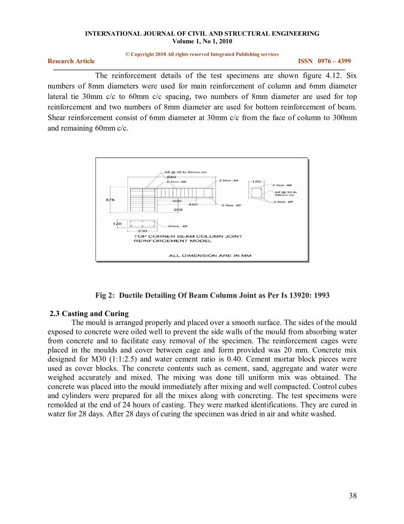
The reinforcement details of the test specimens are shown figure 4.12. Six numbers of 8mm diameters were used for main reinforcement of column and 6mm diameter lateral tie 30mm c/c to 60mm c/c spacing, two numbers of 8mm diameter are used for top reinforcement and two numbers of 8mm diameter are used for bottom reinforcement of beam. Shear reinforcement consist of 6mm diameter at 30mm c/c from the face of column to 300mm and remaining 60mm c/c.
Fig 2: Ductile Detailing Of Beam Column Joint as Per Is 13920: 1993
2.3 Casting and Curing The mould is arranged properly and placed over a smooth surface. The sides of the mould
exposed to concrete were oiled well to prevent the side walls of the mould from absorbing water from concrete and to facilitate easy removal of the specimen. The reinforcement cages were placed in the moulds and cover between cage and form provided was 20 mm. Concrete mix designed for M30 (1:1:2.5) and water cement ratio is 0.40. Cement mortar block pieces were used as cover blocks. The concrete contents such as cement, sand, aggregate and water were weighed accurately and mixed. The mixing was done till uniform mix was obtained. The concrete was placed into the mould immediately after mixing and well compacted. Control cubes and cylinders were prepared for all the mixes along with concreting. The test specimens were remolded at the end of 24 hours of casting. They were marked identifications. They are cured in water for 28 days. After 28 days of curing the specimen was dried in air and white washed.

INTERNATIONAL JOURNAL OF CIVIL AND STRUCTURAL ENGINEERING Volume 1, No 1, 2010
© Copyright 2010 All rights reserved Integrated Publishing services Research Article ISSN 0976 – 4399
39
Fig 3: CASTING STAGE OF BEAMCOLUMN JOINT
2.4 Test Setup and Instrumentation An axial load of 100KN was applied on the column in order to produce a compressive
stress of 0.1fck.Screw jack has been used for applying load on the beam. The load applied was cyclic in nature and deflection is measured for every 3KN of loads by using LVDT. A complete test setup as shown in fig 4.
Fig 4: Test setup for cyclic loading
2.5 Behaviour of BeamColumn Joints The experimental results of RC Beam Column Joint under reverse cyclic loading have
been enumerated. The parameters like load carrying capacity, Ductility factor, and Energy absorption were studied.
2.6 Load Carrying Capacity

INTERNATIONAL JOURNAL OF CIVIL AND STRUCTURAL ENGINEERING Volume 1, No 1, 2010
© Copyright 2010 All rights reserved Integrated Publishing services Research Article ISSN 0976 – 4399
40
The first crack was witnessed during 2 nd cycle at the load level of 12KN.As the load was increased, further cracks were developed in other portions. The Ultimate load carrying capacity of the RC Beam Column Joint was 17KN recorded at 4 th cycle.
2.7 Load Deflection Characteristics The Corner BeamColumn Joint specimen was subjected to cyclic loading simulating
Earthquake Loads. The load was applied by using screw jack. Totally 6 cycles were imposed. The BeamColumn Joint was gradually loaded by increasing the load level during each cycle. As the load level was increased in each cycle, the observed deflection was greater than it was in earlier cycle.
Fig 5: LOAD VS DISPLACEMENT CURVE SUBJECTED TO CYCLIC LOADING
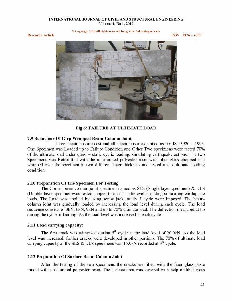
2.8 Mode of Failure The corner Beam Column Joint test specimen was tested under cyclic loading. During the
forward loading cracks have been developed at the top of the specimen. As the loading was progressed the width of crack has been widened. And the reversal of load specimen has to be in the reversed positions, cracks have been formed at the bottom tension and the cracks already formed in the tension face have to be closed. This opening and closing of the cracks has been confirmed till the final failure of the specimen takes place. The complete failure pattern of the BeamColumn Joint is shown in fig.6
INTERNATIONAL JOURNAL OF CIVIL AND STRUCTURAL ENGINEERING Volume 1, No 1, 2010
© Copyright 2010 All rights reserved Integrated Publishing services Research Article ISSN 0976 – 4399
41
Fig 6: FAILURE AT ULTIMATE LOAD
2.9 Behaviour Of Gfrp Wrapped BeamColumn Joint Three specimens are cast and all specimens are detailed as per IS 13920 – 1993.
One Specimen was Loaded up to Failure Condition and Other Two specimens were tested 70% of the ultimate load under quasi – static cyclic loading, simulating earthquake actions. The two Specimens was Retrofitted with the unsaturated polyester resin with fiber glass chopped mat wrapped over the specimen in two different layer thickness and tested up to ultimate loading condition.
2.10 Preparation Of The Specimen For Testing The Corner beam column joint specimen named as SLS (Single layer specimen) & DLS
(Double layer specimen)was tested subject to quasi static cyclic loading simulating earthquake loads. The Load was applied by using screw jack totally 3 cycle were imposed. The beam column joint was gradually loaded by increasing the load level during each cycle. The load sequence consists of 3kN, 6kN, 9kN and up to 70% ultimate load. The deflection measured at tip during the cycle of loading. As the load level was increased in each cycle.
2.11 Load carrying capacity:
The first crack was witnessed during 5 th cycle at the load level of 20.0kN. As the load level was increased, further cracks were developed in other portions. The 70% of ultimate load carrying capacity of the SLS & DLS specimens was 15.0kN recorded at 3 rd cycle.
2.12 Preparation Of Surface Beam Column Joint
After the testing of the two specimens the cracks are filled with the fiber glass paste mixed with unsaturated polyester resin. The surface area was covered with help of fiber glass

INTERNATIONAL JOURNAL OF CIVIL AND STRUCTURAL ENGINEERING Volume 1, No 1, 2010
© Copyright 2010 All rights reserved Integrated Publishing services Research Article ISSN 0976 – 4399
42
paste in all direction as shown in Fig 6.1. The Spalling of the concrete portion are filled with this paste.
Fig No. 7 APPLICATION OF FIBER GLASS PASTE TO THE SPECIMEN
2.13 Wrapping of GFRP Mat With Resin
Glass fiber mat classE grade 300 (chopped Fiber) was used to wrapping the specimens the mat are cut into desired shape. The Unsaturated Polyester resin with accelerator of Cobalt 6% and catalyst of .01% was added with resin mix thoroughly. The Fiber glass mat placed over the specimen and the resin was applied uniformly in all direction with help of brush. Single Layer thickness was applied to the specimen of SLS; Double Layer Thickness was applied to the Specimen of DLS. The specimens are allowed to dry in the room temperature up to 16 Hr.

INTERNATIONAL JOURNAL OF CIVIL AND STRUCTURAL ENGINEERING Volume 1, No 1, 2010
© Copyright 2010 All rights reserved Integrated Publishing services Research Article ISSN 0976 – 4399
43
Fig No. 8 FIBER WRAPPED RC CORNER BEAM COLUMN JOINT
3 Experimental setup:
Each specimen was tested under forward and reverse cyclic loading in the structural laboratory. The column of the test assembly was placed in a loading frame. The column was centered accurately using plumb bob to avoid eccentricity. The bottom end was placed in the frictionless surface. In top of column mild steel plate over 50 tones hydraulic jack was fixed. It’s used for applying axial load for column and also avoids the movement of column. LVDT is used to measure the downward and upward displacements in the beam at a distance of 450mm from the clear face of column. The LVDT was connected to its stand that was in turn connected to the loading frame available in the laboratory.
Fig No. 9 Test Setup (Downward Loading Position)
Fig No. 10 Test Setup (Upward Loading Position)

INTERNATIONAL JOURNAL OF CIVIL AND STRUCTURAL ENGINEERING Volume 1, No 1, 2010
© Copyright 2010 All rights reserved Integrated Publishing services Research Article ISSN 0976 – 4399
44
Fig No. 11 Load Deflection Diagram (SLS&DLS)
3.1 Relative and cumulative energy absorption capacity:
When the beamcolumn joint is subjected to reverse cyclic loading, such as those experienced during heavy wind or earthquake, some energy is absorbed in each load cycle. It is equal to the work in straining or deforming the structure to the limit of deflection. The relative energy absorption capacities during various load cycles were calculated as the sum of the areas under the hysteric loops from the versus loaddeflection diagram.
Fig No. 12 Variation of Cumulative Energy Absorption Capacity for Forward cycles
(SLS&DLS)

INTERNATIONAL JOURNAL OF CIVIL AND STRUCTURAL ENGINEERING Volume 1, No 1, 2010
© Copyright 2010 All rights reserved Integrated Publishing services Research Article ISSN 0976 – 4399
45
Fig No. 13 Variation of Cumulative Energy Absorption Capacity for Backward cycles
(SLS&DLS)
3.2 Ductility Factor and Cumulative Ductility Factor When a structure is subjected to reverse cyclic loading cumulative ductility up to
any load point is defined as the sum of the ductility at maximum load level attained in each cycles up to the cycle considered. This is an important parameter to be considered for earthquake resistant feature of a structure. The cumulative ductility values were found for various cycles are also presented. The cumulative ductility was found to increase from 1.06 for forward and 0.51 for backward during the first cycle to 28 forward and 21.7 for backward during 7 th cycle of loading.
Fig No. 14 Variation of Cumulative Ductility for Forward cycles (SLS&DLS)

INTERNATIONAL JOURNAL OF CIVIL AND STRUCTURAL ENGINEERING Volume 1, No 1, 2010
© Copyright 2010 All rights reserved Integrated Publishing services Research Article ISSN 0976 – 4399
46
Fig No. 15 Variation of Cumulative Ductility for Backward cycles (SLS&DLS)
3.3 Mode of Failure The beamcolumn joint was subjected to 7 cycles to expose the behavior of the beam
column joint. The failure pattern of GFRP beamcolumn joint is shown in fig 16 a &b. As the load increases the crack width is also increased. The concrete was crushed and spalling down.
Fig. 16.a Failure of GFRP wrapped BeamColumn Joint (SLS)

INTERNATIONAL JOURNAL OF CIVIL AND STRUCTURAL ENGINEERING Volume 1, No 1, 2010
© Copyright 2010 All rights reserved Integrated Publishing services Research Article ISSN 0976 – 4399
47
Fig16.b Failure of GFRP wrapped BeamColumn Joint (DLS)
3.4 Comparsion of Test Result The ultimate load carrying capacities of Control and SLS & DLS beamcolumn joints are
shown in the fig 17.From the results it is found that SLS&DLS both joints are having nearly the same load carrying capacity after retrofitting and control specimen having less load carrying capacity.
Fig.17.Comparison of Ultimate Load Carrying Capacity of RC and GFRP Wrapped beam
column joint
3.5 Cumulative Ductility Factor Characteristics
Fig 18 shows the ductility factor of Control and GFRP beamColumn Joint under
reverse cyclic loading.

INTERNATIONAL JOURNAL OF CIVIL AND STRUCTURAL ENGINEERING Volume 1, No 1, 2010
© Copyright 2010 All rights reserved Integrated Publishing services Research Article ISSN 0976 – 4399
48
Fig.18. Comparison of Cumulative Ductility factor of Control and GFRP
Wrapped Beamcolumn Joint (Forward Cycles & Backward cycles)
3.6 Cumulative energy absorption capacity of beams:
The Cumulative Energy Absorption Capacity of the Control and GFRP wrapped beam
column joint is plotted as in the fig.19.
4 Conclusion
Beam column joint in the moment resisting frame have traditionally beam neglected in design process while the individual connected elements, that is, beam and column, have received

INTERNATIONAL JOURNAL OF CIVIL AND STRUCTURAL ENGINEERING Volume 1, No 1, 2010
© Copyright 2010 All rights reserved Integrated Publishing services Research Article ISSN 0976 – 4399
49
considerable attention in design. Research on beam column joint of reinforced concrete moment resisting frame was started only in the 1970s. The 1993 version of IS 13920 – 1993 incorporated some provision on the design of beam column joints. However, the Provisions are inadequate to prevents shear and bond failure of beam column joint in severe seismic shaking. Therefore, these provisions need to be upgraded substantially with inclusion of explicit provisions on shear design and anchorage requirement. This article proposes provision for shear design of beam column joint and anchorage requirements of tension beam bars in the joint area. It also suggests provisions for the confinement of wide beam and column connections. The plastic hinge formation at the joint after the ultimate load.
ü The structural behavior of RCC beam column joint Corner type has been studied . ü Experimental investigation has been carried out and the test results show that the
structural behavior of Corner beam column joint model. ü From test results, important parameters have been worked out such as ductility, energy
absorption etc., in order to assess the seismic behavior of the beam column joint when earthquake comes.
5 Reference
1. ACIASCE Committee 352,”Recommendations for Design of BeamColumn Joints in Monolithic Reinforced Concrete Structures”, American Concrete Institute,1976
2. American Concrete Institute ACI 31889,”Building code Requirements for Reinforced Concrete(ACI31889) American Concrete Institute ,Detroit,1989,351pp
3. A.G.Tsonos, I.A.Tegos and G.Gr.Penelis “Seismic resistance of Type 2 Exterior Beam column joints reinforced with inclined bars” The ACI structural Journal, Title No.89 S1, JanFeb 1992.
4. HungJen Lee and SiYing Yu “Cyclic Response of Exterior BeamColumn Joints with Different Anchorage Methods” The ACI structural Journal, Title No.106S32, May June 2009.