improvement of seismic capacity of external beam-column ... · external beam-column joints using...
TRANSCRIPT
Improvement of seismic capacity of external beam-column joints using rectangular spiral shear reinforcement
C. Karayannis1, G. Sirkelis1 & P. Mavroeidis2
1Department of Civil Engineering, Democritus University of Thrace, Greece 2Metallurgical Engineering
Abstract
In this study the behavior of the external RC beam – column joints with continuous rectangular spiral reinforcement as shear reinforcement in the joint body is experimentally examined. The results of eight specimens are presented. The specimens are sorted into two groups based on the size of the column. The first group (Group A) comprises five specimens with a column cross-section equal to 20/20 cm; one specimen without shear reinforcement in the joint body, two with stirrups and two with rectangular spiral reinforcement as shear reinforcement of the joint. The second group (Group B) comprises three specimens; one without shear reinforcement in the joint body, one with one stirrup in the joint body and one with rectangular spiral reinforcement in the joint body. All specimens have suffered the same loading with increasing deformation and two full cycles at every step. Maximum displacements of the beam's free end in the loading cycles were ±6mm, ±20mm, ±40mm, ±60mm and ±80 mm for the 1st, 2nd, 3rd, 4th and 5th loading step, respectively. The results from the specimens reinforced with rectangular spiral reinforcement are compared with the results from the specimens reinforced with stirrups, in terms of maximum loading and energy absorption per step, and ductility capacity. From the observed responses of the tested specimens it can be deduced that the use of rectangular spiral reinforcement in the joint body significantly improved the seismic capacity of the examined external beam-column connections. Keywords: beam-column joints, spiral shear reinforcement.
© 2005 WIT Press WIT Transactions on The Built Environment, Vol 81, www.witpress.com, ISSN 1743-3509 (on-line)
Earthquake Resistant Engineering Structures V 147
1 Introduction
It is generally accepted that the use of continuous spiral reinforcement in reinforced concrete elements with cyclic cross section can substantial improve the strength and the ductility of the concrete and henceforth the total seismic response and capacity of the structural element (Park and Paulay [7], Saatcioglu and Razvi [9], Sheikh and Toklucu [10]). International codes in these cases propose increased performance factors for the concrete confinement (ACI 318, EC8). The extension of the use of continuous spiral reinforcement in elements with rectangular cross sections is a new promising technology that is believed it can improve the seismic capacity of structures. It is generally acceptable that the beam-column joints and especially the external joints are critical regions for the total seismic response of reinforced concrete structures. Thus, any improvement of the seismic properties of these areas using the Rectangular Spiral Reinforcement (RSR) would be very interesting in terms of reinforcing strategy and structural safety. The response of beam – column joints depends on quite a few different factors as the mechanisms of shear transfer, the concrete compressive and shear strengths, the confinement of the joint area, the anchorage type of the beam’s longitudinal reinforcement etc (Paulay and Priestley [8], Karayannis et al. [2], Karayannis and Sirkelis [3,5]). It is obvious that the improvement of the concrete response in terms of any of these factors would help to the improvement of the total seismic response of the joint. Considering that the application of the RSR could contribute to the improvement of the concrete properties it is expected to contribute to the total improvement of the response of the joints. The scope of this study is the experimental investigation of the possibility of the improvement of seismic capacity of external beam – column joints using continuous rectangular spiral shear reinforcement in the column and in the joint area. The results from the specimens reinforced with spiral reinforcement are compared with the results from specimens reinforced with stirrups, in terms of hysteretic response, ductility and energy absorption.
2 Experimental program
The experimental program comprises eight specimens of external beam-column joints. The specimens are sorted into two groups based on the size of the column. The characteristics of all specimens are presented in Table 1.
The geometric characteristics of the specimens of Group A were the same for all specimens. The total column length was 180 cm and the column cross-section was 20×20 cm. The column reinforcement was 4∅10. The total beam length was 110 cm and the beam cross-section was 20/30 cm. The beam reinforcement was 4∅10 (2∅10 up, 2∅10 down). The beam’s reinforcement anchorage for specimens of Group A has the recommended by the code total length, but the
© 2005 WIT Press WIT Transactions on The Built Environment, Vol 81, www.witpress.com, ISSN 1743-3509 (on-line)
148 Earthquake Resistant Engineering Structures V
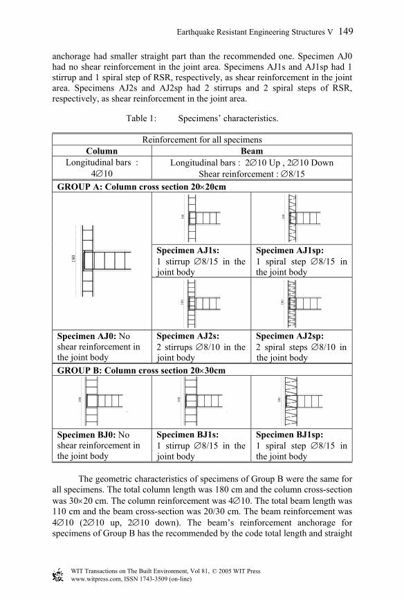
anchorage had smaller straight part than the recommended one. Specimen AJ0 had no shear reinforcement in the joint area. Specimens AJ1s and AJ1sp had 1 stirrup and 1 spiral step of RSR, respectively, as shear reinforcement in the joint area. Specimens AJ2s and AJ2sp had 2 stirrups and 2 spiral steps of RSR, respectively, as shear reinforcement in the joint area.
Table 1: Specimens’ characteristics.
Reinforcement for all specimens Column Beam
Longitudinal bars : 4∅10
Longitudinal bars : 2∅10 Up , 2∅10 Down Shear reinforcement : ∅8/15
GROUP A: Column cross section 20×20cm 18
0
180
Specimen AJ1s: 1 stirrup ∅8/15 in the joint body
Specimen AJ1sp: 1 spiral step ∅8/15 in the joint body
180
180
180
Specimen AJ0: No shear reinforcement in the joint body
Specimen AJ2s: 2 stirrups ∅8/10 in the joint body
Specimen AJ2sp: 2 spiral steps ∅8/10 in the joint body
GROUP B: Column cross section 20×30cm
180
180
180
Specimen BJ0: No shear reinforcement in the joint body
Specimen BJ1s: 1 stirrup ∅8/15 in the joint body
Specimen BJ1sp: 1 spiral step ∅8/15 in the joint body
The geometric characteristics of specimens of Group B were the same for all specimens. The total column length was 180 cm and the column cross-section was 30×20 cm. The column reinforcement was 4∅10. The total beam length was 110 cm and the beam cross-section was 20/30 cm. The beam reinforcement was 4∅10 (2∅10 up, 2∅10 down). The beam’s reinforcement anchorage for specimens of Group B has the recommended by the code total length and straight
© 2005 WIT Press WIT Transactions on The Built Environment, Vol 81, www.witpress.com, ISSN 1743-3509 (on-line)
Earthquake Resistant Engineering Structures V 149
part. Specimen BJ0 had no shear reinforcement in the joint area. Specimens BJ1s and BJ1sp had 1 stirrup and 1 spiral step of RSR, respectively, as shear reinforcement in the joint area. The concrete mean compressive strength for all specimens was fc=32,8 MPa. Column axial load Nc = 70 kN was applied during the test in all specimens.
2.1 Test ring and loading procedure
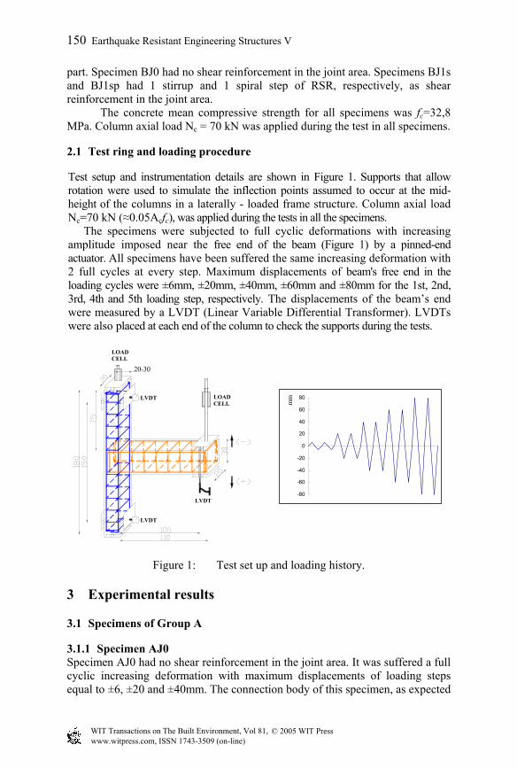
Test setup and instrumentation details are shown in Figure 1. Supports that allow rotation were used to simulate the inflection points assumed to occur at the mid-height of the columns in a laterally - loaded frame structure. Column axial load Nc=70 kN (≈0.05Acfc), was applied during the tests in all the specimens.
The specimens were subjected to full cyclic deformations with increasing amplitude imposed near the free end of the beam (Figure 1) by a pinned-end actuator. All specimens have been suffered the same increasing deformation with 2 full cycles at every step. Maximum displacements of beam's free end in the loading cycles were ±6mm, ±20mm, ±40mm, ±60mm and ±80mm for the 1st, 2nd, 3rd, 4th and 5th loading step, respectively. The displacements of the beam’s end were measured by a LVDT (Linear Variable Differential Transformer). LVDTs were also placed at each end of the column to check the supports during the tests.
20-30
LOAD CELL
LOAD CELL
LVDT
LVDT
LVDT
-80
-60
-40
-20
0
20
40
60
80
mm
Figure 1: Test set up and loading history.
3 Experimental results
3.1 Specimens of Group A
3.1.1 Specimen AJ0 Specimen AJ0 had no shear reinforcement in the joint area. It was suffered a full cyclic increasing deformation with maximum displacements of loading steps equal to ±6, ±20 and ±40mm. The connection body of this specimen, as expected
© 2005 WIT Press WIT Transactions on The Built Environment, Vol 81, www.witpress.com, ISSN 1743-3509 (on-line)
150 Earthquake Resistant Engineering Structures V
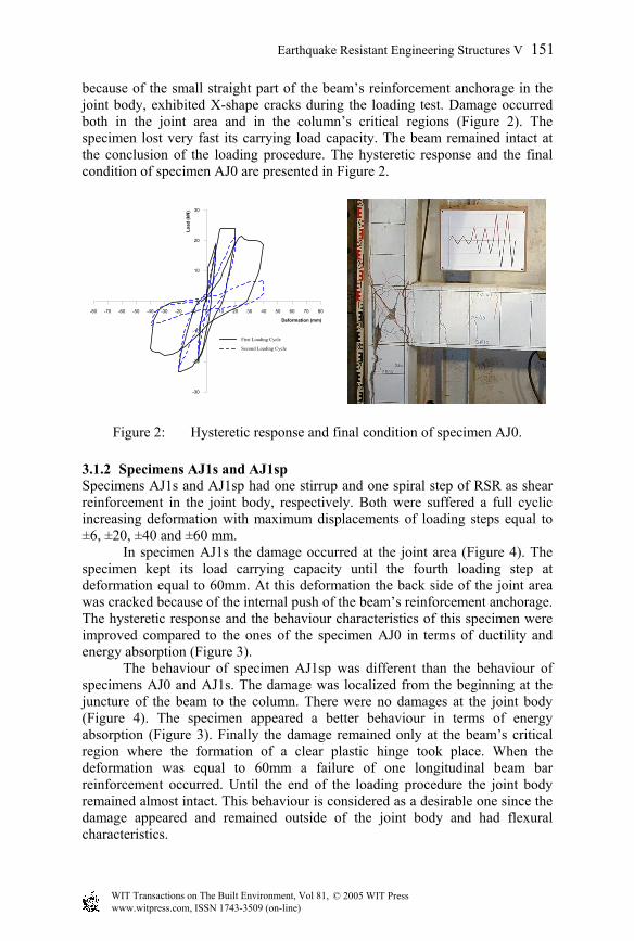
because of the small straight part of the beam’s reinforcement anchorage in the joint body, exhibited X-shape cracks during the loading test. Damage occurred both in the joint area and in the column’s critical regions (Figure 2). The specimen lost very fast its carrying load capacity. The beam remained intact at the conclusion of the loading procedure. The hysteretic response and the final condition of specimen AJ0 are presented in Figure 2.
-80 -70 -60 -50 -40 -30 -20 -10 0 10 20 30 40 50 60 70 80
Deformation (mm)
-30
-20
-10
0
10
20
30
Load
(kN
)
First Loading Cycle
Second Loading Cycle
Figure 2: Hysteretic response and final condition of specimen AJ0.
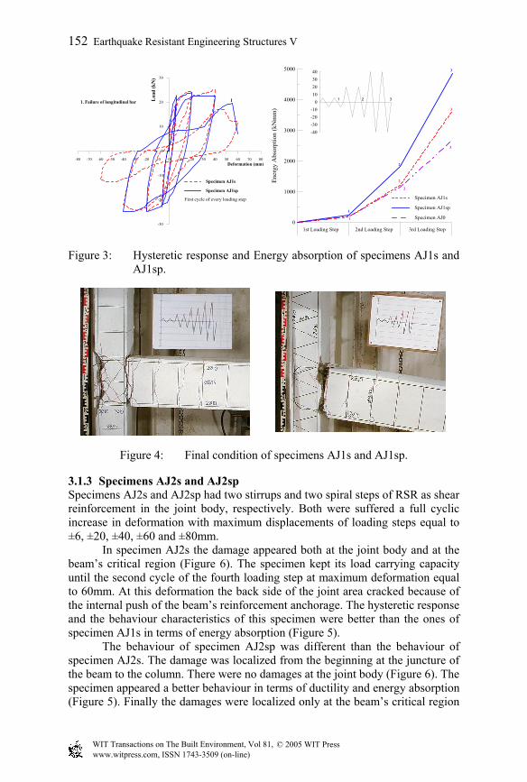
3.1.2 Specimens AJ1s and AJ1sp Specimens AJ1s and AJ1sp had one stirrup and one spiral step of RSR as shear reinforcement in the joint body, respectively. Both were suffered a full cyclic increasing deformation with maximum displacements of loading steps equal to ±6, ±20, ±40 and ±60 mm. In specimen AJ1s the damage occurred at the joint area (Figure 4). The specimen kept its load carrying capacity until the fourth loading step at deformation equal to 60mm. At this deformation the back side of the joint area was cracked because of the internal push of the beam’s reinforcement anchorage. The hysteretic response and the behaviour characteristics of this specimen were improved compared to the ones of the specimen AJ0 in terms of ductility and energy absorption (Figure 3). The behaviour of specimen AJ1sp was different than the behaviour of specimens AJ0 and AJ1s. The damage was localized from the beginning at the juncture of the beam to the column. There were no damages at the joint body (Figure 4). The specimen appeared a better behaviour in terms of energy absorption (Figure 3). Finally the damage remained only at the beam’s critical region where the formation of a clear plastic hinge took place. When the deformation was equal to 60mm a failure of one longitudinal beam bar reinforcement occurred. Until the end of the loading procedure the joint body remained almost intact. This behaviour is considered as a desirable one since the damage appeared and remained outside of the joint body and had flexural characteristics.
© 2005 WIT Press WIT Transactions on The Built Environment, Vol 81, www.witpress.com, ISSN 1743-3509 (on-line)
Earthquake Resistant Engineering Structures V 151
-80 -70 -60 -50 -40 -30 -20 -10 0 10 20 30 40 50 60 70 80Deformation (mm)
-30
-20
-10
0
10
20
30
Load
(kN
)
Specimen AJ1s
Specimen AJ1sp
First cycle of every loading step
11. Failure of longitudinal bar
0
1000
2000
3000
4000
5000
Ener
gy A
bsor
ptio
n (k
Nm
m)
1st Loading Step 3rd Loading Step
Specimen AJ1s
Specimen AJ1sp
Specimen AJ0
-40-30-20-10
010203040
1 2 3
1
2
3
1
2
3
2nd Loading Step
2
3
Figure 3: Hysteretic response and Energy absorption of specimens AJ1s and AJ1sp.
Figure 4: Final condition of specimens AJ1s and AJ1sp.
3.1.3 Specimens AJ2s and AJ2sp Specimens AJ2s and AJ2sp had two stirrups and two spiral steps of RSR as shear reinforcement in the joint body, respectively. Both were suffered a full cyclic increase in deformation with maximum displacements of loading steps equal to ±6, ±20, ±40, ±60 and ±80mm. In specimen AJ2s the damage appeared both at the joint body and at the beam’s critical region (Figure 6). The specimen kept its load carrying capacity until the second cycle of the fourth loading step at maximum deformation equal to 60mm. At this deformation the back side of the joint area cracked because of the internal push of the beam’s reinforcement anchorage. The hysteretic response and the behaviour characteristics of this specimen were better than the ones of specimen AJ1s in terms of energy absorption (Figure 5). The behaviour of specimen AJ2sp was different than the behaviour of specimen AJ2s. The damage was localized from the beginning at the juncture of the beam to the column. There were no damages at the joint body (Figure 6). The specimen appeared a better behaviour in terms of ductility and energy absorption (Figure 5). Finally the damages were localized only at the beam’s critical region
© 2005 WIT Press WIT Transactions on The Built Environment, Vol 81, www.witpress.com, ISSN 1743-3509 (on-line)
152 Earthquake Resistant Engineering Structures V
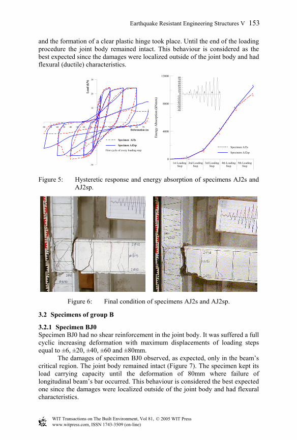
and the formation of a clear plastic hinge took place. Until the end of the loading procedure the joint body remained intact. This behaviour is considered as the best expected since the damages were localized outside of the joint body and had flexural (ductile) characteristics.
-80 -70 -60 -50 -40 -30 -20 -10 0 10 20 30 40 50 60 70Deformation (m
-30
-20
-10
0
10
20
30
Load
(kN
)
Specimen AJ2s
Specimen AJ2sp
First cycle of every loading step
0
4000
8000
12000
Ener
gy A
bsor
ptio
n (k
Nm
m)
1st Loading Step
3rd LoadingStep
Specimen AJ2s
Specimen AJ2sp
-80-70-60-50-40-30-20-10
01020304050607080
1 2 3
1
2
3
1
2
2nd LoadingStep
4th LoadingStep
4
3
44
5
5th LoadingStep
5
5
Figure 5: Hysteretic response and energy absorption of specimens AJ2s and AJ2sp.
Figure 6: Final condition of specimens AJ2s and AJ2sp.
3.2 Specimens of group B
3.2.1 Specimen BJ0 Specimen BJ0 had no shear reinforcement in the joint body. It was suffered a full cyclic increasing deformation with maximum displacements of loading steps equal to ±6, ±20, ±40, ±60 and ±80mm. The damages of specimen BJ0 observed, as expected, only in the beam’s critical region. The joint body remained intact (Figure 7). The specimen kept its load carrying capacity until the deformation of 80mm where failure of longitudinal beam’s bar occurred. This behaviour is considered the best expected one since the damages were localized outside of the joint body and had flexural characteristics.
© 2005 WIT Press WIT Transactions on The Built Environment, Vol 81, www.witpress.com, ISSN 1743-3509 (on-line)
Earthquake Resistant Engineering Structures V 153
-80 -70 -60 -50 -40 -30 -20 -10 0 10 20 30 40 50 60 70 80Deformation (mm)
-30
-20
-10
0
10
20
30
Load
(kN
)
First loading cycle
Second loading cycle1
1. Failure of longitudinal bar
Figure 7: Hysteretic response and final condition of specimen BJ0.
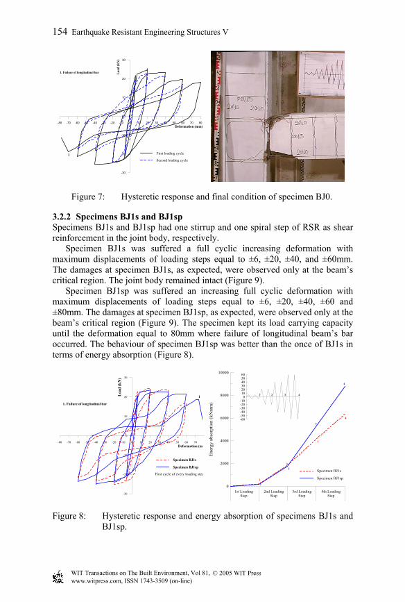
3.2.2 Specimens BJ1s and BJ1sp Specimens BJ1s and BJ1sp had one stirrup and one spiral step of RSR as shear reinforcement in the joint body, respectively.
Specimen BJ1s was suffered a full cyclic increasing deformation with maximum displacements of loading steps equal to ±6, ±20, ±40, and ±60mm. The damages at specimen BJ1s, as expected, were observed only at the beam’s critical region. The joint body remained intact (Figure 9).
Specimen BJ1sp was suffered an increasing full cyclic deformation with maximum displacements of loading steps equal to ±6, ±20, ±40, ±60 and ±80mm. The damages at specimen BJ1sp, as expected, were observed only at the beam’s critical region (Figure 9). The specimen kept its load carrying capacity until the deformation equal to 80mm where failure of longitudinal beam’s bar occurred. The behaviour of specimen BJ1sp was better than the once of BJ1s in terms of energy absorption (Figure 8).
-80 -70 -60 -50 -40 -30 -20 -10 0 10 20 30 40 50 60 70Deformation (m
-30
-20
-10
0
10
20
30
Load
(kN
)
Specimen BJ1s
Specimen BJ1sp
First cycle of every loading step
1
1. Failure of longitudinal bar
0
2000
4000
6000
8000
10000
Ener
gy a
bsor
ptio
n (k
Nm
m)
1st LoadingStep
3rd LoadingStep
Specimen BJ1s
Specimen BJ1sp
-60-50-40-30-20-10
0102030405060
1 2 3
1
2
3
1
2
2nd LoadingStep
4th LoadingStep
4
3
4
4
Figure 8: Hysteretic response and energy absorption of specimens BJ1s and BJ1sp.
© 2005 WIT Press WIT Transactions on The Built Environment, Vol 81, www.witpress.com, ISSN 1743-3509 (on-line)
154 Earthquake Resistant Engineering Structures V
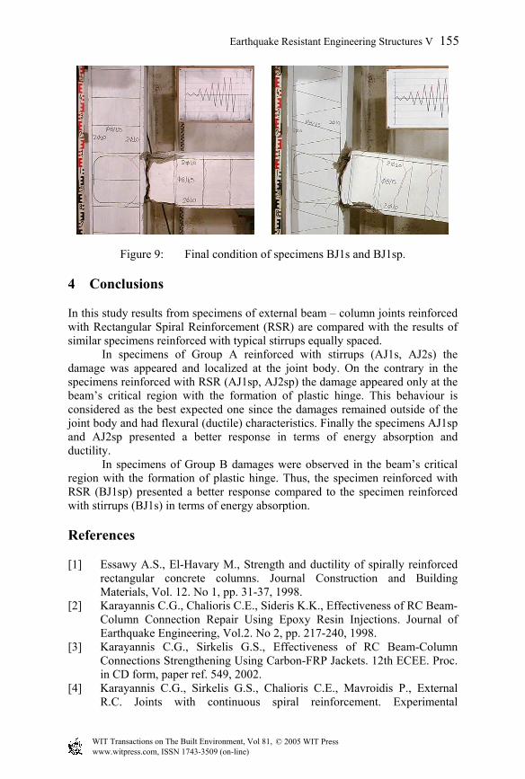
Figure 9: Final condition of specimens BJ1s and BJ1sp.
4 Conclusions
In this study results from specimens of external beam – column joints reinforced with Rectangular Spiral Reinforcement (RSR) are compared with the results of similar specimens reinforced with typical stirrups equally spaced. In specimens of Group A reinforced with stirrups (AJ1s, AJ2s) the damage was appeared and localized at the joint body. On the contrary in the specimens reinforced with RSR (AJ1sp, AJ2sp) the damage appeared only at the beam’s critical region with the formation of plastic hinge. This behaviour is considered as the best expected one since the damages remained outside of the joint body and had flexural (ductile) characteristics. Finally the specimens AJ1sp and AJ2sp presented a better response in terms of energy absorption and ductility. In specimens of Group B damages were observed in the beam’s critical region with the formation of plastic hinge. Thus, the specimen reinforced with RSR (BJ1sp) presented a better response compared to the specimen reinforced with stirrups (BJ1s) in terms of energy absorption.
References
[1] Essawy A.S., El-Havary M., Strength and ductility of spirally reinforced rectangular concrete columns. Journal Construction and Building Materials, Vol. 12. No 1, pp. 31-37, 1998.
[2] Karayannis C.G., Chalioris C.E., Sideris K.K., Effectiveness of RC Beam-Column Connection Repair Using Epoxy Resin Injections. Journal of Earthquake Engineering, Vol.2. No 2, pp. 217-240, 1998.
[3] Karayannis C.G., Sirkelis G.S., Effectiveness of RC Beam-Column Connections Strengthening Using Carbon-FRP Jackets. 12th ECEE. Proc. in CD form, paper ref. 549, 2002.
[4] Karayannis C.G., Sirkelis G.S., Chalioris C.E., Mavroidis P., External R.C. Joints with continuous spiral reinforcement. Experimental
© 2005 WIT Press WIT Transactions on The Built Environment, Vol 81, www.witpress.com, ISSN 1743-3509 (on-line)
Earthquake Resistant Engineering Structures V 155
investigation. 14th Greek Concrete Conference, Vol. A, pp. 343-353, In Greek, 2003.
[5] Karayannis C.G., Sirkelis G.S., Design parameters and response of external joints-Damage index and valuation of experimental results. 14th Greek Concrete Conference, Vol. A, pp. 332-342, In Greek, 2003.
[6] Karayannis C.G., Sirkelis G.S., Chalioris C.E., Εffectiveness of RC Beam-Column Connections Strengthening Using Carbon-FRP Jackets. 12th European Conference on Earthquake Engineering (12ECEE), Paper Ref.549, 2003.
[7] Park R., Paulay T., Reinforced Concrete Structures. John Wiley & Sons. 1975.
[8] Paulay T., Priestley M.J.N., Seismic design of reinforced concrete and masonry buildings. John Wiley & Sons, 1992.
[9] Saatcioglu M., Razvi S., Strength and ductility of confined concrete. Journal of Structural Engineering ASCE, Vol. 118, No 25, pp. 1590-1607, 1992.
[10] Sheik S., Toclucu M., Reinforced concrete columns confined by circular spirals and hoops. ACI Structural Journal, Vol. 90, No 5, pp. 542-553, 1993.
© 2005 WIT Press WIT Transactions on The Built Environment, Vol 81, www.witpress.com, ISSN 1743-3509 (on-line)
156 Earthquake Resistant Engineering Structures V