investigation of soil-sweep interaction in laboratory soil ...€¦ · investigation of soil-sweep...
TRANSCRIPT
Investigation of soil-sweep interaction in laboratory soil bin and modelling
with discrete element method
Kornél Tamás, Zsófia Oláh, Lilla Rácz-Szabó
Budapest University of Technology and
Economics
Department of Machine and Product Design
H-1111 Budapest, Műegyetem rkp. 3.
MG building 300.
Zoltán Hudoba
NARIC Institute of Agricultural Engineering Gödöllő, H-2100, Tessedik Sámuel u. 4
KEYWORDS
Soil-sweep interaction, Soil bin, DEM, Clumps
ABSTRACT
Nowadays, it is important to preserve the
moisture content of the soil which can be executed
with cultivator tools. The objective of this study was
the investigation of the energetic and working
quality characteristics of sweep tools by soil bin
experiments conducted in laboratory conditions and
the simultaneous development of a discrete element
model (DEM) validated by comparing the measured
and the simulated values of draught forces. Three
sweeps were analyzed differing in aspects of shape
and size; the tool widths were 100, 230 and 300 mm,
respectively. Experiments were conducted in the
NARIC Institute of Agricultural Engineering soil bin
facility filled with sandy soil with volumetric
moisture content of 2% and 15%, at three different
working speeds (0.5, 1, 2 m/s) at the working depth
of 0.15 m. The improved DEM model contain a soil
model consisting of discrete particles created within
the Yade software and 3D laser scanned model of the
sweep tools. Inserting the analyzed tool geometry
into the simulation made it possible to investigate the
characteristics of the tillage tools and also the effect
of the different geometries appearing in the soil
cutting forces. The investigation of the effect of the
shape of the particles on the energy dissipation and
studying the differences between the validated
frictional and the cohesive soil models based on the
soil bin test were the aim within this study.
INTRODUCTION
Agriculture is an important part of our daily
life and supplies food to the world's population.
Therefore, appropriate soil conditions must be
ensured for the crops grown. In order to increase
productivity, there are several possibilities to
influence the processes in the soil using different
mechanical methods. One of the appropriate tools for
this is the sweep tool that does not mix the soil, so
the moisture content in the affected soil layer is not
exposed to the surface and the soil does not dry out.
This is especially important, because the aim of the
loosening process with a sweep tool is the seedbed
preparation, cutting plants’ roots beside the
reduction of moisture loss of the cultivated soil.
The development of computer technology
put thorough investigation of soil-tool interaction
within reach and made it possible to study certain
areas of soil mechanics and analyze results which are
difficult to achieve in experiments or solely with
analytical methods, considering the complexity of
the matter. Among the numerical methods, the FEM
(finite element method) spread initially: both two-
and three-dimensional models were developed. As
the computing capacity increased, the calculation
time was reduced, enabling the appearance of more
complex numerical simulations such as the CFD
(computational fluid dynamics), which is a proper
technique to investigate the soil movement from a
flow point perspective and the SPH (smooth particle
hydrodynamics) method, which is suitable to
analyze the soil loosening processes (Urbán et al.
2012; Zachár et al. 2016).
Nevertheless, it is difficult to use the FEM
or the aforementioned other methods when
researchers encounter problems in which the discrete
nature of the particles of the material is crucial. In
the case of these problematic areas, where the
discrete nature of the granulated material is key, the
DEM (discrete element method) can be a proper
technique to use (Bagi 2007; Tamás 2016).
Proceedings 32nd European Conference on Modelling and Simulation ©ECMS Lars Nolle, Alexandra Burger, Christoph Tholen, Jens Werner, Jens Wellhausen (Editors) ISBN: 978-0-9932440-6-3/ ISBN: 978-0-9932440-7-0 (CD)
Initially, researchers mainly investigated
the behavior of spherical particles, although in
reality granular particles are generally non-spherical,
therefore the utilization of particles with a more
complex shape was needed. The internal structure of
the granular material is transformed by the particles
rolling down and interlocking, and thus the behavior
of the set is greatly influenced by the shape of the
particles, which can also be considered as an input
parameter to be calibrated. Researchers also use
ellipsoids, polyhedrons and clumps as particles. The
shape of the material particles is responsible for the
extent of the energy dissipation in the material set,
so the examination of the effect of the particle shape
has also played an important role in this research.
The previous models of soil-tool interaction
mostly presumed friction in the soil, but because of
its moisture content the soil also shows a cohesive
behavior. By increasing the moisture content, the
draught force is also increasing, so the introduction
of cohesive models was necessary. The focus of this
study was the examination of the soil-tool interaction:
the main aim was to create a three dimensional DEM
model simultaneously with the execution of a
laboratory soil bin experiment. An another aim was
to carry out the calibration process of the DEM
model that was created, with particular emphasis on
finding the most appropriate particle shape regarding
its effect on the extent of energy dissipation of the
interaction. The additional objective was to improve
the micromechanical parameter set used in the DEM
model of soil-sweep tool interaction by comparing
laboratory and simulation results with the use of
relative error method.
THE SOIL BIN TEST
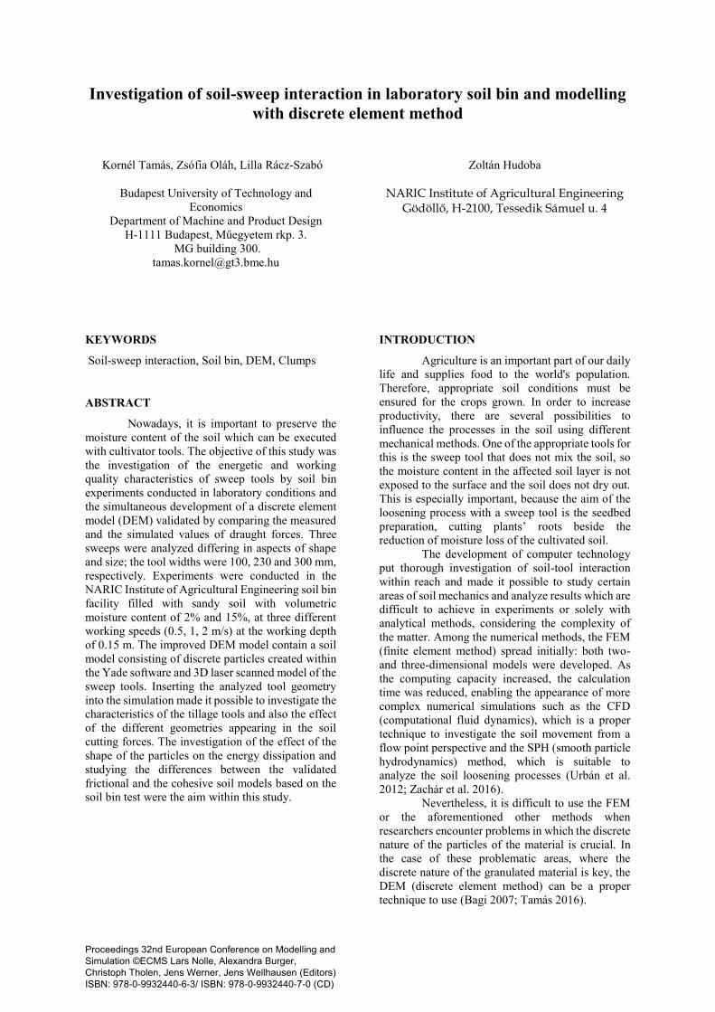
In order to create a DEM model, in the first
step soil bin study was conducted (Figure 1). The
measurements were carried out in the soil bin facility
of NARIC Institute of Agricultural Engineering,
Gödöllő, Hungary. The laboratory soil bin was filled
with sandy soil with the following content: 93% of
sand, 4.66% of silt and 2.06% of clay. The dry bulk
density was calculated by the results of a previously
conducted oedometer test, and was determined as
1424.12 kg/m3. For the investigation of soil-tool
interaction three different sweep geometry were used
with the tool width (W) of 100, 230 and 300 mm,
respectively, henceforward referring to them as
small, medium and large sweep tools (Gürsoy et al.
2017). The experiment focused on the relation
between draught force and working speed. Three
different working speeds were used, in average 0.5,
1, 2 m/s. The soil bin study was made at the tool’s
working depth of 0.15 m.
a,
b,
Primarily the relation between draught
force and working speed was analyzed. Also another
aim of this measurement was to study soil particles’
displacements in a vertical direction, and the effect
of soil moisture content.
Following the proper preparation of the
sandy soil, the penetration resistance and volumetric
moisture content measurements were conducted. In
Figure 1: The soil bin of the NARIC Institute of
Agricultural Engineering a) the sweep tool in the soil
and b) the soil loosening process
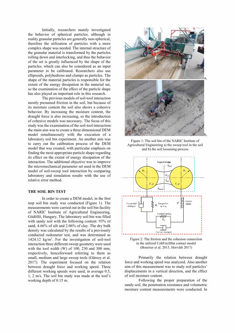
Figure 2: The friction and the cohesion connection
in the utilized CohFrictMat contact model
(Bourrier et al. 2013, Horváth 2017)
case of dry soil, the volumetric moisture content of
2% was observed, and in case of wet soil a value of
15% was measured.
In the case of the dry sandy soil, vertical
penetration resistance was about 1.12 MPa, and in
wet sandy soil it fluctuated around 0.72 MPa. The
initial soil profile was then recorded.
Along the measuring section the draught
force was monitored, the time required to take the
measuring section and the working speed. The sweep,
with a rigid tine, was mounted with supports to the
tool’s draught force with calibrated strain gauges.
The soil profiles formed after the
measurements were also recorded using a laser
scanner. These were suitable for comparison with the
initial soil profile to conclude how the analyzed tool
geometries differ in lifting and mixing the soil at a
given speed and how far the ground is lifted
vertically by them. As the soil particles can only
move upwards during the loosening process
influenced by sweep tools, therefore a volume
increase can be observed in the cultivated layer of
the soil.
GENERAL INFORMATION OF DEM
MODELING
For developing the DEM model, the Yade
open-source software (Šmilauer et al. 2015) was
used, in which several different contact models were
available regarding the mechanical relation between
discrete particles, including FrictMat (frictional) and
CohFrictMat (frictional and cohesive) models
(Figure 2).
The applied software performs a collision
detection to analyze the interactions between the
particles involved in the simulation and uses
timestep, after which all particles can change their
mutual positions. As a first step of the process, the
software sets the forces to default, then updates the
bindings. After that detects the impact and then
calculate the forces based on the displacements. Then speed and position of particles are updated.
Running various motors, recording data, and
increasing the time step are the following steps.
Geometrical model of soil particles
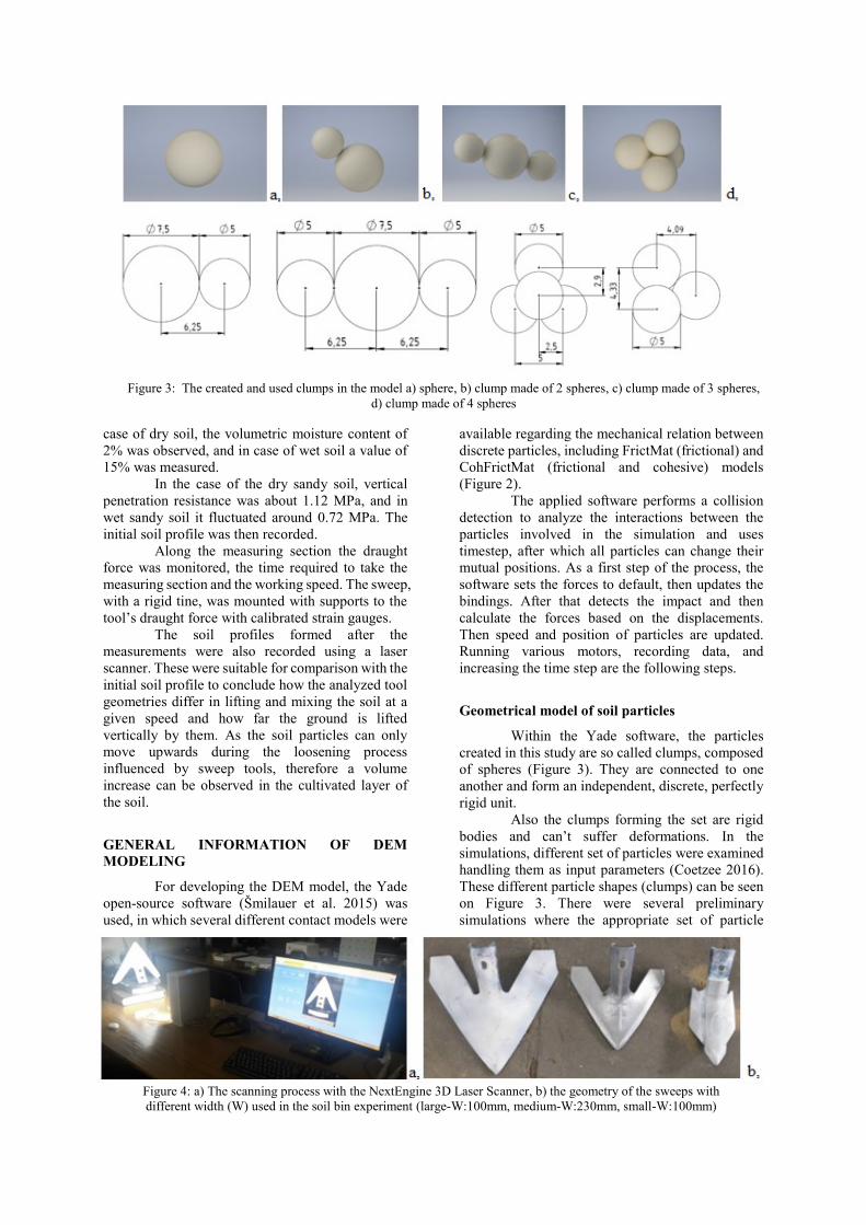
Within the Yade software, the particles
created in this study are so called clumps, composed
of spheres (Figure 3). They are connected to one
another and form an independent, discrete, perfectly
rigid unit.
Also the clumps forming the set are rigid
bodies and can’t suffer deformations. In the
simulations, different set of particles were examined
handling them as input parameters (Coetzee 2016).
These different particle shapes (clumps) can be seen
on Figure 3. There were several preliminary
simulations where the appropriate set of particle
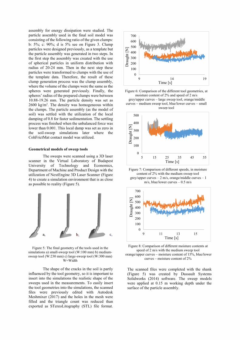
Figure 4: a) The scanning process with the NextEngine 3D Laser Scanner, b) the geometry of the sweeps with
different width (W) used in the soil bin experiment (large-W:100mm, medium-W:230mm, small-W:100mm)
Figure 3: The created and used clumps in the model a) sphere, b) clump made of 2 spheres, c) clump made of 3 spheres,
d) clump made of 4 spheres
assembly for energy dissipation were studied. The
particle assembly used in the final soil model was
consisting of the following ratio of the given clumps:
b: 5%; c: 90%; d is 5% see on Figure 3. Clump
particles were designed previously, as a template but
the particle assembly was generated in two steps. In
the first step the assembly was created with the use
of spherical particles in uniform distribution with
radius of 20-24 mm. Then in the next step these
particles were transformed to clumps with the use of
the template data. Therefore, the result of these
clump generation process was the clump assembly,
where the volume of the clumps were the same as the
spheres were generated previously. Finally, the
spheres’ radius of the prepared clumps were between
10.88-19.26 mm. The particle density was set as
2600 kg/m3. The density was homogeneous within
the clumps. The particle assembly (as the model of
soil) was settled with the utilization of the local
damping of 0.8 for faster sedimentation. The settling
process was finished when the unbalanced force was
lower than 0.001. This local damp was set as zero in
the soil-sweep simulations later where the
CohFrictMat contact model was utilized.
Geometrical models of sweep tools
The sweeps were scanned using a 3D laser
scanner in the Virtual Laboratory of Budapest
University of Technology and Economics,
Department of Machine and Product Design with the
utilization of NextEngine 3D Laser Scanner (Figure
4) to create a simulation environment that is as close
as possible to reality (Figure 5).
The shape of the cracks in the soil is partly
influenced by the tool geometry, so it is important to
insert into the simulations the realistic shape of the
sweeps used in the measurements. To easily insert
the tool geometries into the simulations, the scanned
files were previously edited with Autodesk
Meshmixer (2017) and the holes in the mesh were
filled and the triangle count was reduced than
exported as STereoLitography (STL) file format.
The scanned files were completed with the shank
(Figure 5) was created by Dassault Systems
Solidworks (2014) software. The sweep models
were applied at 0.15 m working depth under the
surface of the particle assembly.
Figure 5: The final geometry of the tools used in the
simulations a) small-sweep tool (W:100 mm) b) medium-
sweep tool (W:230 mm) c) large-sweep tool (W:300 mm)
W=Width
0
100
200
300
400
500
600
700
9 14 19
Dra
ught
[N]
Time [s]
0
100
200
300
400
500
5 15 25 35 45 55
Dra
ught
[N]
Time [s]
0
100
200
300
400
500
600
700
9 11 13 15
Dra
ught
[N]
Time [s]
Figure 6: Comparison of the different tool geometries, at
moisture content of 2% and speed of 2 m/s
grey/upper curves – large sweep tool, orange/middle
curves – medium sweep tool, blue/lower curves – small
sweep tool
Figure 7: Comparison of different speeds, in moisture
content of 2% with the medium sweep tool
grey/upper curves – 2 m/s, orange/middle curves – 1
m/s, blue/lower curves – 0.5 m/s
Figure 8: Comparison of different moisture contents at
speed of 2 m/s with the medium sweep tool
orange/upper curves – moisture content of 15%, blue/lower
curves – moisture content of 2%
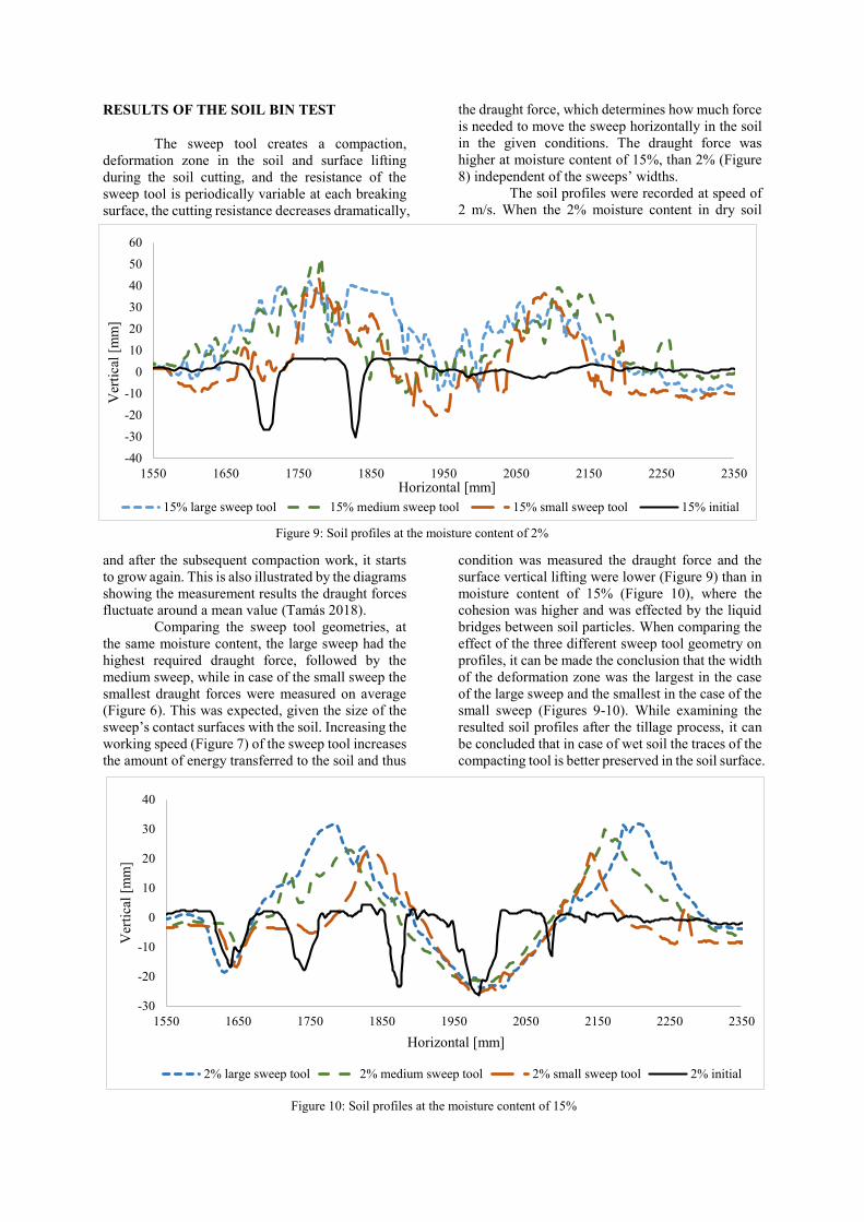
RESULTS OF THE SOIL BIN TEST
The sweep tool creates a compaction,
deformation zone in the soil and surface lifting
during the soil cutting, and the resistance of the
sweep tool is periodically variable at each breaking
surface, the cutting resistance decreases dramatically,
and after the subsequent compaction work, it starts
to grow again. This is also illustrated by the diagrams
showing the measurement results the draught forces
fluctuate around a mean value (Tamás 2018).
Comparing the sweep tool geometries, at
the same moisture content, the large sweep had the
highest required draught force, followed by the
medium sweep, while in case of the small sweep the
smallest draught forces were measured on average
(Figure 6). This was expected, given the size of the
sweep’s contact surfaces with the soil. Increasing the
working speed (Figure 7) of the sweep tool increases
the amount of energy transferred to the soil and thus
the draught force, which determines how much force
is needed to move the sweep horizontally in the soil
in the given conditions. The draught force was
higher at moisture content of 15%, than 2% (Figure
8) independent of the sweeps’ widths.
The soil profiles were recorded at speed of
2 m/s. When the 2% moisture content in dry soil
condition was measured the draught force and the
surface vertical lifting were lower (Figure 9) than in
moisture content of 15% (Figure 10), where the
cohesion was higher and was effected by the liquid
bridges between soil particles. When comparing the
effect of the three different sweep tool geometry on
profiles, it can be made the conclusion that the width
of the deformation zone was the largest in the case
of the large sweep and the smallest in the case of the
small sweep (Figures 9-10). While examining the
resulted soil profiles after the tillage process, it can
be concluded that in case of wet soil the traces of the
compacting tool is better preserved in the soil surface.
-30
-20
-10
0
10
20
30
40
1550 1650 1750 1850 1950 2050 2150 2250 2350
Ver
tica
l [m
m]
Horizontal [mm]
2% large sweep tool 2% medium sweep tool 2% small sweep tool 2% initial
-40
-30
-20
-10
0
10
20
30
40
50
60
1550 1650 1750 1850 1950 2050 2150 2250 2350
Ver
tica
l [m
m]
Horizontal [mm]
15% large sweep tool 15% medium sweep tool 15% small sweep tool 15% initial
Figure 9: Soil profiles at the moisture content of 2%
Figure 10: Soil profiles at the moisture content of 15%
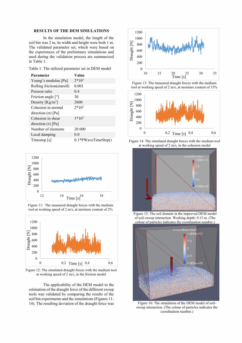
RESULTS OF THE DEM SIMULATIONS
In the simulation model, the length of the
soil bin was 2 m, its width and height were both 1 m.
The validated parameter set, which were based on
the experiences of the preliminary simulations and
used during the validation process are summarized
in Table 1.
Table 1: The utilized parameter set in DEM model
The applicability of the DEM model to the
estimation of the draught force of the different sweep
tools was validated by comparing the results of the
soil bin experiments and the simulations (Figures 11-
14). The resulting deviation of the draught force was
Parameter Value
Young’s modulus [Pa] 2*105
Rolling friction(etaroll) 0.001
Poisson ratio 0.4
Friction angle [°] 30
Density [Kg/m3] 2600
Cohesion in normal
direction (σ) [Pa]
2*103
Cohesion in shear
direction (τ) [Pa]
1*103
Number of elements 20 000
Local damping 0.0
Timestep [s] 0.1*PWaveTimeStep()
0
200
400
600
800
1000
1200
0 0,2 0,4 0,6
Dra
ught
[N]
Time [s]
0
200
400
600
800
1000
1200
0 0,2 0,4 0,6D
raught
[N]
Time [s]
0
200
400
600
800
1000
1200
10 15 20 25 30 35
Dra
ught
[N]
Time [s]
0
200
400
600
800
1000
1200
12 14 16 18
Dra
ught
[N]
Time [s]
Figure 12: The simulated draught forces with the medium tool
at working speed of 2 m/s, in the friction model
Figure 11: The measured draught forces with the medium
tool at working speed of 2 m/s, at moisture content of 2%
Figure 14: The simulated draught forces with the medium tool
at working speed of 2 m/s, in the cohesion model
Figure 13: The measured draught forces with the medium
tool at working speed of 2 m/s, at moisture content of 15%
Figure 15: The soil domain in the improved DEM model
of soil-sweep interaction. Working depth: 0.15 m. (The
colour of particles indicates the coordination number.)
Figure 16: The simulation of the DEM model of soil-
sweep interaction. (The colour of particles indicates the
coordination number.)
large compared to the measured values, but the trend
of the graphs was comparable (Figures 11-14).
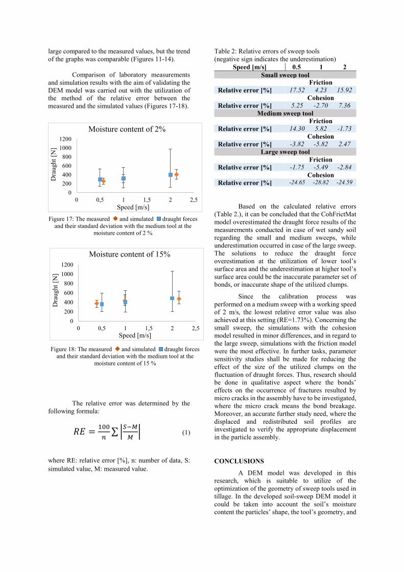
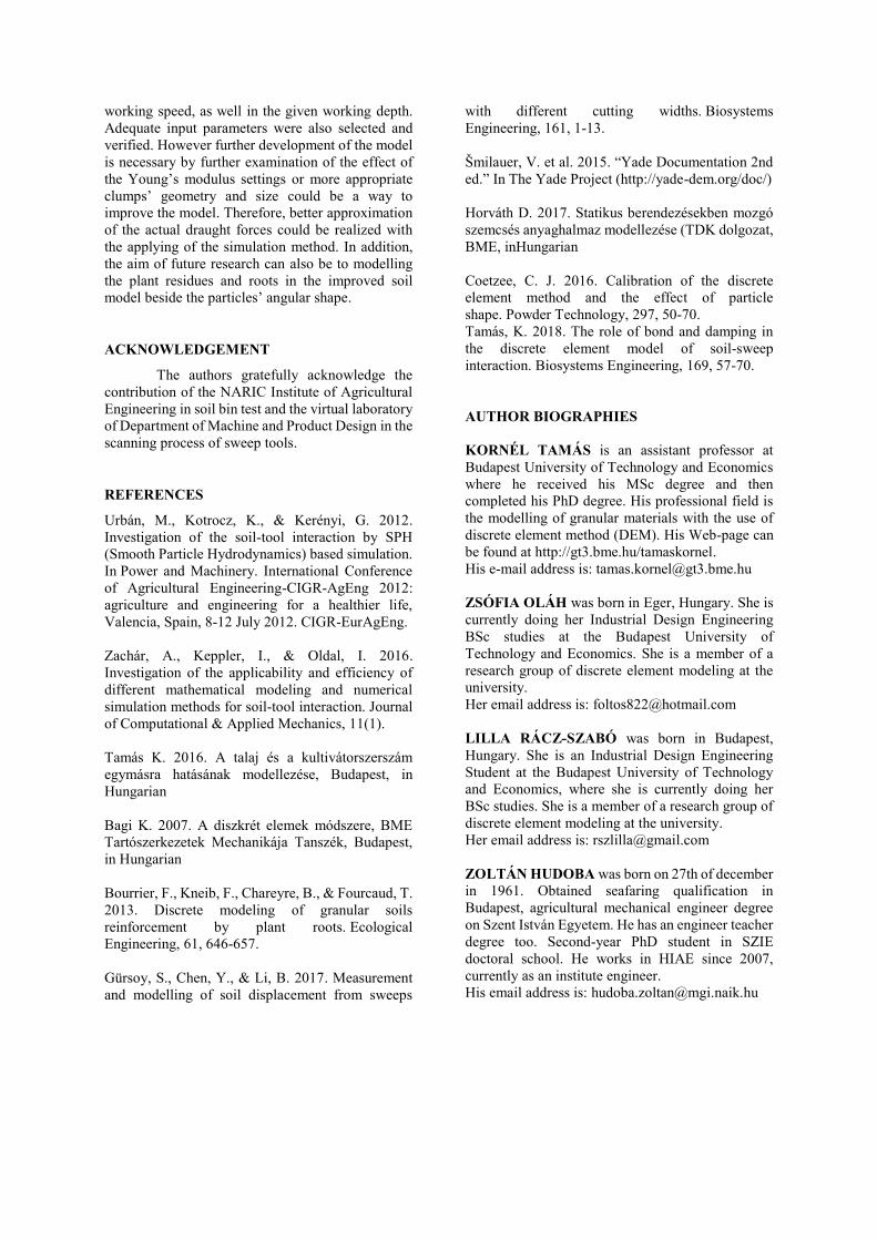
Comparison of laboratory measurements
and simulation results with the aim of validating the
DEM model was carried out with the utilization of
the method of the relative error between the
measured and the simulated values (Figures 17-18).
The relative error was determined by the
following formula:
𝑅𝐸 =100
𝑛∑ |
𝑆−𝑀
𝑀| (1)
where RE: relative error [%], n: number of data, S:
simulated value, M: measured value.
Table 2: Relative errors of sweep tools
(negative sign indicates the underestimation)
Speed [m/s] 0.5 1 2
Small sweep tool Friction
Relative error [%] 17.52 4.23 15.92
Cohesion
Relative error [%] 5.25 -2.70 7.36
Medium sweep tool
Friction
Relative error [%] 14.30 5.82 -1.73
Cohesion
Relative error [%] -3.82 -5.82 2.47
Large sweep tool
Friction
Relative error [%] -1.75 -5.49 -2.84
Cohesion
Relative error [%] -24.65 -28.82 -24.59
Based on the calculated relative errors
(Table 2.), it can be concluded that the CohFrictMat
model overestimated the draught force results of the
measurements conducted in case of wet sandy soil
regarding the small and medium sweeps, while
underestimation occurred in case of the large sweep.
The solutions to reduce the draught force
overestimation at the utilization of lower tool’s
surface area and the underestimation at higher tool’s
surface area could be the inaccurate parameter set of
bonds, or inaccurate shape of the utilized clumps.
Since the calibration process was
performed on a medium sweep with a working speed
of 2 m/s, the lowest relative error value was also
achieved at this setting (RE=1.73%). Concerning the
small sweep, the simulations with the cohesion
model resulted in minor differences, and in regard to
the large sweep, simulations with the friction model
were the most effective. In further tasks, parameter
sensitivity studies shall be made for reducing the
effect of the size of the utilized clumps on the
fluctuation of draught forces. Thus, research should
be done in qualitative aspect where the bonds’
effects on the occurrence of fractures resulted by
micro cracks in the assembly have to be investigated,
where the micro crack means the bond breakage.
Moreover, an accurate further study need, where the
displaced and redistributed soil profiles are
investigated to verify the appropriate displacement
in the particle assembly.
CONCLUSIONS
A DEM model was developed in this
research, which is suitable to utilize of the
optimization of the geometry of sweep tools used in
tillage. In the developed soil-sweep DEM model it
could be taken into account the soil’s moisture
content the particles’ shape, the tool’s geometry, and
0
200
400
600
800
1000
1200
0 0,5 1 1,5 2 2,5
Dra
ught
[N]
Speed [m/s]
Moisture content of 15%
0
200
400
600
800
1000
1200
0 0,5 1 1,5 2 2,5
Dra
ught
[N]
Speed [m/s]
Moisture content of 2%
Figure 18: The measured and simulated draught forces
and their standard deviation with the medium tool at the
moisture content of 15 %
Figure 17: The measured and simulated draught forces
and their standard deviation with the medium tool at the
moisture content of 2 %
working speed, as well in the given working depth.
Adequate input parameters were also selected and
verified. However further development of the model
is necessary by further examination of the effect of
the Young’s modulus settings or more appropriate
clumps’ geometry and size could be a way to
improve the model. Therefore, better approximation
of the actual draught forces could be realized with
the applying of the simulation method. In addition,
the aim of future research can also be to modelling
the plant residues and roots in the improved soil
model beside the particles’ angular shape.
ACKNOWLEDGEMENT
The authors gratefully acknowledge the
contribution of the NARIC Institute of Agricultural
Engineering in soil bin test and the virtual laboratory
of Department of Machine and Product Design in the
scanning process of sweep tools.
REFERENCES
Urbán, M., Kotrocz, K., & Kerényi, G. 2012.
Investigation of the soil-tool interaction by SPH
(Smooth Particle Hydrodynamics) based simulation.
In Power and Machinery. International Conference
of Agricultural Engineering-CIGR-AgEng 2012:
agriculture and engineering for a healthier life,
Valencia, Spain, 8-12 July 2012. CIGR-EurAgEng.
Zachár, A., Keppler, I., & Oldal, I. 2016.
Investigation of the applicability and efficiency of
different mathematical modeling and numerical
simulation methods for soil-tool interaction. Journal
of Computational & Applied Mechanics, 11(1).
Tamás K. 2016. A talaj és a kultivátorszerszám
egymásra hatásának modellezése, Budapest, in
Hungarian
Bagi K. 2007. A diszkrét elemek módszere, BME
Tartószerkezetek Mechanikája Tanszék, Budapest,
in Hungarian
Bourrier, F., Kneib, F., Chareyre, B., & Fourcaud, T.
2013. Discrete modeling of granular soils
reinforcement by plant roots. Ecological
Engineering, 61, 646-657.
Gürsoy, S., Chen, Y., & Li, B. 2017. Measurement
and modelling of soil displacement from sweeps
with different cutting widths. Biosystems
Engineering, 161, 1-13.
Šmilauer, V. et al. 2015. “Yade Documentation 2nd
ed.” In The Yade Project (http://yade-dem.org/doc/)
Horváth D. 2017. Statikus berendezésekben mozgó
szemcsés anyaghalmaz modellezése (TDK dolgozat,
BME, inHungarian
Coetzee, C. J. 2016. Calibration of the discrete
element method and the effect of particle
shape. Powder Technology, 297, 50-70.
Tamás, K. 2018. The role of bond and damping in
the discrete element model of soil-sweep
interaction. Biosystems Engineering, 169, 57-70.
AUTHOR BIOGRAPHIES
KORNÉL TAMÁS is an assistant professor at
Budapest University of Technology and Economics
where he received his MSc degree and then
completed his PhD degree. His professional field is
the modelling of granular materials with the use of
discrete element method (DEM). His Web-page can
be found at http://gt3.bme.hu/tamaskornel.
His e-mail address is: [email protected]
ZSÓFIA OLÁH was born in Eger, Hungary. She is
currently doing her Industrial Design Engineering
BSc studies at the Budapest University of
Technology and Economics. She is a member of a
research group of discrete element modeling at the
university.
Her email address is: [email protected]
LILLA RÁCZ-SZABÓ was born in Budapest,
Hungary. She is an Industrial Design Engineering
Student at the Budapest University of Technology
and Economics, where she is currently doing her
BSc studies. She is a member of a research group of
discrete element modeling at the university.
Her email address is: [email protected]
ZOLTÁN HUDOBA was born on 27th of december
in 1961. Obtained seafaring qualification in
Budapest, agricultural mechanical engineer degree
on Szent István Egyetem. He has an engineer teacher
degree too. Second-year PhD student in SZIE
doctoral school. He works in HIAE since 2007,
currently as an institute engineer.
His email address is: [email protected]