investigation of collision behavior of hoisting catenaries during a
TRANSCRIPT

Research ArticleInvestigation of Collision Behavior of Hoisting Catenariesduring a Lifting Cycle in Coal Mines
Jiannan Yao1,2 and Xingming Xiao1,2
1School of Mechanical and Electrical Engineering, China University of Mining & Technology, Xuzhou 221116, China2Jiangsu Key Laboratory of Mine Mechanical and Electrical Equipment, China University of Mining & Technology,Xuzhou 221116, China
Correspondence should be addressed to Xingming Xiao; xxm [email protected]
Received 4 February 2015; Revised 4 September 2015; Accepted 7 September 2015
Academic Editor: Domenico Mundo
Copyright © 2015 J. Yao and X. Xiao. This is an open access article distributed under the Creative Commons Attribution License,which permits unrestricted use, distribution, and reproduction in any medium, provided the original work is properly cited.
This investigation focused on the analyses of transverse vibrations of mine hoisting catenaries where collision between adjacentropes is more likely to occur. To support the analyses of transverse vibrations of catenaries, theoretical correlation models forlongitudinal tension and transverse vibration were first established. Based on a severe rope collision case, on-site measurementsand numerical simulations were performed. The research results indicated that the external second-order excitation frequencyinduced by axial fluctuations of head sheave was the primary excitation frequency, which was closer to the resonance frequency.Furthermore, the effects of excitation amplitude and imbalanced tension were also investigated revealing that larger excitationamplitude contributes to larger response amplitude and the maximum response amplitude of a catenary is sensitive to imbalancedrope tension. Eventually, new solutions, which will facilitate hoisting catenary operation beyond the resonance frequency range,were proposed.
1. Introduction
Steel wire ropes are widely used in many industrial applica-tions due to their high axial strength and bending flexibility[1]. In this latter application, cables connecting the minehoist and the hoisting conveyance have played a vital role inmine hoisting systems because their endurance strength andfatigue life have great effect on themine production and safetyof miners [2]. A mine multirope hoisting system is shown inFigure 1. It comprises a driving friction pulley, four hoistingropes, two sets of head sheaves, two skips, and three tail ropes.The four hoisting ropes pass from the same friction pulleyover the four singular head sheaves, forming four upper andlower catenaries, to the skip constrained to move in a verticalshaft, forming four vertical ropes hanging below the foursingular head sheaves.
The difference of material property results in the differ-ence of rope tension, which aggravates the friction of sheavegroove [3]. To keep a balance of rope tension, a tensionequilibrator is used to connect multiple ropes to hoistingconveyance as shown in Figure 2. The four main hoisting
ropes are fixed to the piston poles while the hoisting con-veyance is fixed to the cylinder blocks. Under the conditionthat one rope’s tension is higher than the others, the oil ofhigh pressure in the corresponding hydraulic cylinder will besqueezed into the other three hydraulic cylinders through aconnection pipe, which leads to a newbalance of the four ropetensions. However, due to the failure of tension equilibrator,such as the existence of creeping phenomenon between thecylinder blocks and the piston poles, the tensions in the fourhoisting ropes are not completely equal.
During mine production, the hoisting ropes are alwayssubjected to axial tensile loads and periodic external excita-tions resulting from axial fluctuations of friction pulley andhead heaves, leading to transverse vibrations of the hoistingropes. In vertical hoisting ropes, the transverse vibrations aremainly at the upper level of the shaft and usually of smallamplitude. But in catenaries, the transverse vibrations areusually intense [4]. The resonance may make two adjacentcatenaries collide with each other as shown in Figure 3,accelerating the rupture of the rope. Therefore, it is of great
Hindawi Publishing CorporationMathematical Problems in EngineeringVolume 2015, Article ID 640712, 16 pageshttp://dx.doi.org/10.1155/2015/640712

2 Mathematical Problems in Engineering
Upper heads sheave
Lower heads sheave
Vertical rope
Skip
Tail rope
Upper catenaries
Lower catenaries
Friction pulley
Figure 1: Schematic of a floor type multirope friction hoist in coalmine.
significance to explore the mechanism of the large amplitudetransverse vibrations and propose reasonable solutions toreduce the transverse amplitude.
The previous researches on the dynamics of hoistingropes in coal mines have been undertaken by some scholars.Kaczmarczyk and Ostachowicz [4, 5] derived a distributed-parameter mathematical model by employing the classicalmoving coordinate frame approach and Hamilton’s principlewith no regard to the transverse motions of head sheave ina single-rope mine drum hoist. Kaczmarczyk [6] has alsoformulated an integral longitudinal model of the catenary-vertical hoisting cable system with a periodic excitationto analyze the passage through resonance. Wang et al. [7]investigated the lateral response of the moving hoisting con-veyance in cable-guided hoisting systems and revealed thatthe maximum lateral displacement is linearly proportionalto the excitation amplitude. Cao et al. [8, 9] established thecoupled extensional-torsional model for a frictional hoistingsystemwith an oriented pulley and the extensional-torsional-lateral model for a winding hoisting system with a headheave. Mankowski and Cox [10] have studied the longitu-dinal response of mine hoisting cable to a kinetic shockload. Goroshko [11] described the longitudinal-torsionalvibrations of ropes, the elongation of which is obtainedduring untwisting and the twisting moment occurring undertension.
From the literature reviews regarding the dynamics ofhoisting ropes in coal mines, few literatures have dealt withthe problem of large amplitude transverse vibrations of hoist-ing catenaries induced by axial fluctuations of head sheavesin a multirope friction hoist in colliery. The engineeringsignificance of the present paper is to explore the mechanismof the collision behavior of the catenaries in coal minesand then propose reasonable solutions to realize resonanceavoidance. Firstly, dynamic analyses of longitudinal ropetensions were investigated. Secondly, a theoretical model oftransverse vibrations of hoisting catenaries was established.Finally, based on on-site measurements of a severe ropecollision case, the mechanism of large amplitude transversevibrations of catenaries was explored, providing theoreticalbasis for avoiding resonance.
2. Dynamic Analyses of Longitudinal Tension
2.1.Theory of Longitudinal Tension. The transverse vibrationsof catenaries are associatedwith rope tension [3]. To provide areliable basis for the analysis of collision behavior of hoistingcatenaries, dynamic analyses of longitudinal tension wereconducted. Figure 4 shows the working principle diagramof a hoisting rope in coal mines. The steel wire rope as aflexible body always subjects to dynamic load during thehoisting process. Based on the conclusion that the transversevibrations in a vertical rope are of small amplitude [4], lateraloscillations are thereby not considered in the analysis oflongitudinal tension. Considering that the effect of gravitydue to a catenary inclination is small compared to the totalquasi-static tension, the axial tensile loads along the catenaryare assumed to be equal. The continuity of deflection acrossthe head sheave requires that the dynamic tension in thecatenary equals to that at the top of the vertical rope [5].Hence, to obtain the dynamic tension in the catenary, it isimperative to explore the dynamic tension of the verticalrope.
The established coordinate system is located at the outersurface point of the sheave tangent to the vertical rope asshown in Figure 4. The elastic force instantaneously locatedin spatial position 𝑥 at time 𝑡 is represented by 𝑆(𝑡), whichcan be formulated from viscoelastic mechanics [12] as
𝑆 (𝑥, 𝑡) = 𝐸𝐴 (1 + 𝜇)
𝜕𝑢 (𝑥, 𝑡)
𝜕𝑥
, (1)
where 𝐸𝐴 and 𝜇 are the axial rigidity and viscous dampingcoefficient of the hoisting rope, respectively, and 𝑢(𝑥, 𝑡)denotes the longitudinal dynamic displacement located inspatial position 𝑥 at time 𝑡. According to the force conditionof the infinitesimal length 𝑑𝑥 as shown in Figure 4, thedynamic governing equation of the vertical rope can beformulated as
𝑆 (𝑥, 𝑡) − [𝑆 (𝑥, 𝑡) +
𝜕𝑆 (𝑥, 𝑡)
𝜕𝑥
𝑑𝑥] − 𝜌 𝑑𝑥
𝜕2𝑢 (𝑥, 𝑡)
𝜕𝑡2
= 𝜌𝑑𝑥𝑎 (𝑡) ,
(2)
where 𝜌 is the linear density of the rope and 𝑎(𝑡) denotesthe hosting acceleration with respect to hoisting time 𝑡.Substituting (1) into (2) yields
𝜕2𝑢 (𝑥, 𝑡)
𝜕𝑡2
+ 𝐸𝐴𝜌−1(1 + 𝜇)
𝜕2𝑢 (𝑥, 𝑡)
𝜕𝑥2
= −𝑎 (𝑡) . (3)
The boundary conditions of (3) can be expressed as
𝑢 (𝑥, 𝑡) = 0, 𝑥 = 0
𝐸𝐴(1 + 𝜇
𝜕
𝜕𝑡
)
𝜕𝑢 (𝑥, 𝑡)
𝜕𝑥
−
𝑄 (𝑥, 𝑡)
𝑔
𝜕2𝑢 (𝑥, 𝑡)
𝜕𝑡2
=
𝑄 (𝑥, 𝑡)
𝑔
𝑎 (𝑡) , 𝑥 = 𝑙 (𝑡) ,
(4)
where 𝑄(𝑥, 𝑡) denotes the quasi-static tension instanta-neously located in spatial position 𝑥 at time 𝑡. During

Mathematical Problems in Engineering 3
Main hoisting rope
Tension equilibrator
Cylinderblock
Pistonpole
Globevalve
Connection pipe
Working principle diagram
Figure 2: Diagram of a tension equilibrator and its working principle.
Normal Collision behavior
UppercatenariesLower
catenaries
Figure 3: Diagram of collision behavior of hoisting catenaries.
o
x
x
�(t)
a(t)
l(t)
dx
S(x, t)
L(t)
S(x, t) +𝜕S(x, t)
𝜕xdx
𝜌dx𝜕2u(x, t)
𝜕t2
Tail
Vertical
Catenary
rope
ropeLa
Figure 4: Working principle diagram of hoisting rope in coalmine.
the lifting cycles, the mass of the main hoisting rope andtail rope is time-varying. And the time-varying mass of tailrope was integrated into the mass of hoisting conveyance.
Therefore, the dynamic tension in a vertical rope during thelifting process is formulated as
𝑄 (𝑥, 𝑡)
= 𝜎𝑖{𝑚𝑒+ 𝑚𝑝+ 3𝜌𝑤[𝐿 (𝑡) + 𝐿
𝑎] + 𝜌 [𝑙 (𝑡) − 𝑥]}
⋅ [𝑔 + 𝑎 (𝑡)] ,
(5)
where the parameter 𝑚𝑒represents the mass of the skip and
the additional device, 𝑚𝑝and 𝜌
𝑤correspond to the payload
and the linear density of a hoisting tail rope, 𝐿(𝑡) is thedistance that the skip has covered until time 𝑡, 𝐿
𝑎denotes the
minimum length of a hoisting tail rope during lifting, and𝑔 is the acceleration of gravity. Due to the failure of tensionequilibrator, such as the existence of creeping phenomenonbetween cylinder blocks and piston poles, the tensions in thefour hoisting ropes are not completely equal. Therefore, animbalance coefficient 𝜎
𝑖is introduced4
∑
𝑖=1
𝜎𝑖
4
= 1, (6)
where 𝑖 represents the 𝑖th rope. If the tensions in the fourhoisting ropes are equal, 𝜎
1= 𝜎2= 𝜎3= 𝜎4= 1.
The solutions of the inhomogeneous equation (3) con-tain a general solution and a particular solution. To solve

4 Mathematical Problems in Engineering
an inhomogeneous equation, its general solution is generallysolved ahead of its particular solution. First, after havingtransformed (3) into a homogeneous equation and assumedthe dynamic displacement 𝑢(𝑡) = 𝑋(𝑥) × 𝑇(𝑡), by employingthemethod of separation of variables and using the boundaryconditions in (4), the Eigen function of the vibration of thesteel wire rope can be calculated as [13]
𝑋𝑚(𝑥, 𝑡) = sin
𝜆𝑚(𝑡)
𝑙 (𝑡)
𝑥 (𝑚 = 1, 2, 3, . . .) (7)
𝜆 tan 𝜆 =𝜌𝑙 (𝑡) 𝑔
𝑄 (𝑙 (𝑡) , 𝑡)
, (8)
where 𝜆𝑚(𝑡) denotes the 𝑚th approximate solution of tran-
scendental equation (8).Subsequently, to solve the inhomogeneous equation (3)
using the generalized coordinate method, assume that
𝑢 (𝑥, 𝑡) =
∞
∑
𝑚=1
𝑋𝑚(𝑥, 𝑡) 𝑞
𝑚(𝑡) , (9)
where 𝑞𝑚(𝑡) is the generalized coordinate with respect to time
only. The Lagrange equation of the system can be written as
𝑑
𝑑𝑡
𝜕𝐾
𝜕 (𝜕𝑞𝑚(𝑡) /𝜕𝑡)
−
𝜕𝐾
𝜕𝑞𝑚(𝑡)
+
𝜕𝑅
𝜕 (𝜕𝑞𝑚(𝑡) /𝜕𝑡)
+
𝜕𝑉
𝜕𝑞𝑚(𝑡)
= 𝑄𝑚(𝑡) (10)
𝐾 =
𝜌
2
∞
∑
𝑚=1
(
𝜕𝑞𝑚
𝜕𝑡
)
2
∫
𝑙(𝑡)
0
𝑋2
𝑚(𝑥, 𝑡) 𝑑𝑥 +
𝑄
𝑔
(
𝜕𝑞𝑚
𝜕𝑡
)
2
𝑋2
𝑚(𝑙 (𝑡) , 𝑡)
𝑉 =
𝐸𝐴
2
∞
∑
𝑚=1
𝑞2
𝑚(𝑡) ∫
𝑙(𝑡)
0
(
𝜕𝑋𝑚(𝑥, 𝑡)
𝜕𝑥
)
2
𝑑𝑥
𝑅 =
𝜇𝐸𝐴
2
∞
∑
𝑚=1
(
𝜕𝑞𝑚
𝜕𝑡
)
2
∫
𝑙(𝑡)
0
(
𝜕𝑋𝑚(𝑥, 𝑡)
𝜕𝑥
)
2
𝑑𝑥,
(11)
where 𝐾,𝑉, and 𝑅 represent the kinetic energy, potentialenergy, and dissipated energy of the system, respectively.Substituting (7), (11) into (10) yields
𝜕2𝑞𝑚(𝑡)
𝜕𝑡2
+ 𝜇
𝐸𝐴𝜆2
𝑚(𝑡)
𝜌𝑙2(𝑡)
𝜕𝑞𝑚(𝑡)
𝜕𝑡
+
𝐸𝐴𝜆2
𝑚(𝑡)
𝜌𝑙2(𝑡)
𝑞𝑚(𝑡)
=
𝜆2
𝑚(𝑡) 𝑄𝑚(𝑡)
𝜌𝑙2(𝑡) ∫
𝑙(𝑡)
0(𝜕𝑋𝑚(𝑥, 𝑡) /𝜕𝑥)
2
𝑑𝑥
.
(12)
Solving (12) yields
𝑞𝑚(𝑡) =
𝜆2
𝑚(𝑡)
𝜌𝑙2(𝑡) ∫
𝑙(𝑡)
0(𝜕𝑋𝑚(𝑥, 𝑡) /𝜕𝑥)
2
𝑑𝑥
𝑒−ℎ𝑚𝑡
𝑤𝑚(𝑡)
⋅ ∫
𝑡
0
𝑒ℎ𝑚𝜏𝑄𝑚(𝜏) sin𝜔
𝑚(𝑡 − 𝜏) 𝑑𝜏,
(13)
where
𝑄𝑚(𝑡) =
𝜌𝑙 (𝑡) 𝑎 (𝑡)
𝜆𝑚(𝑡)
ℎ𝑚(𝑡) = √
𝐸𝐴𝜆2
𝑚(𝑡) 𝜇
2𝜌𝑙2(𝑡)
𝜔𝑚(𝑡) = √
𝐸𝐴𝜆2
𝑚(𝑡)
𝜌𝑙2(𝑡)
(1 −
𝜇
2
).
(14)
Therefore, the solution for the inhomogeneous equation (3)can be got as
𝑢 (𝑥, 𝑡) =
∞
∑
𝑚=1
sin(𝜆𝑚(𝑡)
𝑙 (𝑡)
𝑥) 𝑞𝑚(𝑡) . (15)
Due to 𝑇(𝑥, 𝑡), the dynamic tension instantaneously locatedin spatial position 𝑥 at time 𝑡; is the sum of the elastic force𝑆(𝑡) and the quasi-static force 𝑄(𝑥, 𝑡); therefore,
𝑇 (𝑥, 𝑡) = 𝑄 (𝑥, 𝑡) 𝑎 (𝑡) 𝑔−1{[1 + 𝛼 (𝑡) − 𝛼 (𝑡) 𝑥𝑙
−1(𝑡)]
− 4𝛼 (𝑡)
∞
∑
𝑚=1
{[
cos (𝜆𝑚(𝑡) 𝑥/𝑙 (𝑡))
𝜆2
𝑚(𝑡) (2𝜆
𝑚(𝑡) + sin 2𝜆
𝑚(𝑡))
]
⋅ 𝑒−ℎ𝑚(𝑡)𝑡[cos𝜔
𝑚(𝑡) 𝑡 −
ℎ𝑚(𝑡)
𝜔𝑚(𝑡)
sin𝜔𝑚(𝑡) 𝑡]}}
+ 𝑄 (𝑥, 𝑡) ,
(16)
where
𝛼 (𝑡) =
𝜌𝑙 (𝑡) 𝑔
𝑄 (𝑙 (𝑡) , 𝑡)
. (17)
2.2. Simulation Analyses. According to (16) in Section 2.1,the dynamic tensions in a vertical rope at the skip end andsheave end were calculated. Two typical working conditions(ascending with no payload and full payload) were taken intoaccount.The upwardmovement profile, as shown in Figure 5,is divided into seven stages.The velocity function V(𝑡) is givenby the following formula:
V𝑖(𝑡) = V
0𝑖+ 𝑎𝑖Δ𝑡𝑖, (𝑖 = 1, 2, . . . , 7) , (18)
where the initial velocities at the 1st to 7th stage, V01
toV07, are 0, 0.59m/s, 9.31m/s, 9.31m/s, 1.76m/s, 1.76m/s, and
0.72m/s, respectively, the accelerations at the 1st to 7th stage

Mathematical Problems in Engineering 5
0 50 1000
200
400
600
800Le
ngth
(m)
Hoisting time (s)
Vertical hoistingrope
(a)
0 50 1000
200
400
600
800
Leng
th (m
)
Hoisting time (s)
Hoisting tailrope
(b)
0 50 1000
2
4
6
8
10
Velo
city
(m/s
)
Hoisting time (s)
(c)
0 50 100Hoisting time (s)
6
1
2
4
3 5 7
0.5
0
−0.5
−1
Acce
lera
tion
(m/s2)
(d)
Figure 5: Upward movement profile of the skip: (a) time-varying length of the vertical hoisting rope; (b) time-varying length of the hoistingtail rope; (c) hosting velocity; (d) hoisting acceleration. The seven stages are marked in (d).
are 0.21m/s2, 0.4m/s2, 0, −0.6m/s2, 0, −0.52m/s2, and 0,respectively, and the hoisting time at the 1st to 7th stageare 2.8 s, 21.8 s, 53.5 s, 12.6 s, 9.3 s, 2 s, and 4 s in sequence.According to the velocity function V(𝑡), the time-varyinglength of the vertical rope and that of the tail rope are shownin Figures 5(a) and 5(b). The hoisting parameters are shownin Table 1.
Figure 6 shows the simulation results of rope tensionsat the skip end and the sheave end under the two typicalworking conditions. To obtain a theoretical balance value,the tension imbalance coefficient 𝜎
𝑖(𝑖 = 1, 2, 3, 4) was set
as 1. The seven stages are marked in the red dashed linecorresponding to those in Figure 5(d). It is obviously seenthat the fluctuating rope tension occurs at the accelerationor deceleration hoisting stages, such as the first, second,fourth, and sixth hoisting stage as shown in Figure 6, anddecreases with the hoisting time rapidly. During the constantspeed hoisting stages (the third, fifth, and seventh hoistingstage shown in Figure 6), the variation of rope tension is
stable without fluctuation. Sudden change of rope tensionat transitional stages between adjacent lifting stages resultsfrom the internal load and the flexible impact due to thesudden change of acceleration.Under the two typical workingconditions, the overall rise of rope tension at the skip endis attributed to the increasing hoisting tail rope length;meanwhile, the rope tension at the sheave end is basicallyconstant during the constant speed hoisting stage.
Considering the conclusionmentioned in Section 2.1 thatthe dynamic tension in the catenary equals to that at the topof the vertical rope, the response curves at the sheave end inFigure 6 also represent the tensions in catenaries. In terms ofindustrial applications, during the maximum constant speedstage, the transverse vibrations of hoisting catenaries aremost intense and collision between two adjacent catenaries istherebymore likely to occur. Hence, the tensions at the sheaveend at the third hoisting stage are of interest and adopted toconduct the analysis of the transverse vibrations of hoistingcatenaries.

6 Mathematical Problems in Engineering
Table 1: Parameters of the hoisting system.
Parameters of the hoisting system Notation Parameter valueRope spacing (mm) 𝐿
𝑅350
Diameter of hoisting rope (mm) 𝑑 43Diameter of the head sheave (m) 𝐷 4.5Maximum hoisting speed (m/s) V
𝑚9.31
Length of the lower inclined catenary (m) 𝐿𝑐
43.74Maximum length of vertical hoisting rope (m) 𝑙max 699Minimum length of hoisting tail rope (m) 𝐿
𝑎14
Mass of full payload (kg) 𝑚𝑝
18000Mass of the skip and its additional devices (kg) 𝑚
𝑒17983
Viscous damping coefficient 𝜇 0.0056Young’s modulus of the hoisting rope (Pa) 𝐸 1 × 10¹¹
Cross-sectional area of the hoisting rope (mm2) 𝐴 1452.2Mass of the hoisting rope per unit meter (kg/m) 𝜌 7.86Mass of the hoisting tail rope per unit meter (kg/m) 𝜌
𝑤10.48
0 20 40 60 80 100Hoisting time t (s)
Dyn
amic
tens
ion
(N)
Skip end, no payloadSheave end, no payload
Skip end, full payloadSheave end, full payload
1
36
2754
2
1.8
1.6
1.4
1.2
1
0.8
0.6
0.4
×105
Figure 6: Dynamic tension at the skip end and sheave end duringhoisting process.
3. Theoretical Model of Transverse Vibration
To describe the transverse vibrations of hoisting catenaries, afixed coordinate system 𝑜𝑥𝑦 is established. Considering thatthe effect of gravity due to a catenary inclination is small com-pared to the total quasi-static tension, the hoisting catenariescan be viewed as four horizontally moving catenaries withconstant length 𝐿 in the 𝑥-𝑦 plane as shown in Figure 7 [4].The four catenaries wrap around the same friction pulley andattach to the four singular sheaves, respectively. Therefore,the friction pulley is modeled as a fixed-center pulley withaxial fluctuating displacement specified by 𝑒
0(𝑡), and the four
singular head sheaves aremodelled as four particles subjectedto axial fluctuating displacement specified by 𝑒
1(𝑡), 𝑒2(𝑡),
Head sheavesFriction pulley
y
o x
�
L
e4(t)
e3(t)
e2(t)
e1(t)
e0(t)
Figure 7: Diagram of the transverse vibration model of hoistingcatenaries.
Uppercatenaries
Lowercatenaries
1#2#
3#4#
Origin
“yo”
Figure 8: Processed image of the transverse vibration displace-ments.
𝑒3(𝑡), and 𝑒
4(𝑡), respectively, where 𝑡 is the hoisting time. Due
to the industrial fact that axial fluctuations of head sheavesexcite the transverse vibrations of hoisting catenaries, therope vibrations are predominantly along the 𝑦 direction inplane as shown in Figure 7. Therefore, regardless of spatialmotions, the planar vibrations are of interest to explore thecollision mechanism of the catenaries.
In the present study, considering that the transversedisplacement of the catenary is very small compared tothe catenary length, and the rope tension is sufficiently solarge that its variation due to extension of the rope can benegligible. Therefore, a linear model can be introduced to

Mathematical Problems in Engineering 7
Rotatingsheave 1
Rotatingsheave 2
Rotatingsheave 3
Rotatingsheave 4
Inductivedisplacement
transducerHoisting
ropeRetainer
Figure 9: Measurement of the axial fluctuating displacements ofhead sheaves.
Outer ring flangeInductive
displacementtransducer
Figure 10: Measurement of the axial fluctuating displacements offriction pulley.
describe the lateral oscillation of the catenary in coal mine[14–16]:
𝜌 (𝑦𝑡𝑡+ 𝑎 (𝑡) 𝑦
𝑥+ 2V (𝑡) 𝑦
𝑥𝑡+ V2 (𝑡) 𝑦
𝑥𝑥) = 𝑇𝑦
𝑥𝑥,
0 ≤ 𝑥 ≤ 𝐿,
(19)
where 𝑦(𝑥, 𝑡) is the transverse displacement of the ropeparticle instantaneously located in spatial position 𝑥 at time 𝑡and the subscripts𝑥 and 𝑡 denote partial differentiation,𝜌 and𝐿 are the linear density and length of the hoisting catenary,𝑎(𝑡) and V(𝑡) are the hoisting acceleration and velocity,respectively, and 𝑇 is the constant tension in the catenaryat the constant maximum hoisting speed stage (the thirdhoisting stage in Figure 6). The nonhomogeneous boundaryconditions resulting from axial fluctuations of friction pulleyand head sheaves are defined by
𝑦 (0, 𝑡) = 𝑒0(𝑡) ,
𝑦 (𝐿, 𝑡) = 𝑒𝑖(𝑡) (𝑖 = 1, 2, 3, 4) ,
(20)
where 𝑖 represents the 𝑖th catenary as shown in Figure 7.Using the method from literature [17], the transverse dis-placement can be expressed as
𝑦 (𝑥, 𝑡) = 𝑢 (𝑥, 𝑡) + ℎ (𝑥, 𝑡) (21)
ℎ (𝑥, 𝑡) = 𝑒0(𝑡) +
[𝑒𝑖(𝑡) − 𝑒
0(𝑡)] 𝑥
𝐿
, (22)
Oil pressure sensor
Tension equilibrator
1# 2#
Globe valve
3# 4#
Figure 11: Measurement of the oil pressure of the tension equilibra-tor.
1 2 3 401020304050
Upper catenary
1 2 3 40
50
100
150
200
Number
Number
Lower catenary
Max
imum
ampl
itude
(mm
)M
axim
um am
plitu
de (m
m)
Full payloadNo payload
Full payloadNo payload
168.8mm171.8mm
42.58mm26.5mm
109.8mm
29.22mm28.26mm27.4mm
9.2mm13.33mm
18.17mm
11.73mm15mm
22.88mm22.6mm
12.3mm
Figure 12: Maximum transverse amplitudes of the catenaries.
where 𝑢(𝑥, 𝑡) is the part that satisfies the homogeneousboundary conditions and ℎ(𝑥, 𝑡) is the nonhomogeneouspart. Substituting (21) into (19) yields
𝜌 (𝑢𝑡𝑡+ 𝑎 (𝑡) 𝑢
𝑥+ 2V (𝑡) 𝑢
𝑥𝑡+ V2 (𝑡) 𝑢
𝑥𝑥) − 𝑇𝑢
𝑥𝑥
= 𝑓 (𝑥, 𝑡) , 0 < 𝑥 < 𝐿
𝑓 (𝑥, 𝑡)
= −𝜌 [ℎ𝑡𝑡+ 𝑎 (𝑡) ℎ
𝑥+ 2V (𝑡) ℎ
𝑥𝑡+ V2 (𝑡) ℎ
𝑥𝑥]
+ 𝑇ℎ𝑥𝑥,
(23)
where 𝑓(𝑥, 𝑡) is the additional forcing term induced bytransforming the governing equation with time dependent
8 Mathematical Problems in Engineering
−40
−20
0
20
40
Am
plitu
de (m
m)
Am
plitu
de (m
m)
Am
plitu
de (m
m)
Am
plitu
de (m
m)
Lower catenary 1
0 10 20 30 40 0 10 20 30 40
−100
0
100
Lower catenary 2
−200
−100
0
100
200Lower catenary 3
0 10 20 30 40 0 10 20 30 40−200
−100
0
100
200
Time (s)Time (s)
Time (s)Time (s)
Lower catenary 4
Peak value 28.26mm
Peak value 168.8mmPeak value 171.8mm
Peak value 109.8mm
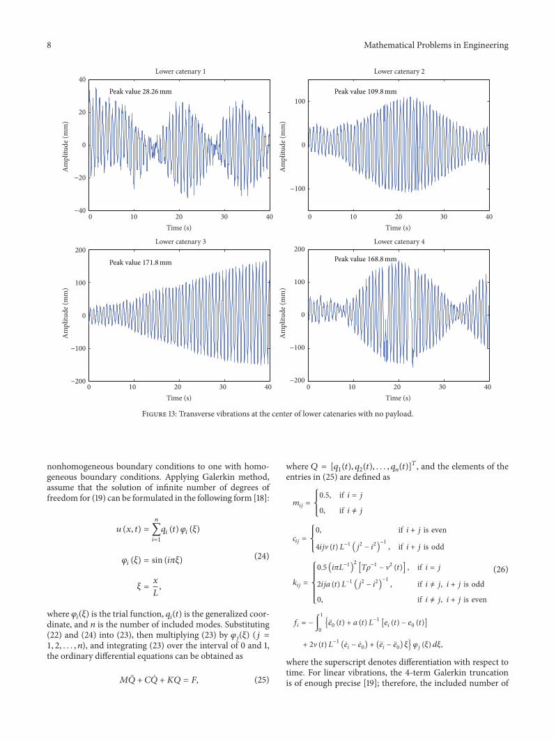
Figure 13: Transverse vibrations at the center of lower catenaries with no payload.
nonhomogeneous boundary conditions to one with homo-geneous boundary conditions. Applying Galerkin method,assume that the solution of infinite number of degrees offreedom for (19) can be formulated in the following form [18]:
𝑢 (𝑥, 𝑡) =
𝑛
∑
𝑖=1
𝑞𝑖(𝑡) 𝜑𝑖(𝜉)
𝜑𝑖(𝜉) = sin (𝑖𝜋𝜉)
𝜉 =
𝑥
𝐿
,
(24)
where 𝜑𝑖(𝜉) is the trial function, 𝑞
𝑖(𝑡) is the generalized coor-
dinate, and 𝑛 is the number of included modes. Substituting(22) and (24) into (23), then multiplying (23) by 𝜑
𝑗(𝜉) (𝑗 =
1, 2, . . . , 𝑛), and integrating (23) over the interval of 0 and 1,the ordinary differential equations can be obtained as
𝑀�̈� + 𝐶�̇� + 𝐾𝑄 = 𝐹, (25)
where 𝑄 = [𝑞1(𝑡), 𝑞2(𝑡), . . . , 𝑞
𝑛(𝑡)]𝑇, and the elements of the
entries in (25) are defined as
𝑚𝑖𝑗=
{
{
{
0.5, if 𝑖 = 𝑗
0, if 𝑖 ̸= 𝑗
𝑐𝑖𝑗=
{
{
{
0, if 𝑖 + 𝑗 is even
4𝑖𝑗V (𝑡) 𝐿−1 (𝑗2 − 𝑖2)−1
, if 𝑖 + 𝑗 is odd
𝑘𝑖𝑗=
{{{{
{{{{
{
0.5 (𝑖𝜋𝐿−1)
2
[𝑇𝜌−1− V2 (𝑡)] , if 𝑖 = 𝑗
2𝑖𝑗𝑎 (𝑡) 𝐿−1(𝑗2− 𝑖2)
−1
, if 𝑖 ̸= 𝑗, 𝑖 + 𝑗 is odd
0, if 𝑖 ̸= 𝑗, 𝑖 + 𝑗 is even
𝑓𝑖= −∫
1
0
{ ̈𝑒0(𝑡) + 𝑎 (𝑡) 𝐿
−1[𝑒𝑖(𝑡) − 𝑒
0(𝑡)]
+ 2V (𝑡) 𝐿−1 ( ̇𝑒𝑖− ̇𝑒0) + ( ̈𝑒𝑖− ̈𝑒0) 𝜉} 𝜑𝑗(𝜉) 𝑑𝜉,
(26)
where the superscript denotes differentiation with respect totime. For linear vibrations, the 4-term Galerkin truncationis of enough precise [19]; therefore, the included number of
Mathematical Problems in Engineering 9
0
5
10
15Lower catenary 1
Am
plitu
de (m
m)
Am
plitu
de (m
m)
Am
plitu
de (m
m)
Am
plitu
de (m
m)
0 1 2 3 4 5 0 1 2 3 4 50
20
40
60Lower catenary 2
0
20
40
60
80
Lower catenary 3
0 1 2 3 4 5 0 1 2 3 4 50
20
40
60
Lower catenary 4
Frequency (Hz)Frequency (Hz)
Frequency (Hz)Frequency (Hz)
y: 55.23mmx: 1.32Hz
y: 74.22mmx: 1.33Hz
y: 49.07mmx: 1.32Hz
y: 12.27mmx: 1.31Hz
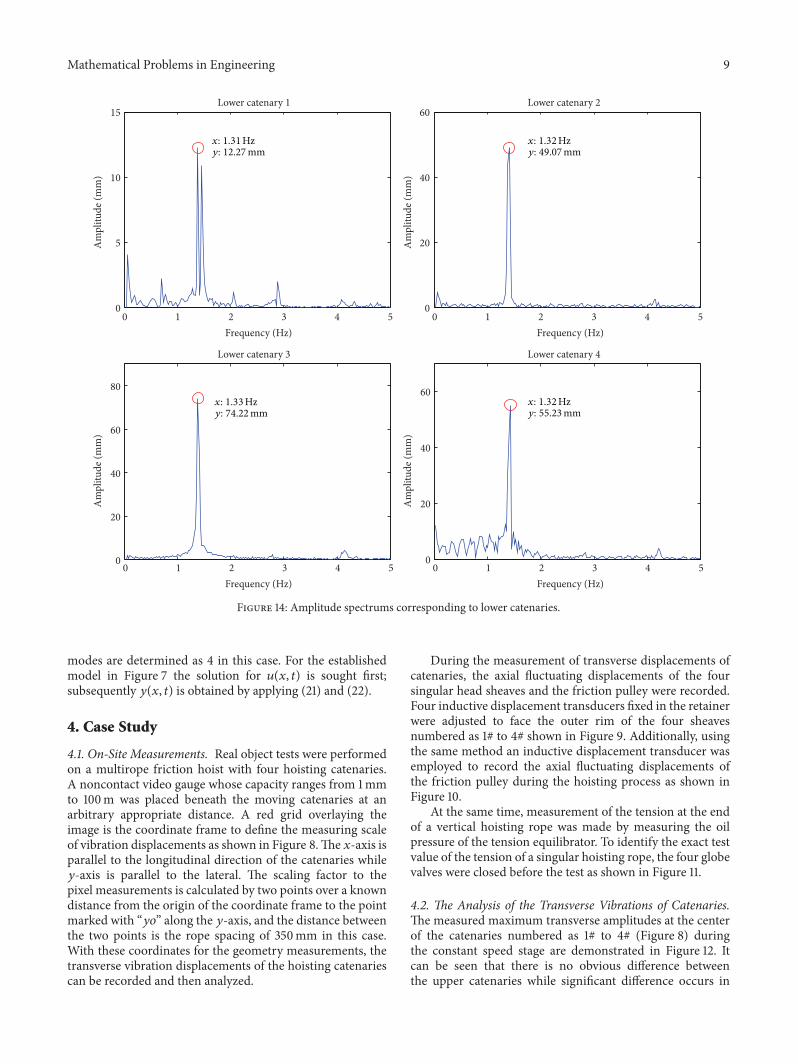
Figure 14: Amplitude spectrums corresponding to lower catenaries.
modes are determined as 4 in this case. For the establishedmodel in Figure 7 the solution for 𝑢(𝑥, 𝑡) is sought first;subsequently 𝑦(𝑥, 𝑡) is obtained by applying (21) and (22).
4. Case Study
4.1. On-Site Measurements. Real object tests were performedon a multirope friction hoist with four hoisting catenaries.A noncontact video gauge whose capacity ranges from 1mmto 100m was placed beneath the moving catenaries at anarbitrary appropriate distance. A red grid overlaying theimage is the coordinate frame to define the measuring scaleof vibration displacements as shown in Figure 8.The 𝑥-axis isparallel to the longitudinal direction of the catenaries while𝑦-axis is parallel to the lateral. The scaling factor to thepixel measurements is calculated by two points over a knowndistance from the origin of the coordinate frame to the pointmarked with “𝑦𝑜” along the 𝑦-axis, and the distance betweenthe two points is the rope spacing of 350mm in this case.With these coordinates for the geometry measurements, thetransverse vibration displacements of the hoisting catenariescan be recorded and then analyzed.
During the measurement of transverse displacements ofcatenaries, the axial fluctuating displacements of the foursingular head sheaves and the friction pulley were recorded.Four inductive displacement transducers fixed in the retainerwere adjusted to face the outer rim of the four sheavesnumbered as 1# to 4# shown in Figure 9. Additionally, usingthe same method an inductive displacement transducer wasemployed to record the axial fluctuating displacements ofthe friction pulley during the hoisting process as shown inFigure 10.
At the same time, measurement of the tension at the endof a vertical hoisting rope was made by measuring the oilpressure of the tension equilibrator. To identify the exact testvalue of the tension of a singular hoisting rope, the four globevalves were closed before the test as shown in Figure 11.
4.2. The Analysis of the Transverse Vibrations of Catenaries.Themeasured maximum transverse amplitudes at the centerof the catenaries numbered as 1# to 4# (Figure 8) duringthe constant speed stage are demonstrated in Figure 12. Itcan be seen that there is no obvious difference betweenthe upper catenaries while significant difference occurs in

10 Mathematical Problems in Engineering
−2
0
2
Lower head sheave 1
0 1 2 3 4 5 0 1 2 3 4 5−10
−5
0
5
10
15Lower head sheave 2
−5
0
5
Lower head sheave 3
Axi
al d
ispla
cem
ent (
mm
)
Axi
al d
ispla
cem
ent (
mm
)
Axi
al d
ispla
cem
ent (
mm
)
Axi
al d
ispla
cem
ent (
mm
)
0 1 2 3 4 5 0 1 2 3 4 5−10
−5
0
5
10
15Lower head sheave 4
Time (s)Time (s)
Time (s)Time (s)
Peak-to-peak value 17mmPeak-to-peak value 8mm
Peak-to-peak value 16mmPeak-to-peak value 4.5mm
Figure 15: Partial fluctuating waveforms of axial fluctuations of head sheaves.
the lower catenaries. Especially at the center of the lowercatenary 2# catenary to 4#, the maximum amplitudes underthe condition of no load are much larger than those withfull payload. The rope spacing among the four catenaries is350mm; therefore, if the maximum transverse amplitudes oftwo adjacent catenaries both exceed the dangerous thresholdof 175mm, collision will be resulted in and the rupture of therope is thereby accelerated. Hence, the situations at the centerof the lower catenary 3# and catenary 4# shown in Figure 12can be identified as a fault state because they are much closeto the dangerous threshold.
To analyze the behavior of large transverse amplitude ofcatenaries, the transverse displacements during the constantspeed stage at the center of the lower catenaries under thecircumstance of no payload were given in Figure 13. Usingfast Fourier transform (FFT), the corresponding amplitudespectrums were illustrated in Figure 14. It can be seen fromFigure 13 that clear resonance occurred in lower catenary 2#to catenary 4#, and themain vibration frequencies are 1.31Hz,1.32Hz, 1.33Hz, and 1.32Hz relating to lower catenary 1# tocatenary 4#, respectively.
4.3. The Analysis of External Displacement Excitations. Themeasured axial fluctuating displacements of lower headsheaves 1# to 4# at the constant speed stage are shown inFigure 15, and the corresponding amplitude spectrums aregiven in Figure 16. The catenaries share the same frictionpulley, so they have the same axial fluctuating displacementsas shown in Figure 17. The peak-to-peak values of the axialfluctuations of lower head sheaves 1# to 4# are 4.5mm, 16mm,8mm, and 17mm, respectively. The rotational frequency ofthe head sheave is 𝑓 = V
𝑚/𝜋𝐷 = 0.66Hz, which also
acts as the fundamental excitation frequency of the externalexcitations. And it can be inferred from Figures 16 and 17that the first three-order frequency components play thedominating roles in the external displacement excitations.Furthermore, the first three-order excitation amplitudes inthe friction pulley are approximately zero which are far lessthan those in the head sheaves; thus, they can be ignored inthis case.
4.4. The Analysis of the Tensions of Catenaries. The tensionof a catenary cannot be measured directly while it can be

Mathematical Problems in Engineering 11
0
0.5
1
1.5
2
2.5Lower head sheave 1
0 1 2 3 4 5 0 1 2 3 4 50
2
4
6Lower head sheave 2
0
1
2
3
4Lower head sheave 3
Am
plitu
de (m
m)
Am
plitu
de (m
m)
Am
plitu
de (m
m)
Am
plitu
de (m
m)
0 1 2 3 4 5 0 1 2 3 4 50
2
4
6
8
Frequency (Hz)Frequency (Hz)
Frequency (Hz)Frequency (Hz)
Lower head sheave 4
2x
2x
3x
3x
1x
1x2x 3x1x
2x 3x1x
0.33mm
1.9mm
0.27mm
2.06mm
6.1mm
1.46mm
2.98mm
3.97mm
2.34mm
0.57mm
3.01mm
0.7mm
Figure 16: Amplitude spectrums corresponding to axial fluctuations of head sheaves.
0 1 2 3 4 53
3.5
4
4.5
5
Time (s)
Am
plitu
de (m
m)
(a)
0 1 2 3 4 50
0.1
0.2
0.3
Frequency (Hz)
Am
plitu
de (m
m)
0.18mm
0.3mm0.22mm
2x 3x1x
(b)
Figure 17: Measured data of axial fluctuations of friction pulley.
predicted by calculating (16). In this case, the tension atthe skip end can be obtained by measuring the oil pressureof the tension equilibrator. After linear transformation andmedian filtering, the tension-time curves during the upwardmovement were presented as curve 2 in Figure 18. Curves 1and 3 are the theoretical balance curves relating to sheaveend and skip end which are calculated by substituting thepractical parameters listed in Table 1 into (16). According tothe conclusion mentioned in Section 2.1 that the dynamictension in the catenary equals that at the vertical rope top
end, therefore, curve 1 shown in Figure 18 also represents thetheoretical balance tension of a catenary. It can be concludedfrom Figure 18 that the tensions in the four catenaries areexactly unbalanced.Through the comparison of curves 2 and3, the unbalance coefficients for the tensions in lower catenary1# to catenary 4# referred to as 𝜎
1, 𝜎2, 𝜎3, and 𝜎
4can be
determined as 0.95, 1.01, 1.03, and 1.01.
4.5. Simulation and Validation. In Section 4.3, it has beenconcluded that the first three-order frequency components

12 Mathematical Problems in Engineering
2
4
6
8
10
12
Rope tension 1#
0 50 100 0 50 1002
4
6
8
10
12
Rope tension 2#
2
4
6
8
10
12
Rope tension 3#
Tens
ion
(N)
Tens
ion
(N)
Tens
ion
(N)
Tens
ion
(N)
0 50 100 0 50 1002
4
6
8
10
12
Rope tension 4#
Hoisting time (s) Hoisting time (s)
Hoisting time (s) Hoisting time (s)
×104×104
×104×104
1
2
3
1
2
3
1
2
3
1
2
3
Figure 18: Contrast of theoretical and practical rope tensions.
play the dominating roles in the external displacement exci-tations and thus can be specified by 𝐴
1sin(𝑤𝑡), 𝐴
2sin(2𝑤𝑡),
and 𝐴3sin(3𝑤𝑡), where 𝐴
1, 𝐴2, and 𝐴
3are the first three-
order harmonic amplitudes which can be determined fromFigure 16, 𝑤 is the angular velocity of the head sheave. Themaximum constant hoisting speed in this case is V
𝑚=
9.31m/s; then the angular velocity during the constant speedstage can be calculated as 4.14 rad/s from the formula 𝑤 =
2V𝑚/𝐷, where 𝐷 is the diameter of head sheave valuing
4.5m. According to Figure 6, under the circumstance ofno payload, the theoretical balance tension in a catenaryduring the constant speed stage is 99990N. Additionally, theunbalance coefficients for the tensions in lower catenary 1#to catenary 4# referred to as 𝜎
1, 𝜎2, 𝜎3, and 𝜎
4are 0.95, 1.01,
1.03, and 1.01, respectively.Therefore, the exact tensions in thelower catenary 1# to catenary 4# can be derived as 94990N,100990N, 103000N, and 100990N. Using the practical hoist-ing parameters and substituting the exact rope tensions andthe first three-order excitations shown in Figure 16 into (25)and (26), the response amplitudes at the center of the four
catenaries in time domain are demonstrated in Figures 19–22. It can be seen that the first- and third-order responseamplitudes are much smaller than the second-order andthereby can be negligible. The simulation maximum second-order response amplitudes at the center of the lower catenary1# to catenary 4# are 22.34mm, 104.3mm, 172.2mm, and160.2mm, respectively, which aremuch close to themeasured28.26mm, 109.8mm, 171.8mm, and 168.8mm as shown inFigure 13.The differencemay result frommodel errors, whichare acceptable when the primary purpose is fault diagnosis.Furthermore, the shapes of the vibrating waveforms underthe second-order excitations in Figures 19–22 are muchsimilar to the measured as shown in Figure 13. Therefore, thevalidity and applicability of the established linear transversevibration model can be confirmed. What is more, the mainvibration frequencies of the measured data in lower catenary1# to catenary 4# are 1.31Hz, 1.32Hz, 1.33Hz, and 1.32Hz,which are approximately double the rotational frequency;hence, it can be concluded that the second-order harmonicfrequency is the primary excitation frequency in this case.

Mathematical Problems in Engineering 13
0 5 10 15 20 25 30 35 40−0.2
0
0.2
Time (s)
Resp
onse
ampl
itude
(mm
)
(a) Excitation: 0.33 sin(4.14𝑡)
0 5 10 15 20 25 30 35 40−50
0
50
Time (s)
Resp
onse
ampl
itude
(mm
)
(b) Excitation: 1.9 sin(8.28𝑡)
0 5 10 15 20 25 30 35 40−1
0
1
Time (s)
Resp
onse
ampl
itude
(mm
)
(c) Excitation: 0.27 sin(12.42𝑡)
Figure 19: Simulation of transverse vibrations in lower catenary 1.
0 5 10 15 20 25 30 35 40−1
0
1
Time (s)
Resp
onse
ampl
itude
(mm
)
(a) Excitation: 2.34 sin(4.14𝑡)
0 5 10 15 20 25 30 35 40−100
0
100
Time (s)
Resp
onse
ampl
itude
(mm
)
(b) Excitation: 3.97 sin(8.28𝑡)
0 5 10 15 20 25 30 35 40−10
0
10
Time (s)
Resp
onse
ampl
itude
(mm
)
(c) Excitation: 2.98 sin(12.42𝑡)
Figure 20: Simulation of transverse vibrations in lower catenary 2.
4.6. Fault Analysis. To account for the large transverse ampli-tudes studied in this case, the maximum response ampli-tudes in the four lower catenaries with varying excitationfrequencies are plotted in Figure 23. Considering the con-clusion given in Section 4.5 that the second-order harmonicfrequency is the primary excitation frequency, the excitationamplitudes are thus chosen as 1.9mm, 3.97mm, 3.01mm,
0 5 10 15 20 25 30 35 40−0.5
0
0.5
Time (s)
Resp
onse
ampl
itude
(mm
)
(a) Excitation: 0.7 sin(4.14𝑡)
0 5 10 15 20 25 30 35 40−200
0
200
Time (s)
Resp
onse
ampl
itude
(mm
)
(b) Excitation: 3.01 sin(8.28𝑡)
0 5 10 15 20 25 30 35 40−2
0
2
Time (s)
Resp
onse
ampl
itude
(mm
)(c) Excitation: 0.57 sin(12.42𝑡)
Figure 21: Simulation of transverse vibrations in lower catenary 3.
0 5 10 15 20 25 30 35 40−0.5
0
0.5
Time (s)
Resp
onse
ampl
itude
(mm
)
(a) Excitation: 1.46 sin(4.14𝑡)
0 5 10 15 20 25 30 35 40−200
0
200
Time (s)
Resp
onse
ampl
itude
(mm
)
(b) Excitation: 6.1 sin(8.28𝑡)
0 5 10 15 20 25 30 35 40−10
0
10
Time (s)
Resp
onse
ampl
itude
(mm
)
(c) Excitation: 2.06 sin(12.42𝑡)
Figure 22: Simulation of transverse vibrations in lower catenary 4.
and 6.1mm as shown in Figure 22. And the rope tensionsin Figures 23(a)–23(d) are 94990N, 100990N, 103000N, and100990N relative to lower catenary 1# to catenary 4#, whichare the same as those in Section 4.5. The resonance pointsreferred to as P1, P2, P3, and P4 in Figure 22 are (7.79 rad/s,186.4mm), (8.08 rad/s, 397.7mm), (8.2 rad/s, 306.6mm), and(8.08 rad/s, 611.1mm). It is obvious that the second-order

14 Mathematical Problems in Engineering
0
50
100
150
200
0 5 10 15
Max
imum
ampl
itude
(mm
)
Frequency (rad/s)
Excitation:
1 32
P1
1.9sin (wt)
(a)
0 5 10 15
Max
imum
ampl
itude
(mm
)
0
100
200
300
400
500
Frequency (rad/s)
Excitation:
1
23
P2
3.97sin (wt)
(b)
0 5 10 150
100
200
300
400
Max
imum
ampl
itude
(mm
)
Frequency (rad/s)
Excitation:
1 3
2
P3
3.01sin (wt)
(c)
Max
imum
ampl
itude
(mm
)
0 5 10 150
200
400
600
800
Frequency (rad/s)
Excitation:
1 3
2
P4
6.1sin (wt)
(d)
Figure 23: Amplitude-frequency curves of the transverse vibrations in catenaries.
excitation frequency of 8.28 rad/s is closer to the resonancefrequency than the first- and third-order, accounting for thefact that the second-order amplitude is much larger than thefirst- and third-order.
Additionally, to explore the effect of unbalanced ropetensions on the transverse vibrations of catenaries, underthe excitations of𝐴
1sin(2𝑤𝑡),𝐴
2sin(2𝑤𝑡),𝐴
3sin(2𝑤𝑡), and
𝐴4sin(2𝑤𝑡) where 𝐴
1to 𝐴4are the second-order excitation
amplitudes studied in this case, the response curves ofmaximum amplitudes are obtained by varying the imbalancecoefficient of tension as shown in Figure 24. It can be inferredthat larger excitation amplitude contributes to larger responseamplitude. Above all, under the circumstance of unbalancedcoefficient 1.05, the smallest response amplitude is even245mm with the minimum excitation amplitude 1.9mm.The rope spacing studied in this case is 350mm, so if twocatenaries are suffering the same unbalanced coefficient 1.05and the second-order excitation amplitudes are even the sameminimum value of 1.9mm, the sum of the two maximumtransverse amplitudes at the center of the catenaries willbe 490mm exceeding the rope spacing and the dangerouscollision are absolutely caused.
5. Summary and Conclusions
The transverse vibrations in the hoisting catenaries where thecollision is more likely to occur are particularly focused onin the present study. Theoretical correlation models for thelongitudinal tension and transverse vibrationwere first estab-lished.The on-site measurements were performed indicatingthat the intense transverse vibrations are more likely to occurin the lower catenaries with no payload. Additionally, it wasalso found that the tensions in the four hoisting ropes are notcompletely equal in the practical use. To explore the mech-anism of large transverse amplitude of a catenary, numericalsimulationswere performed on the basis of themeasured dataindicating that the second-order excitation frequency of theexternal excitations induced by the axial fluctuations of thehead sheaves is the primary excitation frequency, which iscloser to the resonance frequency range. Furthermore, theeffects of excitation amplitude and the imbalanced tension ofa catenary are also investigated revealing that larger excitationamplitude contributes to larger response amplitude; above all,the maximum response transverse amplitude is sensitive tothe imbalanced rope tension.

Mathematical Problems in Engineering 15
0.8 0.85 0.9 0.95 1 1.05 1.1 1.15 1.20
100
200
300
400
500
600
700
800
900
1000
Coefficient of unbalance of tension
Max
imum
resp
onse
ampl
itude
(mm
)
Curve 4 with A4 = 6.1mmCurve 3 with A3 = 3.01mm
Curve 2 with A2 = 3.97mmCurve 1 with A1 = 1.9mm
Figure 24: Amplitude response curves with varying coefficient ofunbalance tension.
According to the analyses of this work, some effectivemeasures which can be taken to reduce the large amplitudein the hoisting catenary are drawn as follows:
(1) to optimize the maximum hoisting speed to make theexternal excitation frequency beyond the resonancefrequency range;
(2) to repair or replace the head sheave to make the axialdisplacements remain at a normal level;
(3) to repair or replace the tension equilibrator to realizethe balanced tensions;
(4) to optimize the mass of the hoisting skip, such asadding balancing weight to change the resonancefrequency.
Eventually, this investigation will provide great theoreticalbasis to realize resonance avoidance in the hoisting catenariesin colliery. Furthermore, the research results will also be agreat help during the design phrase of the machine.
Conflict of Interests
The authors declare that there is no conflict of interestsregarding the publication of this paper.
Acknowledgments
The authors would like to thank anonymous reviewers fortheir constructive comments and thoughtful suggestions.The authors gratefully acknowledge the support of a ProjectFunded by the Priority Academic Program Development ofJiangsu Higher Education Institutions (PAPD).
References
[1] D. Wang, D. Zhang, and S. Ge, “Determination of frettingparameters of hoisting rope in coalmine and fretting-fatiguebehavior of steel wires,” Industrial Lubrication and Tribology,vol. 65, no. 6, Article ID 17095418, pp. 436–448, 2013.
[2] D. G. Wang, D. K. Zhang, Z. F. Zhang, and S. R. Ge, “Effectof various kinematic parameters of mine hoist on frettingparameters of hoisting rope and a new fretting fatigue testapparatus of steel wires,” Engineering Failure Analysis, vol. 22,pp. 92–112, 2012.
[3] G. F. Gong, “Analysis of the string vibration for mine hoist,”Mining Machinery, vol. 12, pp. 48–50, 1990.
[4] S. Kaczmarczyk and W. Ostachowicz, “Transient vibrationphenomena in deep mine hoisting cables. Part 1. Mathematicalmodel,” Journal of Sound and Vibration, vol. 262, no. 2, pp. 219–244, 2003.
[5] S. Kaczmarczyk and W. Ostachowicz, “Transient vibrationphenomena in deep mine hoisting cables. Part 2: numericalsimulation of the dynamic response,” Journal of Sound andVibration, vol. 262, no. 2, pp. 245–289, 2003.
[6] S. Kaczmarczyk, “The passage through resonance in a catenary-vertical cable hoisting system with slowly varying length,”Journal of Sound andVibration, vol. 208, no. 2, pp. 243–265, 1997.
[7] J. J. Wang, G. H. Cao, Z. C. Zhu, Y. D. Wang, and W. H. Peng,“Lateral response of cable-guided hoisting system with time-varying length: theoretical model and dynamics simulation ver-ification,” Proceedings of the Institution of Mechanical EngineersC: Journal of Mechanical Engineering Science, 2015.
[8] G. H. Cao, Z. C. Zhu, W. H. Peng, and X. G. Shao, “Coupledextensional-torsional vibration frequency of hoisting rope intower-type friction drive hoist system,” in Proceedings of theInternational Conference on Measuring Technology and Mecha-tronics Automation (ICMTMA ’09), vol. 1, pp. 615–618, IEEE,Hunan, China, April 2009.
[9] G. H. Cao, Z. C. Zhu, W. H. Peng, and X. B. Mao, “Modelingand natural frequency characteristics of coupled vibration withvarying length of hoisting rope in drum winding system,”in Proceedings of the International Conference on Computing,Control and Industrial Engineering, pp. 367–370, IEEE, Wuhan,China, June 2010.
[10] R. R. Mankowski and F. J. Cox, “Response of mine hoistingcables to longitudinal shock loads,” Journal ofThe South AfricanInstitute ofMining andMetallurgy, vol. 86, no. 2, pp. 51–60, 1986.
[11] O. A. Goroshko, “Evolution of the dynamic theory of hoistropes,” International Applied Mechanics, vol. 43, no. 1, pp. 64–67, 2007.
[12] Y. J. Li, “Dynamic study and design of the multi-rope frictionhoist system,” Coal Engineering, vol. 9, pp. 6–9, 2003.
[13] Z. F. Li, X. M. Xiao, Z. Q. Liu, and H. Ji, “Research of hoistingrope dynamics in mine,” Coal Mine Safety, vol. 10, pp. 11–14,2007.
[14] L.-Q. Chen, “Analysis and control of transverse vibrations ofaxially moving strings,” Applied Mechanics Reviews, vol. 58, no.2, pp. 91–115, 2005.
[15] R. D. Swope and W. F. Ames, “Vibrations of a moving thread-line,” Journal of the Franklin Institute, vol. 275, no. 1, pp. 36–55,1963.
[16] F. R. Archibald and A. G. Emslie, “The vibration of a stringhaving a uniform motion along its length,” Journal of AppliedMechanics, vol. 25, no. 3, pp. 347–348, 1958.

16 Mathematical Problems in Engineering
[17] W. D. Zhu and Y. Chen, “Forced response of translating mediawith variable length and tension: application to high-speedelevators,” Proceedings of the Institution ofMechanical Engineers,Part K: Journal of Multi-Body Dynamics, vol. 219, no. 1, pp. 35–53, 2005.
[18] M. Pakdemirli, A. G. Ulsoy, and A. Ceranoglu, “Transversevibration of an axially accelerating string,” Journal of Sound andVibration, vol. 169, no. 2, pp. 179–196, 1994.
[19] L.-Q. Chen,W.-J. Zhao, and J. W. Zu, “Simulations of transversevibrations of an axially moving string: a modified differenceapproach,” Applied Mathematics and Computation, vol. 166, no.3, pp. 596–607, 2005.

Submit your manuscripts athttp://www.hindawi.com
Hindawi Publishing Corporationhttp://www.hindawi.com Volume 2014
MathematicsJournal of
Hindawi Publishing Corporationhttp://www.hindawi.com Volume 2014
Mathematical Problems in Engineering
Hindawi Publishing Corporationhttp://www.hindawi.com
Differential EquationsInternational Journal of
Volume 2014
Applied MathematicsJournal of
Hindawi Publishing Corporationhttp://www.hindawi.com Volume 2014
Probability and StatisticsHindawi Publishing Corporationhttp://www.hindawi.com Volume 2014
Journal of
Hindawi Publishing Corporationhttp://www.hindawi.com Volume 2014
Mathematical PhysicsAdvances in
Complex AnalysisJournal of
Hindawi Publishing Corporationhttp://www.hindawi.com Volume 2014
OptimizationJournal of
Hindawi Publishing Corporationhttp://www.hindawi.com Volume 2014
CombinatoricsHindawi Publishing Corporationhttp://www.hindawi.com Volume 2014
International Journal of
Hindawi Publishing Corporationhttp://www.hindawi.com Volume 2014
Operations ResearchAdvances in
Journal of
Hindawi Publishing Corporationhttp://www.hindawi.com Volume 2014
Function Spaces
Abstract and Applied AnalysisHindawi Publishing Corporationhttp://www.hindawi.com Volume 2014
International Journal of Mathematics and Mathematical Sciences
Hindawi Publishing Corporationhttp://www.hindawi.com Volume 2014
The Scientific World JournalHindawi Publishing Corporation http://www.hindawi.com Volume 2014
Hindawi Publishing Corporationhttp://www.hindawi.com Volume 2014
Algebra
Discrete Dynamics in Nature and Society
Hindawi Publishing Corporationhttp://www.hindawi.com Volume 2014
Hindawi Publishing Corporationhttp://www.hindawi.com Volume 2014
Decision SciencesAdvances in
Discrete MathematicsJournal of
Hindawi Publishing Corporationhttp://www.hindawi.com
Volume 2014 Hindawi Publishing Corporationhttp://www.hindawi.com Volume 2014
Stochastic AnalysisInternational Journal of