introduction · model b3-a2 manual ... soil resistivity measurements (4 pin method) ... •...
TRANSCRIPT

11640 US Hwy 1 ~ Sebastian ~ Florida ~ 32958
Tel: 772-794-9448 ~ Fax: 772-589-9072 E-mail: [email protected] ~ Web Site: www.mcmiller.com
Instruments and Equipment for the Corrosion Engineer
1
MAN020
Model B3-A2 Manual
Catalog # 908
11640 US Hwy 1 ~ Sebastian ~ Florida ~ 32958
Tel: 772-794-9448 ~ Fax: 772-589-9072 E-mail: [email protected] ~ Web Site: www.mcmiller.com
Instruments and Equipment for the Corrosion Engineer
2
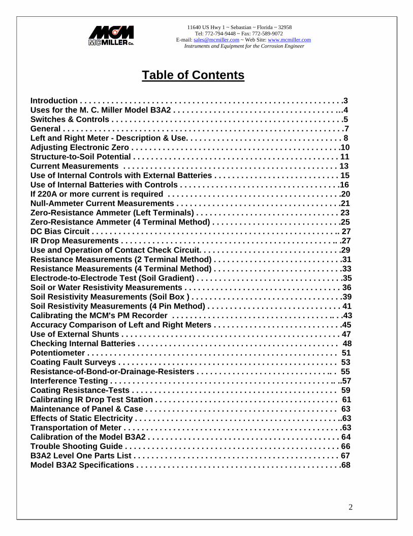
Table of Contents
Introduction . . . . . . . . . . . . . . . . . . . . . . . . . . . . . . . . . . . . . . . . . . . . . . . . . . . . . . . . . . .3 Uses for the M. C. Miller Model B3A2 . . . . . . . . . . . . . . . . . . . . . . . . . . . . . . . . . . . . …4 Switches & Controls . . . . . . . . . . . . . . . . . . . . . . . . . . . . . . . . . . . . . . . . . . . . . . . . . . . .5 General . . . . . . . . . . . . . . . . . . . . . . . . . . . . . . . . . . . . . . . . . . . . . . . . . . . . . . . . . . . . . . .7 Left and Right Meter - Description & Use. . . . . . . . . . . . . . . . . . . . . . . . . . . . . . . . . . . 8 Adjusting Electronic Zero . . . . . . . . . . . . . . . . . . . . . . . . . . . . . . . . . . . . . . . . . . . . . . .10 Structure-to-Soil Potential . . . . . . . . . . . . . . . . . . . . . . . . . . . . . . . . . . . . . . . . . . . . . . 11 Current Measurements . . . . . . . . . . . . . . . . . . . . . . . . . . . . . . . . . . . . . . . . . . . . . . . . 13 Use of Internal Controls with External Batteries . . . . . . . . . . . . . . . . . . . . . . . . . . . . 15 Use of Internal Batteries with Controls . . . . . . . . . . . . . . . . . . . . . . . . . . . . . . . . . . . .16 If 220A or more current is required . . . . . . . . . . . . . . . . . . . . . . . . . . . . . . . . . . . . . . .20 Null-Ammeter Current Measurements . . . . . . . . . . . . . . . . . . . . . . . . . . . . . . . . . . . . .21 Zero-Resistance Ammeter (Left Terminals) . . . . . . . . . . . . . . . . . . . . . . . . . . . . . . . . 23 Zero-Resistance Ammeter (4 Terminal Method) . . . . . . . . . . . . . . . . . . . . . . . . . . . . .25 DC Bias Circuit . . . . . . . . . . . . . . . . . . . . . . . . . . . . . . . . . . . . . . . . . . . . . . . . . . . . . . .. 27 IR Drop Measurements . . . . . . . . . . . . . . . . . . . . . . . . . . . . . . . . . . . . . . . . . . . . . . . .. .27 Use and Operation of Contact Check Circuit. . . . . . . . . . . . . . . . . . . . . . . . . . . . . . . .29 Resistance Measurements (2 Terminal Method) . . . . . . . . . . . . . . . . . . . . . . . . . . . . .31 Resistance Measurements (4 Terminal Method) . . . . . . . . . . . . . . . . . . . . . . . . . . . . .33 Electrode-to-Electrode Test (Soil Gradient) . . . . . . . . . . . . . . . . . . . . . . . . . . . . . . . . .35 Soil or Water Resistivity Measurements . . . . . . . . . . . . . . . . . . . . . . . . . . . . . . . . . . . 36 Soil Resistivity Measurements (Soil Box ) . . . . . . . . . . . . . . . . . . . . . . . . . . . . . . . . . .39 Soil Resistivity Measurements (4 Pin Method) . . . . . . . . . . . . . . . . . . . . . . . . . . . . . . 41 Calibrating the MCM's PM Recorder . . . . . . . . . . . . . . . . . . . . . . . . . . . . . . . . . . . .. . .43 Accuracy Comparison of Left and Right Meters . . . . . . . . . . . . . . . . . . . . . . . . . . . . .45 Use of External Shunts . . . . . . . . . . . . . . . . . . . . . . . . . . . . . . . . . . . . . . . . . . . . . . . . . 47 Checking Internal Batteries . . . . . . . . . . . . . . . . . . . . . . . . . . . . . . . . . . . . . . . . . . . . . 48 Potentiometer . . . . . . . . . . . . . . . . . . . . . . . . . . . . . . . . . . . . . . . . . . . . . . . . . . . . . . . . 51 Coating Fault Surveys . . . . . . . . . . . . . . . . . . . . . . . . . . . . . . . . . . . . . . . . . . . . . . . . . 53 Resistance-of-Bond-or-Drainage-Resisters . . . . . . . . . . . . . . . . . . . . . . . . . . . . . .. . 55 Interference Testing . . . . . . . . . . . . . . . . . . . . . . . . . . . . . . . . . . . . . . . . . . . . . . . . . .. ..57 Coating Resistance-Tests . . . . . . . . . . . . . . . . . . . . . . . . . . . . . . . . . . . . . . . . . . . . . . 59 Calibrating IR Drop Test Station . . . . . . . . . . . . . . . . . . . . . . . . . . . . . . . . . . . . . . . . . 61 Maintenance of Panel & Case . . . . . . . . . . . . . . . . . . . . . . . . . . . . . . . . . . . . . . . . . . . 63 Effects of Static Electricity . . . . . . . . . . . . . . . . . . . . . . . . . . . . . . . . . . . . . . . . . . . . . ..63 Transportation of Meter . . . . . . . . . . . . . . . . . . . . . . . . . . . . . . . . . . . . . . . . . . . . . . . . .63 Calibration of the Model B3A2 . . . . . . . . . . . . . . . . . . . . . . . . . . . . . . . . . . . . . . . . . . . 64 Trouble Shooting Guide . . . . . . . . . . . . . . . . . . . . . . . . . . . . . . . . . . . . . . . . . . . . . . . . 66 B3A2 Level One Parts List . . . . . . . . . . . . . . . . . . . . . . . . . . . . . . . . . . . . . . . . . . . . . . 67 Model B3A2 Specifications . . . . . . . . . . . . . . . . . . . . . . . . . . . . . . . . . . . . . . . . . . . . . .68

11640 US Hwy 1 ~ Sebastian ~ Florida ~ 32958
Tel: 772-794-9448 ~ Fax: 772-589-9072 E-mail: [email protected] ~ Web Site: www.mcmiller.com
Instruments and Equipment for the Corrosion Engineer
3
Introduction
This manual covers the use, operation and maintenance of the B3A2. The new panel introduced with the B3A2 meter was designed to aid the operator in using and understanding this instrument. The following conventions were adopted to help simplify operation of the meter:
Red markings indicate potential (volts) ranges or functions.
Black markings indicate current (amps) ranges or functions.
Green markings indicate resistance (ohms) ranges or functions.
Switches or controls used in conjunction with each other have been connected with lines or enclosed within boxes where possible or practical.
Small colored dots have been included on the panel as position indicators to simplify battery testing procedures.
In those cases where a switch or control can be utilized for more than one function (i.e., amps and volts) it has been color coded to reflect its primary function.
IMPORTANT This manual is primarily intended for use with Model B3A2 meters. It also applies (with slight changes) to Model B3Al meters starting with serial number 3013. The main difference in operation between the B3Al and B3A2 is in the bias circuit. Due to the electrical re-Iocation of the Right-hand meter polarity switch in the B3A2, both positive and negative full scale bias may now be applied. The enhanced versatility of this circuit is further described on page 27 and should be taken into account when using Figures 1 through 24 in the back of this manual.

11640 US Hwy 1 ~ Sebastian ~ Florida ~ 32958
Tel: 772-794-9448 ~ Fax: 772-589-9072 E-mail: [email protected] ~ Web Site: www.mcmiller.com
Instruments and Equipment for the Corrosion Engineer
4
1) Uses for the M.C. Miller Model B3A2
• Structure-to-Soil Potentials.
• Current measurements (direct method).
• Current measurements (null-amp method).
• Current measurements (2 or 4 terminal zero resistance method).
• IR drops.
• Calibration of IR drop Test Stations.
• Resistance (2 or 4 terminal method).
• Soil or Water Resistivity by Soil Box method.
• Soil Resistivity by 4 electrode method.
• Soil potential gradients.
• Continuity tests.
• Pipe coating resistance tests.
• Pipe coating Fault Survey (over-the-ground method).
• Galvanic Anode tests.
• Rectifier Output tests.
• Cathodic Protection Interference tests.
• Cathodic Protection test.
• Duct Slug Survey on lead-covered cables.
• Concrete Bridge Deck survey.
• pH determination.
• Grounding tests.
• Calibration of other meters.
• Temperature measurements using thermocouples.
NOTE: Auxiliary equipment such as reference electrodes, test leads, external battery or temporary ground bed required in most cases.
11640 US Hwy 1 ~ Sebastian ~ Florida ~ 32958
Tel: 772-794-9448 ~ Fax: 772-589-9072 E-mail: [email protected] ~ Web Site: www.mcmiller.com
Instruments and Equipment for the Corrosion Engineer
5
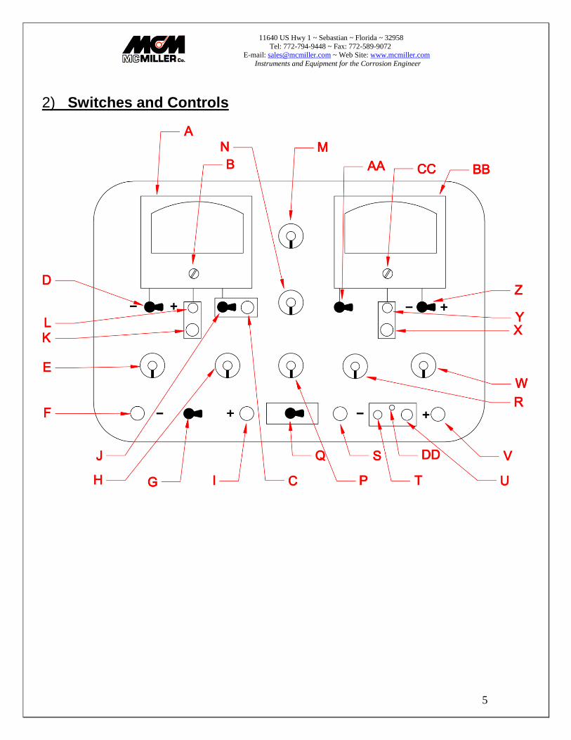
2) Switches and Controls

11640 US Hwy 1 ~ Sebastian ~ Florida ~ 32958
Tel: 772-794-9448 ~ Fax: 772-589-9072 E-mail: [email protected] ~ Web Site: www.mcmiller.com
Instruments and Equipment for the Corrosion Engineer
6
A. Left-hand meter.
B. Mechanical Zero adjust for Left-hand meter.
C. Adjust Control for Contact Check circuit.
D. Polarity Switch for Left-hand meter.
E. Ammeter Range Switch.
F. Negative Terminal for Left-hand meter.
G. Amps Toggle Switch.
H. Voltmeter Range Switch - Left-hand meter.
I. Positive Terminal for Left-hand meter.
J. On/Normal Toggle Switch for Contact Check Circuit.
K. Zero Adjust Push-Button for Left-hand meter.
L. Electronic Zero Adjust Control for Left-hand meter.
M. Coarse Control.
N. Fine Control
P. Rheostat.
Q. Battery Toggle Switch.
R. Range Switch for Right-hand meter.
S. Negative Terminal for Right-hand meter.
T. Bias On/Off Switch.
U. Bias Adjust Control.
V. Positive Terminal for Right-hand meter.
W. Input Resistance Switch for Right-hand meter.
X. Zero Adjust Push-Button for Right-hand meter.
Y. Electronic Zero Adjust for Right-hand meter.
Z. Polarity Switch for Right-hand meter.
AA. To Left Term/Norm Toggle Switch.
BB. Right-hand meter.
CC. Mechanical Zero Adjust for Right-hand meter.
DD. Bias Warning Light.

11640 US Hwy 1 ~ Sebastian ~ Florida ~ 32958
Tel: 772-794-9448 ~ Fax: 772-589-9072 E-mail: [email protected] ~ Web Site: www.mcmiller.com
Instruments and Equipment for the Corrosion Engineer
7
3) General The Model B3A2 is a "fourth generation" version of the Model B3, which has become an industry standard for the Engineer/Technician in testing and design of cathodic protection systems. Improvements incorporated in the B3A2 include active and passive filtering to eliminate electro-magnetic and radio frequency interference, as well as: • Laboratory grade, stable, low noise DC amplifiers. • Meter response time increased 100% without overshoot. • More versatile DC bias circuit. • Reduction of switch contact resistance for internal shunts. • Elimination of nine 1.5 volt "AA" cells replaced by two 9V transistor batteries In this manual, we have included diagrams showing typical external connections for all of the commonly performed corrosion and cathodic protection tests. Also shown are typical positions of various meter controls and switches for these tests. When the B3A2 is not actually in use, all pointed knobs should be pointing straight down and toggle switches should be in the "off' or "normal" position. This will conserve batteries and prevent accidental overload of metering circuits. The connections and switch positions outlined herein are only suggestions and may not apply in all situations or where the practice of some organizations may differ from that of the M. C. Miller Co. For example, some organizations connect the reference electrode to the negative terminal and use the polarity switch to produce upscale readings. Before attempting field tests, it is recommended that the meter operator familiarize himself with applicable D.O.T. regulations. Attendance at one or more of the corrosion control courses sponsored by the National Association of Corrosion Engineers ( N A C E ) is also recommended. If there are any questions regarding any of the following material, we suggest that your contact the M.C. Miller Co., Inc. for clarification.

11640 US Hwy 1 ~ Sebastian ~ Florida ~ 32958
Tel: 772-794-9448 ~ Fax: 772-589-9072 E-mail: [email protected] ~ Web Site: www.mcmiller.com
Instruments and Equipment for the Corrosion Engineer
8
4) Left and Right Meter Description and Use The left-hand meter incorporates the following ranges:
Ammeter ranges: F.S. Voltage Drop Shunt Burden
2 mA 2 mV 1 mV/mA
10 mA 10 mV 1 mV/mA
20 mA 20 mV 1 mV/mA
0.1 A 2 mV 1 mV/50mA
0.2 A 4 mV 1 mV/50mA
1.0 A 20 mV 1 mV/50mA
2.0 A 2 mV 1 mV/1A
10.0 A 10 mV 1 mV/1A
20.0 A 20 mV 1 mV/1A
Voltage ranges:
2 mV 10,000 ohms input resistance
10 mV 10,000 ohms input resistance
20 mV 10 megohms input resistance
0.1 V 10 megohms input resistance
0.2 V 10 megohms input resistance
1.0 V 10 megohms input resistance
2.0 V 10 megohms input resistance
10 V 10 megohms input resistance
100 V 10 megohms input resistance

11640 US Hwy 1 ~ Sebastian ~ Florida ~ 32958
Tel: 772-794-9448 ~ Fax: 772-589-9072 E-mail: [email protected] ~ Web Site: www.mcmiller.com
Instruments and Equipment for the Corrosion Engineer
9
The left hand meter commonly performed tests:
• Rectifier or solar cell output current. • Anode output current • Bond or drainage current. • IR drop on pipe, cable or other metallic structure. • Structure-to-earth potential (2 0mV range and up). • Anode-to-structure potential. • Rectifier or solar cell output voltage. • Potential across insulating flange. • Electrode-to-electrode potential (2 0mV range and up). The right-hand meter incorporates the following ranges:
Voltage ranges:
2 mV 100,000 ohms input resistance
10 mV 100,000 ohms input resistance
20 mV Selectable : 1 thru 200 megohms
0.1 V Selectable : 1 thru 200 megohms
0.2 V Selectable : 1 thru 200 megohms
1.0 V Selectable : 1 thru 200 megohms
2.0 V Selectable : 1 thru 200 megohms
10 V Selectable : 1 thru 200 megohms
20 V Selectable : 1 thru 200 megohms
The right hand meter commonly performed tests:
• Structure-to-earth potential • IR drop on pipe, cable or other metallic structure. • Structure-to-structure potential • Output voltage of rectifier or solar cell • Potential across insulating flange • Electrode-to-electrode potential

11640 US Hwy 1 ~ Sebastian ~ Florida ~ 32958
Tel: 772-794-9448 ~ Fax: 772-589-9072 E-mail: [email protected] ~ Web Site: www.mcmiller.com
Instruments and Equipment for the Corrosion Engineer
10
The left hand and right hand meters can be used in conjunction with each other for the following types of tests: • Resistivity of soil or water samples in Soil Box. • Resistivity of soil by Wenner four-electrode method • Resistance of bond wires, test leads, etc. • Current requirement tests • Coating evaluation tests • Zero resistance ammeter tests • Diode characteristic curves • Null ammeter tests A Contact Check Circuit is provided to check continuity and contact resistance when measuring IR drops. An adjustable DC Bias can be switched into the circuit at any time on all ranges. This facilitates measurement of changes in potential and permits unwanted galvanic potentials to be bucked out when measuring Delta V or soil resistivity
5) Adjusting Electronic Zero When using any range of either the left -hand or right-hand meter, it will be necessary to check and adjust the electronic zero periodically, especially during the first few minutes of operation. This can be quickly accomplished by depressing the zero push button and adjusting the zero adjust knob until the pointer reads zero. It is not necessary to remove test leads while checking and adjusting zero. When the instrument is zeroed on the lowest range (most accurate for zeroing) all the higher ranges will be zeroed.

11640 US Hwy 1 ~ Sebastian ~ Florida ~ 32958
Tel: 772-794-9448 ~ Fax: 772-589-9072 E-mail: [email protected] ~ Web Site: www.mcmiller.com
Instruments and Equipment for the Corrosion Engineer
11
Structure to Soil Potential Fig #1 F
11640 US Hwy 1 ~ Sebastian ~ Florida ~ 32958
Tel: 772-794-9448 ~ Fax: 772-589-9072 E-mail: [email protected] ~ Web Site: www.mcmiller.com
Instruments and Equipment for the Corrosion Engineer
12
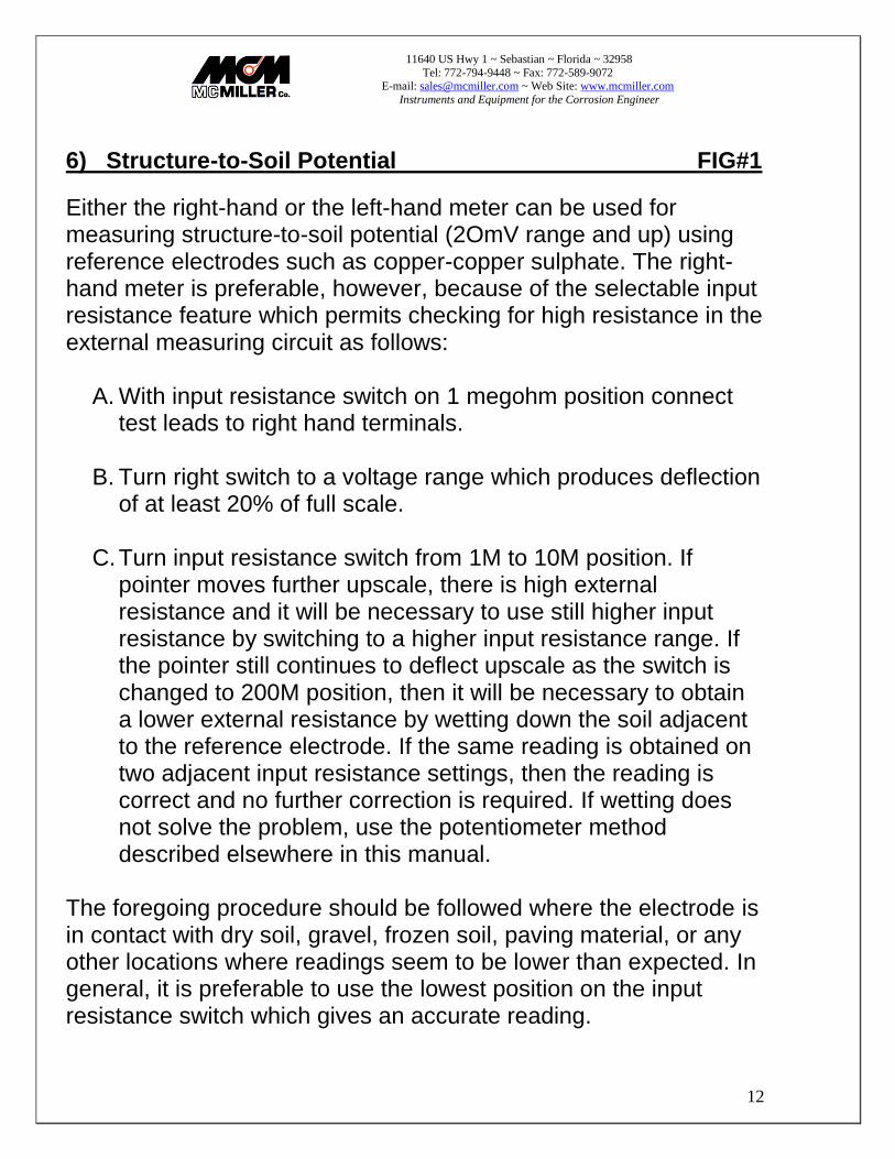
6) Structure-to-Soil Potential FIG#1
Either the right-hand or the left-hand meter can be used for measuring structure-to-soil potential (2OmV range and up) using reference electrodes such as copper-copper sulphate. The right-hand meter is preferable, however, because of the selectable input resistance feature which permits checking for high resistance in the external measuring circuit as follows:
A. With input resistance switch on 1 megohm position connect test leads to right hand terminals.
B. Turn right switch to a voltage range which produces deflection
of at least 20% of full scale.
C. Turn input resistance switch from 1M to 10M position. If pointer moves further upscale, there is high external resistance and it will be necessary to use still higher input resistance by switching to a higher input resistance range. If the pointer still continues to deflect upscale as the switch is changed to 200M position, then it will be necessary to obtain a lower external resistance by wetting down the soil adjacent to the reference electrode. If the same reading is obtained on two adjacent input resistance settings, then the reading is correct and no further correction is required. If wetting does not solve the problem, use the potentiometer method described elsewhere in this manual.
The foregoing procedure should be followed where the electrode is in contact with dry soil, gravel, frozen soil, paving material, or any other locations where readings seem to be lower than expected. In general, it is preferable to use the lowest position on the input resistance switch which gives an accurate reading.
11640 US Hwy 1 ~ Sebastian ~ Florida ~ 32958
Tel: 772-794-9448 ~ Fax: 772-589-9072 E-mail: [email protected] ~ Web Site: www.mcmiller.com
Instruments and Equipment for the Corrosion Engineer
13
Current Measurements Fig #2
11640 US Hwy 1 ~ Sebastian ~ Florida ~ 32958
Tel: 772-794-9448 ~ Fax: 772-589-9072 E-mail: [email protected] ~ Web Site: www.mcmiller.com
Instruments and Equipment for the Corrosion Engineer
14
.
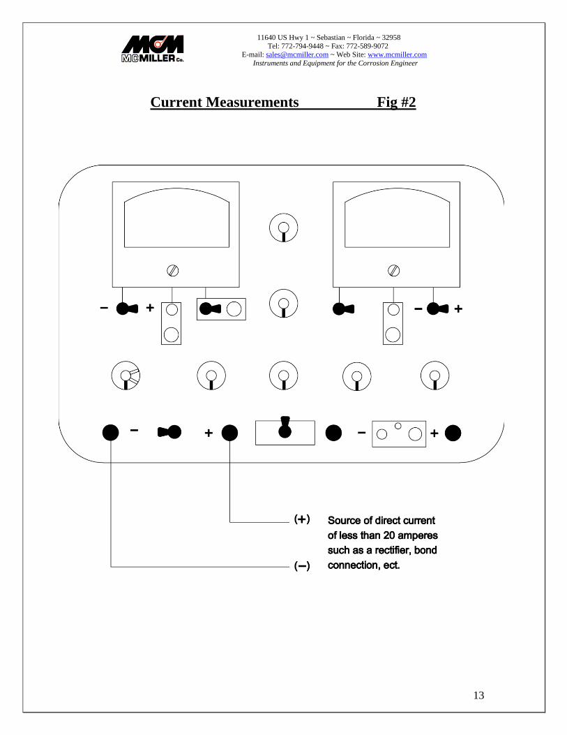
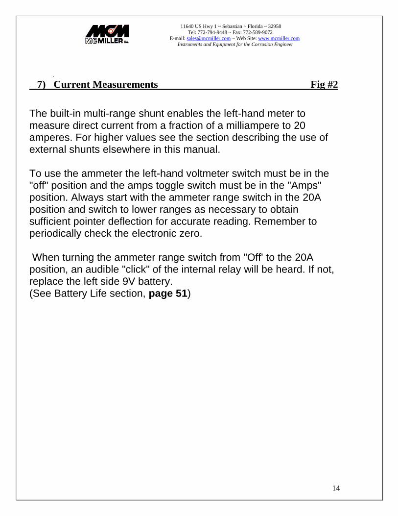
7) Current Measurements Fig #2
The built-in multi-range shunt enables the left-hand meter to measure direct current from a fraction of a milliampere to 20 amperes. For higher values see the section describing the use of external shunts elsewhere in this manual. To use the ammeter the left-hand voltmeter switch must be in the "off" position and the amps toggle switch must be in the "Amps" position. Always start with the ammeter range switch in the 20A position and switch to lower ranges as necessary to obtain sufficient pointer deflection for accurate reading. Remember to periodically check the electronic zero. When turning the ammeter range switch from "Off' to the 20A position, an audible "click" of the internal relay will be heard. If not, replace the left side 9V battery. (See Battery Life section, page 51)

11640 US Hwy 1 ~ Sebastian ~ Florida ~ 32958
Tel: 772-794-9448 ~ Fax: 772-589-9072 E-mail: [email protected] ~ Web Site: www.mcmiller.com
Instruments and Equipment for the Corrosion Engineer
15
Use of Internal Controls with External Batteries Fig #3

11640 US Hwy 1 ~ Sebastian ~ Florida ~ 32958
Tel: 772-794-9448 ~ Fax: 772-589-9072 E-mail: [email protected] ~ Web Site: www.mcmiller.com
Instruments and Equipment for the Corrosion Engineer
16
8) Use of Internal Controls with External Batteries Fig #3
When using and measuring direct current from an external source such as a dry cell, automobile battery, galvanic anode, bond cable, small rectifier, solar cell, etc., the fine and coarse controls and the rheostat can be cut into the circuit to reduce or control the magnitude of the current. This is accomplished by putting the amps toggle switch in the "Amps with Controls" position. To avoid overloading and overheating the controls, the rheostat and controls must be used in the proper sequence if the current is over 220mA. The proper operating sequence is as follows:
A. Turn fine, coarse and rheostat controls to fully counter-clockwise.
B. Connect test leads to left-hand meter terminals.
C. Amps toggle switch to "Amps with Controls" position.
D. Ammeter range switch to 20A position. If current exceeds 15amps the current is too large to handle safely by this method.
E. If the current is 15 amperes or less turn the rheostat control until
the current has been reduced to less than 7 amperes, which is the continuous ampere rating for this control.
F. If the full clockwise position of the rheostat does not reduce
current to the desired value, turn the fine control clockwise until the desired value is reached. This control is rated at 1.3 amperes, but can be safely overloaded for a few seconds.
If this sequence is followed, there should be no problems with these controls.

11640 US Hwy 1 ~ Sebastian ~ Florida ~ 32958
Tel: 772-794-9448 ~ Fax: 772-589-9072 E-mail: [email protected] ~ Web Site: www.mcmiller.com
Instruments and Equipment for the Corrosion Engineer
17
Notes:
_________________________________________________________________
_________________________________________________________________
_________________________________________________________________
_________________________________________________________________
_________________________________________________________________
_________________________________________________________________
_________________________________________________________________
_________________________________________________________________
_________________________________________________________________
_________________________________________________________________
_________________________________________________________________
_________________________________________________________________
_________________________________________________________________
_________________________________________________________________
_________________________________________________________________
_________________________________________________________________
_________________________________________________________________
_________________________________________________________________
_________________________________________________________________
_________________________________________________________________
_________________________________________________________________
_________________________________________________________________
_________________________________________________________________
_________________________________________________________________
_________________________________________________________________
_________________________________________________________________
_________________________________________________________________
_________________________________________________________________
_________________________________________________________________
_________________________________________________________________
_________________________________________________________________
_________________________________________________________________
_________________________________________________________________
_________________________________________________________________
_________________________________________________________________
11640 US Hwy 1 ~ Sebastian ~ Florida ~ 32958
Tel: 772-794-9448 ~ Fax: 772-589-9072 E-mail: [email protected] ~ Web Site: www.mcmiller.com
Instruments and Equipment for the Corrosion Engineer
18
9) Use of Internal Batteries with Control
The internal batteries may be used in series with an external source of the direct current either to increase or decrease the current. The internal batteries with controls can be connected in series with a galvanic anode connected to a structure to increase current output (possibly to determine the amount of current needed to provide protection). The external batteries can be connected in series, but bucking the external current flow, to reduce the magnitude of the current and in some cases to even reverse the direction of flow. Also, internal batteries with controls can be used (without any external DC source) to supply test current from a few milliamperes to about two amperes (or slightly more for a few seconds testing). The magnitude of the current supplied from internal batteries can be adjusted with the fine, coarse and rheostat controls, and can be switched on and off for testing by using the amps toggle switch or the battery toggle switch (depending on whether it is desired to completely open the current circuit or merely to disconnect the batteries, leaving the current circuit closed through the shunt and controls circuit). When supplying test current from the internal batteries, it is essential that the sequence of use of the rheostat, fine and coarse controls be carefully followed to avoid overloading and overheating the controls.
11640 US Hwy 1 ~ Sebastian ~ Florida ~ 32958
Tel: 772-794-9448 ~ Fax: 772-589-9072 E-mail: [email protected] ~ Web Site: www.mcmiller.com
Instruments and Equipment for the Corrosion Engineer
19
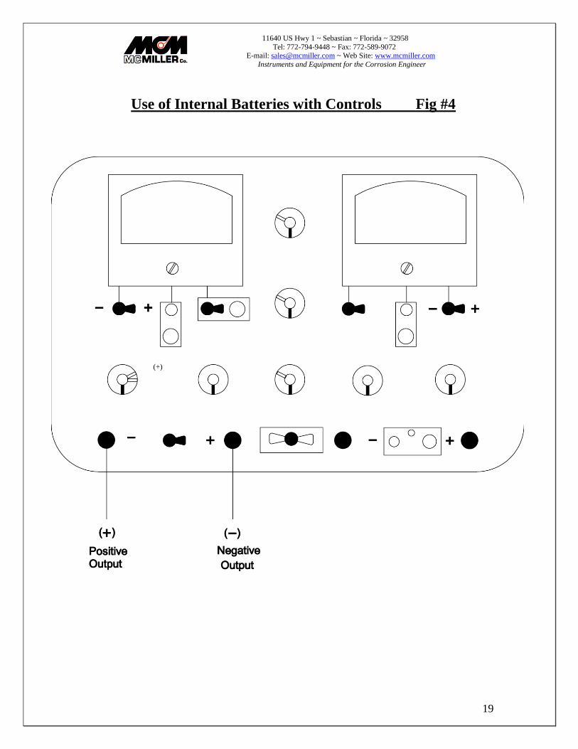
Use of Internal Batteries with Controls Fig #4
(+)

11640 US Hwy 1 ~ Sebastian ~ Florida ~ 32958
Tel: 772-794-9448 ~ Fax: 772-589-9072 E-mail: [email protected] ~ Web Site: www.mcmiller.com
Instruments and Equipment for the Corrosion Engineer
20
Use of Internal Batteries with Controls Fig #4
1. (Counter-clockwise) or "Off" position. 2. Connect test leads of the circuit to be tested. 3. Turn amps range switch to ampere or milliampere range desired depending
upon value of the current required for testing. 4. Left-hand meter polarity switch to the (+) position. 5. Amps toggle switch to "Amps with Controls" position. Battery toggle switch
to "1.5V' or "3V' position, depending upon circuit resistance and value of current desired.
If only a few milliamperes are required:
1. Turn fine control slowly. If this does not provide sufficient current return the control to its normal position, and
2. Turn the coarse control slowly and watch the ammeter. Continue to turn the control until the ammeter indicates slightly less than the desired current, then
3. Make the final adjustment with the fine control.
If 220mA or more current is required:
1. Turn the coarse control slowly until the ammeter indicates slightly less than the desired current.
2. Turn the fine control until the desired current is reached. 3. If turning the coarse control to the maximum clockwise position does not
provide sufficient current, leave the coarse control in the maximum position (fully clockwise) and then turn the fine control. Turn the fine control to provide slightly more current than is desired, then turn the rheostat clockwise (which increases the resistance in the circuit) to reduce the current to the desired value. Note that the rheostat is normally left in the counter-clockwise position, resulting in minimum resistance.
4. lest current can be turned on and off with the amps toggle switch and the effects of the test current can be measured on the right hand meter if desired
11640 US Hwy 1 ~ Sebastian ~ Florida ~ 32958
Tel: 772-794-9448 ~ Fax: 772-589-9072 E-mail: [email protected] ~ Web Site: www.mcmiller.com
Instruments and Equipment for the Corrosion Engineer
21
Null Ammeter Current Measurements Fig #5
11640 US Hwy 1 ~ Sebastian ~ Florida ~ 32958
Tel: 772-794-9448 ~ Fax: 772-589-9072 E-mail: [email protected] ~ Web Site: www.mcmiller.com
Instruments and Equipment for the Corrosion Engineer
22
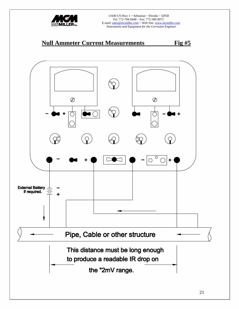
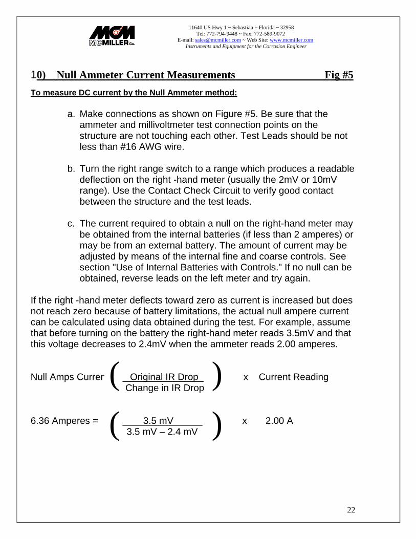
10) Null Ammeter Current Measurements Fig #5
To measure DC current by the Null Ammeter method:
a. Make connections as shown on Figure #5. Be sure that the
ammeter and millivoltmeter test connection points on the structure are not touching each other. Test Leads should be not less than #16 AWG wire.
b. Turn the right range switch to a range which produces a readable
deflection on the right -hand meter (usually the 2mV or 10mV range). Use the Contact Check Circuit to verify good contact between the structure and the test leads.
c. The current required to obtain a null on the right-hand meter may
be obtained from the internal batteries (if less than 2 amperes) or may be from an external battery. The amount of current may be adjusted by means of the internal fine and coarse controls. See section "Use of Internal Batteries with Controls." If no null can be obtained, reverse leads on the left meter and try again.
If the right -hand meter deflects toward zero as current is increased but does not reach zero because of battery limitations, the actual null ampere current can be calculated using data obtained during the test. For example, assume that before turning on the battery the right-hand meter reads 3.5mV and that this voltage decreases to 2.4mV when the ammeter reads 2.00 amperes. Null Amps Current = Original IR Drop x Current Reading Change in IR Drop 6.36 Amperes = 3.5 mV x 2.00 A 3.5 mV – 2.4 mV
)
) (
(

11640 US Hwy 1 ~ Sebastian ~ Florida ~ 32958
Tel: 772-794-9448 ~ Fax: 772-589-9072 E-mail: [email protected] ~ Web Site: www.mcmiller.com
Instruments and Equipment for the Corrosion Engineer
23
Zero Resistance Ammeter (Left Terminals) Fig #6

11640 US Hwy 1 ~ Sebastian ~ Florida ~ 32958
Tel: 772-794-9448 ~ Fax: 772-589-9072 E-mail: [email protected] ~ Web Site: www.mcmiller.com
Instruments and Equipment for the Corrosion Engineer
24
11) Zero Resistance Ammeter (Left Terminals) Fig #6
In certain circuits where open circuit voltage is less than about 500mV, the insertion of an ammeter with 20mV IR drop could cause considerable error. For example, a zinc anode installation connected to a polarized structure might have an open circuit voltage of less than 200mV. The zero-resistance ammeter circuit eliminates IR drop within the meter. A zero-resistance type milliammeter/ammeter circuit is built into the B3A2. The circuit is set up with the "To Left Term/Norm" toggle switch in the "To Left Turn" position. With the left meter being used to measure the current, the amps toggle switch is thrown to the "Amps With Controls" position and the battery toggle switch to the "1.5V" or "3V' position. The current is then "pumped" through the circuit and ammeter by using the batteries, controls and rheostat until the right-hand meter (which is connected across the left terminals) is adjusted to zero. The right range switch should be in the "2mV', "10mV" or "20mV' position for the most accurate results. The ammeter shunt, internal wiring, etc., now appear to have zero resistance in the circuit. The zero-resistance ammeter circuit can be used for measurements from a few milliamperes to about 2 amperes. This circuit is somewhat "tricky" to use in that as the coarse and fine controls are turned the current flow is first reduced then increased to the original value and then increased further until the right-hand meter reads zero. Use caution at first until the action is understood. When making zero-resistance measurements, the positive lead of the current source must be connected to the positive terminal of the left meter.
11640 US Hwy 1 ~ Sebastian ~ Florida ~ 32958
Tel: 772-794-9448 ~ Fax: 772-589-9072 E-mail: [email protected] ~ Web Site: www.mcmiller.com
Instruments and Equipment for the Corrosion Engineer
25
Zero Resistance Ammeter (4 Terminal Method) Fig #7

11640 US Hwy 1 ~ Sebastian ~ Florida ~ 32958
Tel: 772-794-9448 ~ Fax: 772-589-9072 E-mail: [email protected] ~ Web Site: www.mcmiller.com
Instruments and Equipment for the Corrosion Engineer
26
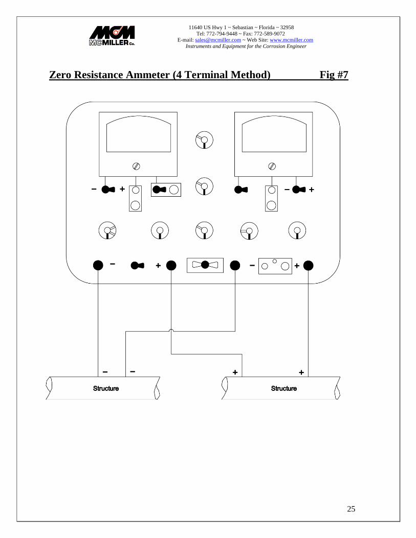
12) Zero Resistance Ammeter (4 Terminal Method) Fig #7
Zero-resistance current measurements can also be made with the "To Left Term/Norm" toggle switch in the "Norm" position, in which case the effects of both the ammeter and lead resistances can be completely nullified. Four test leads are required, but otherwise the procedure is the same as described in the section "Zero-Resistance Ammeter (Left Terminals)." If the right -hand meter deflects toward zero as current is increased but does not reach zero because of battery limitations, the actual zero resistance current can be calculated using data obtained during the test. For example, assume that before commencing the test the open circuit voltage is 350mV and that the voltage between the two structures decreases to 240mV when the ammeter reads 2.00A.
Zero-Resistance Current = Open Circuit Voltage X Current Reading
Change of Voltage
6.36 Amps = 350 mV____
350 mV-240 mV ( )
( )
11640 US Hwy 1 ~ Sebastian ~ Florida ~ 32958
Tel: 772-794-9448 ~ Fax: 772-589-9072 E-mail: [email protected] ~ Web Site: www.mcmiller.com
Instruments and Equipment for the Corrosion Engineer
27
IR Drop Measurements Fig#8

11640 US Hwy 1 ~ Sebastian ~ Florida ~ 32958
Tel: 772-794-9448 ~ Fax: 772-589-9072 E-mail: [email protected] ~ Web Site: www.mcmiller.com
Instruments and Equipment for the Corrosion Engineer
28
13) DC Bias Circuit
An adjustable, full scale DC bias can be switched into the right-hand meter circuit at any time on any range. When the bias circuit is in use a red pilot light on the panel should glow as a warning signal. The amount of bias can be observed directly on the right -hand meter before test leads are attached. Make sure that the bias circuit is turned off when not in use. The principal use of the bias is to facilitate measurement of changes in potential (Delta V), such as when measuring the change in structure to-soil potential during cathodic protection current requirement tests, measuring resistance of anode, ground bed or structure to remote earth, or measuring soil resistivity by the four- pin (Wenner) method, either in place to various depths, or in the soil box. For these resistivity tests the bias serves to offset the effects of both polarization and residual galvanic potential between potential pins. The bias circuit is also very useful for increasing the resolution of a voltage reading by a factor of 2 or 5, depending on range. An example: For a reading of 350mV, a change of + /- 1mV cannot be discerned. (1V range). The application of full scale negative bias on the .2V range, then taking the measurement, would produce a reading of 150mV. A 1mV change can now be easily resolved in 1/2 division increments.
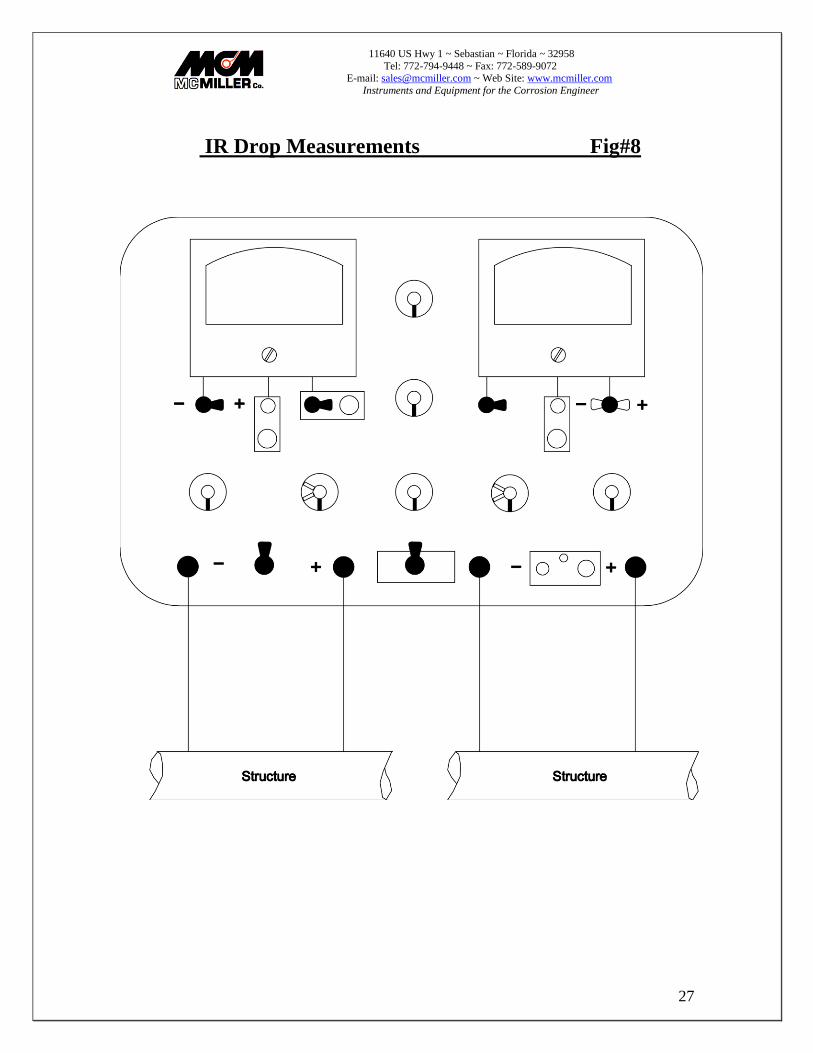
14) IR Drop Measurements Fig #8
Either the left-hand or the right-hand meter can be used to measure voltage drop (IR) on a metallic structure such as a pipe, cable, steel piling, etc. The reading is used in conjunction with known characteristics of the material to calculate magnitude of current flow. Remember to check the electronic zero periodically. Test leads should be kept as short as possible, preferably #16A WG wire or heavier, and connections to the structure must be bright and shiny to insure low contact resistance. V se of the contact check circuit which is built into the left -hand meter circuit is strongly recommended in order to avoid erroneous readings caused by broken wires in test stations or poor contact with the structure. See the section "Use and Operation of Contact Check Circuit." IR drop measurements are normally made on the 2mV or 10mV ranges, where the sensitivity is greatest.

11640 US Hwy 1 ~ Sebastian ~ Florida ~ 32958
Tel: 772-794-9448 ~ Fax: 772-589-9072 E-mail: [email protected] ~ Web Site: www.mcmiller.com
Instruments and Equipment for the Corrosion Engineer
29
Use and Operation of Contact Check Circuit Fig #9

11640 US Hwy 1 ~ Sebastian ~ Florida ~ 32958
Tel: 772-794-9448 ~ Fax: 772-589-9072 E-mail: [email protected] ~ Web Site: www.mcmiller.com
Instruments and Equipment for the Corrosion Engineer
30
15) Use and Operation of Contact Check Circuit Fig #9
The contact check circuit functions and is used like an ohmmeter. To use the circuit:
1. Contact check circuit toggle switch to "on" position. 2. Short together the ends of the test leads being used and
adjust the left-hand meter to full scale using the contact check circuit control. This is the same as adjusting zero on an ohmmeter.
3. Any additional resistance inserted into the circuit after step B above will cause the meter to read less than full scale. When the circuit is not continuous (open), the meter will read zero.
When making contact with cable sheaths, pipes or other structures, the pointer of the left -hand meter will return to full scale when the contacts have practically zero resistance. If the resistance of the two contacts is approximately 1 ohm, the pointer will be at about .85 on the lower scale. When good contacts have been obtained, return the toggle switch to the "Normal" position and proceed to take IR drop readings. If the readings do not "look" right, repeat the contact check, as a slight movement of the contact or probe bars may have introduced resistance.
Typical applications: • Check contacts when probing down to pipe for IR drop test. • Check continuity of test station wiring. • Check for broken test lead. • Check for shorted flange bolt (bolts are insulated at both ends).

11640 US Hwy 1 ~ Sebastian ~ Florida ~ 32958
Tel: 772-794-9448 ~ Fax: 772-589-9072 E-mail: [email protected] ~ Web Site: www.mcmiller.com
Instruments and Equipment for the Corrosion Engineer
31
Resistance measurements (2 Terminal Method) Fig #10
11640 US Hwy 1 ~ Sebastian ~ Florida ~ 32958
Tel: 772-794-9448 ~ Fax: 772-589-9072 E-mail: [email protected] ~ Web Site: www.mcmiller.com
Instruments and Equipment for the Corrosion Engineer
32
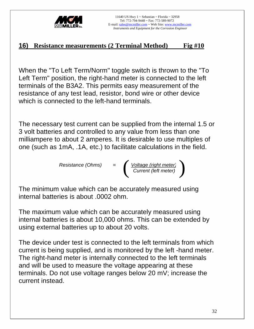
16) Resistance measurements (2 Terminal Method) Fig #10
When the "To Left Term/Norm" toggle switch is thrown to the "To Left Term" position, the right-hand meter is connected to the left terminals of the B3A2. This permits easy measurement of the resistance of any test lead, resistor, bond wire or other device which is connected to the left-hand terminals. The necessary test current can be supplied from the internal 1.5 or 3 volt batteries and controlled to any value from less than one milliampere to about 2 amperes. It is desirable to use multiples of one (such as 1mA, .1A, etc.) to facilitate calculations in the field.
Resistance (Ohms) = Voltage (right meter)
Current (left meter)
The minimum value which can be accurately measured using internal batteries is about .0002 ohm. The maximum value which can be accurately measured using internal batteries is about 10,000 ohms. This can be extended by using external batteries up to about 20 volts. The device under test is connected to the left terminals from which current is being supplied, and is monitored by the left -hand meter. The right-hand meter is internally connected to the left terminals and will be used to measure the voltage appearing at these terminals. Do not use voltage ranges below 20 mV; increase the current instead.
( )
11640 US Hwy 1 ~ Sebastian ~ Florida ~ 32958
Tel: 772-794-9448 ~ Fax: 772-589-9072 E-mail: [email protected] ~ Web Site: www.mcmiller.com
Instruments and Equipment for the Corrosion Engineer
33
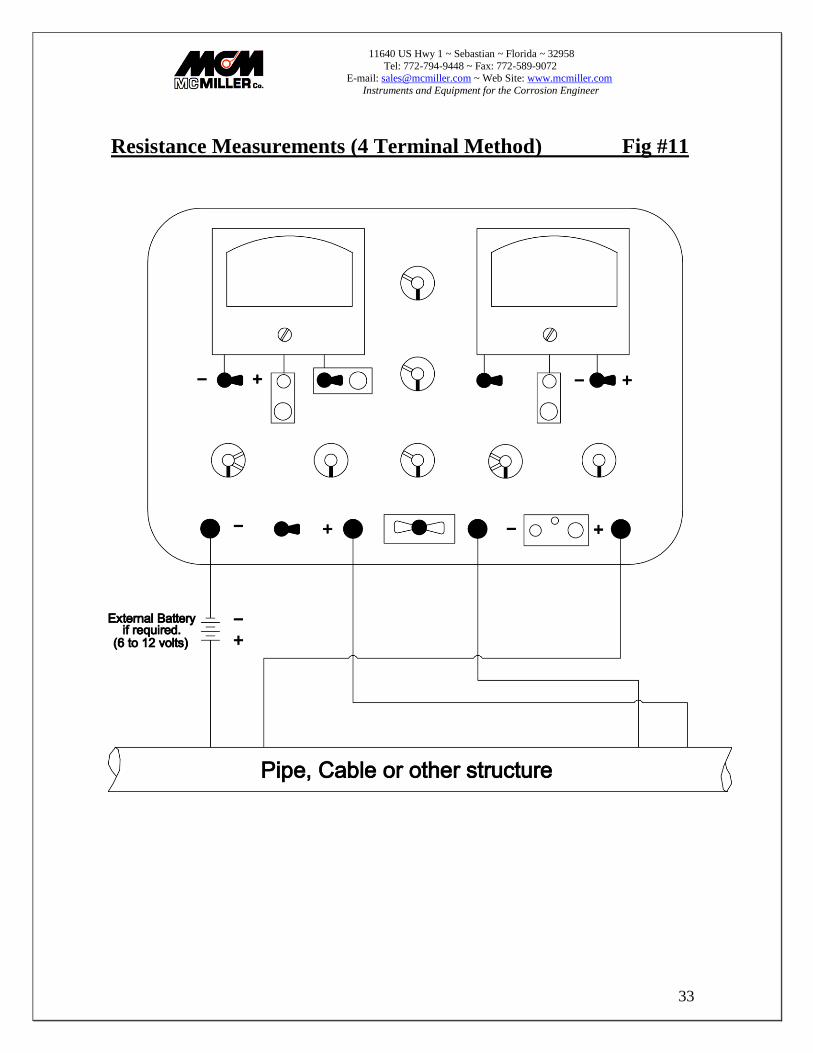
Resistance Measurements (4 Terminal Method) Fig #11
11640 US Hwy 1 ~ Sebastian ~ Florida ~ 32958
Tel: 772-794-9448 ~ Fax: 772-589-9072 E-mail: [email protected] ~ Web Site: www.mcmiller.com
Instruments and Equipment for the Corrosion Engineer
34
17) Resistance Measurements (4 Terminal Method) Fig #11
When the "To Left Term/Norm" toggle switch is in the "Norm" position, the right-hand meter operates from the right terminals. This permits resistance measurement by the four terminal method. This method is employed where the effects of test lead and contact resistance must be eliminated. Typical examples are:
• Calibration of four-lead IR drop test stations on pipe or cable. • Resistance-to-earth of structures such as grounding facilities. • Pipe-to-casing resistance. Except as noted above, the test procedure is the same as for the two terminal method. Care must be taken to make sure test clips from current and potential leads do not touch each other.

11640 US Hwy 1 ~ Sebastian ~ Florida ~ 32958
Tel: 772-794-9448 ~ Fax: 772-589-9072 E-mail: [email protected] ~ Web Site: www.mcmiller.com
Instruments and Equipment for the Corrosion Engineer
35
Electrode to Electrode Test (Soil Gradient) Fig #12

11640 US Hwy 1 ~ Sebastian ~ Florida ~ 32958
Tel: 772-794-9448 ~ Fax: 772-589-9072 E-mail: [email protected] ~ Web Site: www.mcmiller.com
Instruments and Equipment for the Corrosion Engineer
36
18) Electrode to Electrode Test (Soil Gradient) Fig #12
The voltage drop in the earth caused by cathodic protection currents, corrosion currents, or stray DC currents can be easily measured by using two matched copper-sulphate electrodes placed on the surface of the ground at desired spacing (usually between 5' and 100'). The preferred method is to use the right-hand meter as described in the section "Structure-To-Soil Potential", making use of the selectable input resistance feature as necessary. Use only on ranges 20mV and above. When one electrode is placed over the pipe and the other is placed to one side, the measurement is called a "side drain." This type of measurement is frequently used on bare pipe lines to ascertain whether the pipe is picking up or discharging current. The best results are obtained when measurements are taken on both sides of the pipe. If the electrode located over the pipe is negative to the electrode placed a few feet to either side of the line then, the pipe is probably picking up current. If the reverse is true, the pipe is probably discharging current (corroding).
19) Soil or Water Resistivity measurements
The B3A2 can be used to measure resistivity over a very wide range of values, a much wider range than can be covered by any other soil resistivity measuring instrument, by using external batteries or a dynamotor. Connections are shown in Fig. #13 and #14 for the 'Wenner" four-pin method for measuring resistivity of soil in place to various depths, and for samples of soil or water in the soil box. The DC bias circuit is used to facilitate measuring Delta V (change in potential), and the current circuit is opened with the amps toggle switch. The effects of residual galvanic potential between the two potential pins and the polarization of the two potential pins are eliminated by adjusting the right-hand meter to zero with current
11640 US Hwy 1 ~ Sebastian ~ Florida ~ 32958
Tel: 772-794-9448 ~ Fax: 772-589-9072 E-mail: [email protected] ~ Web Site: www.mcmiller.com
Instruments and Equipment for the Corrosion Engineer
37
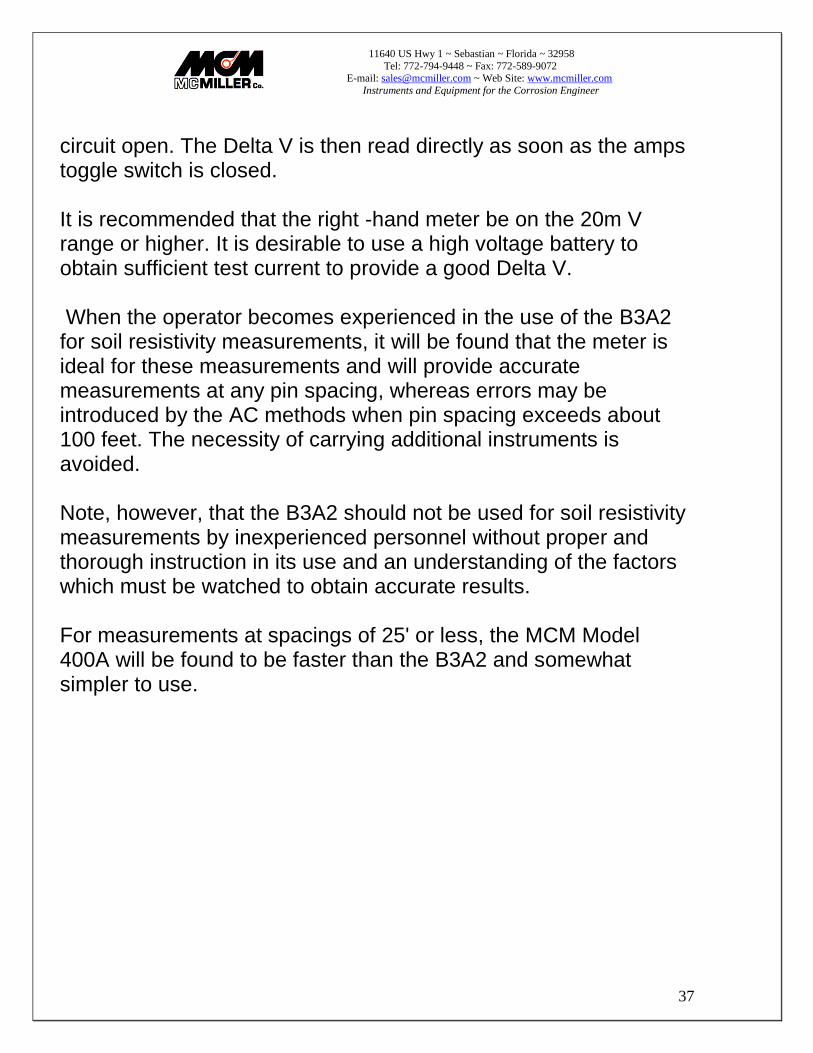
circuit open. The Delta V is then read directly as soon as the amps toggle switch is closed. It is recommended that the right -hand meter be on the 20m V range or higher. It is desirable to use a high voltage battery to obtain sufficient test current to provide a good Delta V. When the operator becomes experienced in the use of the B3A2 for soil resistivity measurements, it will be found that the meter is ideal for these measurements and will provide accurate measurements at any pin spacing, whereas errors may be introduced by the AC methods when pin spacing exceeds about 100 feet. The necessity of carrying additional instruments is avoided. Note, however, that the B3A2 should not be used for soil resistivity measurements by inexperienced personnel without proper and thorough instruction in its use and an understanding of the factors which must be watched to obtain accurate results. For measurements at spacings of 25' or less, the MCM Model 400A will be found to be faster than the B3A2 and somewhat simpler to use.

11640 US Hwy 1 ~ Sebastian ~ Florida ~ 32958
Tel: 772-794-9448 ~ Fax: 772-589-9072 E-mail: [email protected] ~ Web Site: www.mcmiller.com
Instruments and Equipment for the Corrosion Engineer
38
Notes:
______________________________________________________________________________________________________
______________________________________________________________________________________________________
______________________________________________________________________________________________________
______________________________________________________________________________________________________
______________________________________________________________________________________________________
______________________________________________________________________________________________________
______________________________________________________________________________________________________
______________________________________________________________________________________________________
______________________________________________________________________________________________________
______________________________________________________________________________________________________
______________________________________________________________________________________________________
______________________________________________________________________________________________________
______________________________________________________________________________________________________
______________________________________________________________________________________________________
______________________________________________________________________________________________________
______________________________________________________________________________________________________
______________________________________________________________________________________________________
______________________________________________________________________________________________________
______________________________________________________________________________________________________
______________________________________________________________________________________________________
______________________________________________________________________________________________________
______________________________________________________________________________________________________
______________________________________________________________________________________________________
______________________________________________________________________________________________________
______________________________________________________________________________________________________
______________________________________________________________________________________________________
______________________________________________________________________________________________________
______________________________________________________________________________________________________
11640 US Hwy 1 ~ Sebastian ~ Florida ~ 32958
Tel: 772-794-9448 ~ Fax: 772-589-9072 E-mail: [email protected] ~ Web Site: www.mcmiller.com
Instruments and Equipment for the Corrosion Engineer
39
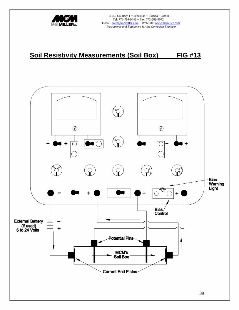
Soil Resistivity Measurements (Soil Box) FIG #13

11640 US Hwy 1 ~ Sebastian ~ Florida ~ 32958
Tel: 772-794-9448 ~ Fax: 772-589-9072 E-mail: [email protected] ~ Web Site: www.mcmiller.com
Instruments and Equipment for the Corrosion Engineer
40
20) Soil Resistivity Measurements (Soil Box) Fig #13
Fill soil box to the rim. Soil samples should be firmly tamped in order to simulate field conditions. Temporary removal of potential pins will facilitate the tamping process. _____ΔV____ Resistivity= Current Where:
ΔV = change in potential which occurs when test current is switched on. This is read on the right-hand meter. (On voltage - Off voltage) Current = reading on the left-hand meter, when the amps toggle switch is thrown to the "Amps with Controls" position. Resistivity is measured in Ohm – Centimeter
) (
11640 US Hwy 1 ~ Sebastian ~ Florida ~ 32958
Tel: 772-794-9448 ~ Fax: 772-589-9072 E-mail: [email protected] ~ Web Site: www.mcmiller.com
Instruments and Equipment for the Corrosion Engineer
41
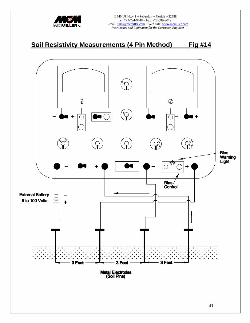
Soil Resistivity Measurements (4 Pin Method) Fig #14
11640 US Hwy 1 ~ Sebastian ~ Florida ~ 32958
Tel: 772-794-9448 ~ Fax: 772-589-9072 E-mail: [email protected] ~ Web Site: www.mcmiller.com
Instruments and Equipment for the Corrosion Engineer
42
21) Soil Resistivity Measurements (4 Pin Method) Fig #14
Resistivity (Ohm-cm) = (191.5 x A) x ___AV____ Current
A = spacing between adjacent pins (in feet) Fig. #14 ΔV = change in potential which occurs when test current is switched on. This is read on the right-hand meter. (On voltage - Off voltage) Current = reading on the left-hand meter, when the amps toggle switch is thrown to the "Amps with Controls" position. Note: For convenience the bias circuit is normally used to zero the reading on the right-hand meter before the amps toggle switch is placed in the "Amps with Controls" position. If ΔV is in volts, current must be in amperes. If Δ V is in millivolts, current must be in milliamperes
) (
11640 US Hwy 1 ~ Sebastian ~ Florida ~ 32958
Tel: 772-794-9448 ~ Fax: 772-589-9072 E-mail: [email protected] ~ Web Site: www.mcmiller.com
Instruments and Equipment for the Corrosion Engineer
43
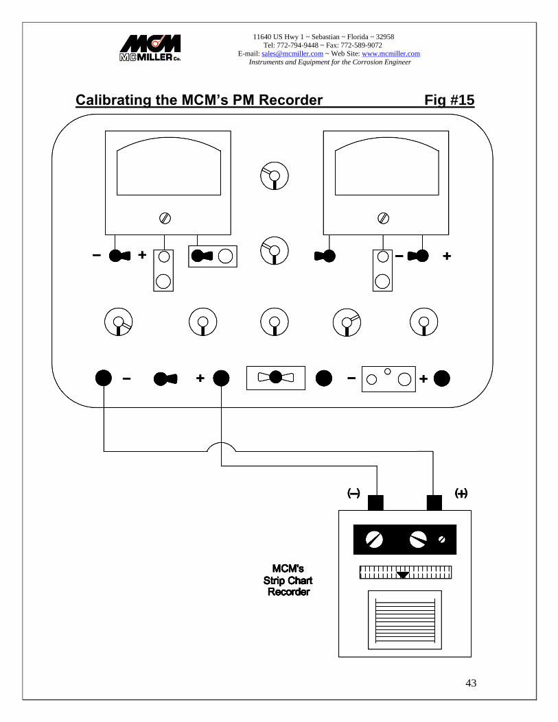
Calibrating the MCM’s PM Recorder Fig #15

11640 US Hwy 1 ~ Sebastian ~ Florida ~ 32958
Tel: 772-794-9448 ~ Fax: 772-589-9072 E-mail: [email protected] ~ Web Site: www.mcmiller.com
Instruments and Equipment for the Corrosion Engineer
44
22) Calibrating the MCM’s PM Recorder Fig #15
The Model B3A2 can be used to provide accurate measured potentials for use in quickly checking and calibrating Model NR-1 Recorder, or other meters, as follows:
A. Connect left terminals of the B3A2 to the Recorder input terminals (- terminal of the left-hand meter to the + terminal of the Recorder)
B. Turn the Recorder function switch to the "Zero" position and adjust to mid
scale zero position as necessary. Turn function switch to "Use" position and Recorder range switch to "1V' position.
C. Turn left voltmeter range switch to "Off' position.
D. Turn ammeter range switch to "20A" range.
E. Throw battery toggle switch to "1.5V' or "3V" position and amps toggle
switch to "Amps with Controls" position.
F. Throw "To Left Term/Norm" toggle switch to "To Left Term" position.
G. Turn right meter range switch to "1V" range.
H. Throw right polarity switch to "-" position.
I. Turn coarse and fine controls until right-hand meter indicates exactly 1volt.
J. Recorder pen should now be at the right end of the scale. Adjust calibrate control (located behind right side of Recorder panel) as necessary to bring pen to right end of scale.
K. Turn Recorder function switch to "Calib" position. Adjust pen to right end of scale using "2.5mV Adj" control (located behind right side of Recorder panel).
Recorder is now calibrated. All ranges should now be accurate within 2% of full scale unless one of the range resistors is defective. Ranges other than 1volt can be checked by adjusting the coarse and fine controls to the desired value (between 0 and 3 volts) and turning the right range switch and the Recorder range switch accordingly.
11640 US Hwy 1 ~ Sebastian ~ Florida ~ 32958
Tel: 772-794-9448 ~ Fax: 772-589-9072 E-mail: [email protected] ~ Web Site: www.mcmiller.com
Instruments and Equipment for the Corrosion Engineer
45
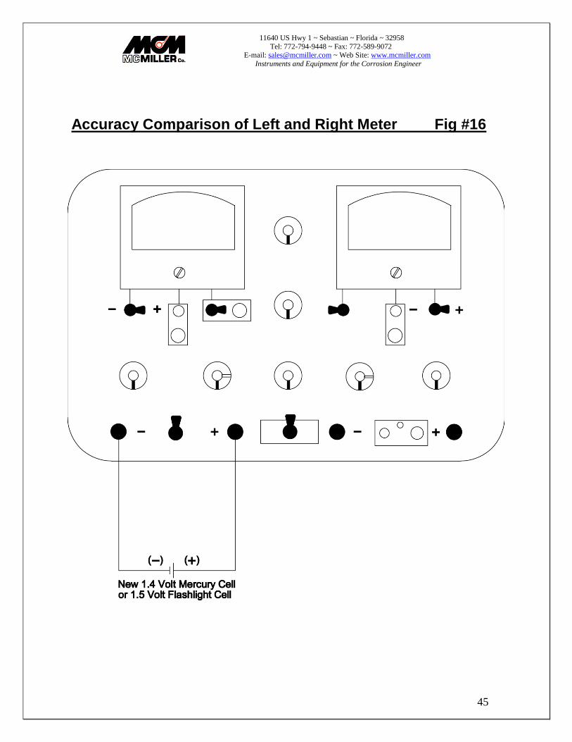
Accuracy Comparison of Left and Right Meter Fig #16
11640 US Hwy 1 ~ Sebastian ~ Florida ~ 32958
Tel: 772-794-9448 ~ Fax: 772-589-9072 E-mail: [email protected] ~ Web Site: www.mcmiller.com
Instruments and Equipment for the Corrosion Engineer
46
23) Accuracy Comparison of Left and Right Meters Fig #16
Sometimes during use the meter is ''banged'' with a sudden overload or the reading "looks" wrong, and the operator may wonder if one of the meters is inaccurate. Meters can be checked by the comparison method as follows:
a. Throw the "To Left Term/Norm" toggle switch to the "To Left Term" position.
b. Turn left and right range switches to the same range, for example, the "2V' range
c. Connect a new flashlight battery to the left terminals.
If both instruments read the same or within one or two divisions it can be assumed that both are within 1-2% accuracy, since the probability of both being damaged or inaccurate to the same degree at the same time is very remote. However, if either the left-hand or right-hand meter is more than 2% high or low, the indication is that one or the other is inaccurate. Normally, the same difference (in percent) between the two instruments will be found on all ranges. Therefore, it can be assumed that the trouble is in the meter itself or in the damping resistor, if used. However, if the difference occurs on only one or two ranges, the trouble probably is in the series range resistor.

11640 US Hwy 1 ~ Sebastian ~ Florida ~ 32958
Tel: 772-794-9448 ~ Fax: 772-589-9072 E-mail: [email protected] ~ Web Site: www.mcmiller.com
Instruments and Equipment for the Corrosion Engineer
47
Use of External Shunts Fig #17

11640 US Hwy 1 ~ Sebastian ~ Florida ~ 32958
Tel: 772-794-9448 ~ Fax: 772-589-9072 E-mail: [email protected] ~ Web Site: www.mcmiller.com
Instruments and Equipment for the Corrosion Engineer
48
24) Use of External Shunts Fig #17
The use of an external shunt, such as MCM’s 100 Ampere Shunt, permits either the right-hand or the left-hand meter to be used as an ammeter. The 100 Ampere Shunt has a resistance of .001 ohm, which means that current flowing through the shunt will produce 1mV drop per ampere. This millivolt drop can be measured by either the left hand or the right-hand meter. The ".1V" range (100 millivolts) will make either instrument serve as a 100 ampere ammeter. When using an external shunt with the left -hand meter, the amps toggle switch must be in the "Volts" (open) position. Use of the lower mV ranges will provide lower ampere ranges. For example, the "2mV " range would yield a 2 ampere range when using the 100 Ampere Shunt. It is permissible to measure up to 200 ampere for a few seconds, using the " .2V” (200 millivolts) range. External shunts must be used if current exceeding 20 amperes is to be measured, or if it is desired to use the righthand meter to measure current.
25) Checking Internal Batteries
All internal batteries should be checked frequently and replaced when necessary to avoid costly damage caused by leaking cells. Remove all batteries when the meter is to be stored for more than a few months. Amplifier Batteries - One 9V transistor battery per amplifier. Place both left and right voltmeter range switches in "Bat" position. Pointers should come to rest in "Bat'y Test" sector. If pointer does not reach "Bat'y Test" sector, replace batteries.
11640 US Hwy 1 ~ Sebastian ~ Florida ~ 32958
Tel: 772-794-9448 ~ Fax: 772-589-9072 E-mail: [email protected] ~ Web Site: www.mcmiller.com
Instruments and Equipment for the Corrosion Engineer
49
Contact Check Circuit - One "AA" Penlight cell.
A. Contact check toggle switch to "On" position. B. Right range switch to "2V" range. C. Right polarity switch to "-" position. D. "To Left Term/Norm" toggle switch to "To Left Term" position. E. Pointer should deflect to at least 1.4 volts.
1.5 & 3 V Internal Batteries- Three “D” cells A. Ammeter range switch to "20A" range. B. Amps toggle switch to "Amps with Controls" position. C. "To Left Term/Norm" toggle switch to "To Left Term" position. D. Right polarity switch to "-" position. E. Right range switch to "10V' range. F. Turn both coarse and fine controls fully clockwise. G. Battery toggle switch to "1.5V' position. H. Right-hand meter should indicate at least 1.4 volts. I. Battery toggle switch to "3V' position. J. Right-hand meter should indicate at least 2.8 volts.
*Note that a colored dot has been marked on the panel at the various switch and control locations as an aid in making battery tests.

11640 US Hwy 1 ~ Sebastian ~ Florida ~ 32958
Tel: 772-794-9448 ~ Fax: 772-589-9072 E-mail: [email protected] ~ Web Site: www.mcmiller.com
Instruments and Equipment for the Corrosion Engineer
50
Battery Life
In general, as energy is extracted from a battery, the internal resistance increases. The term "surface charge" describes this phenomena and it is exhibited as follows: A 9V battery reads 7.5 volts, which is adequate for operation of anamplifier that only requires 1 or 2 milliamps of current. A short term load in excess of 20 milliamps will reduce the 7.5 volts to 2-4 volts for the duration of that load, then return to 7.5 volts. There is insufficient energy left to supply the additional current demand. Under average temperature and use conditions the batteries should last about six months. Storage and use under either high or low temperatures (below freezing) conditions tend to shorten battery life somewhat. It is strongly recommended that amplifier batteries be checked before each day's use. There is no harm in leaving amplifiers turned on all day in order to get a minimum zero drift. The function of each battery and its proper orientation (polarity) is indicated on the battery platform.
11640 US Hwy 1 ~ Sebastian ~ Florida ~ 32958
Tel: 772-794-9448 ~ Fax: 772-589-9072 E-mail: [email protected] ~ Web Site: www.mcmiller.com
Instruments and Equipment for the Corrosion Engineer
51
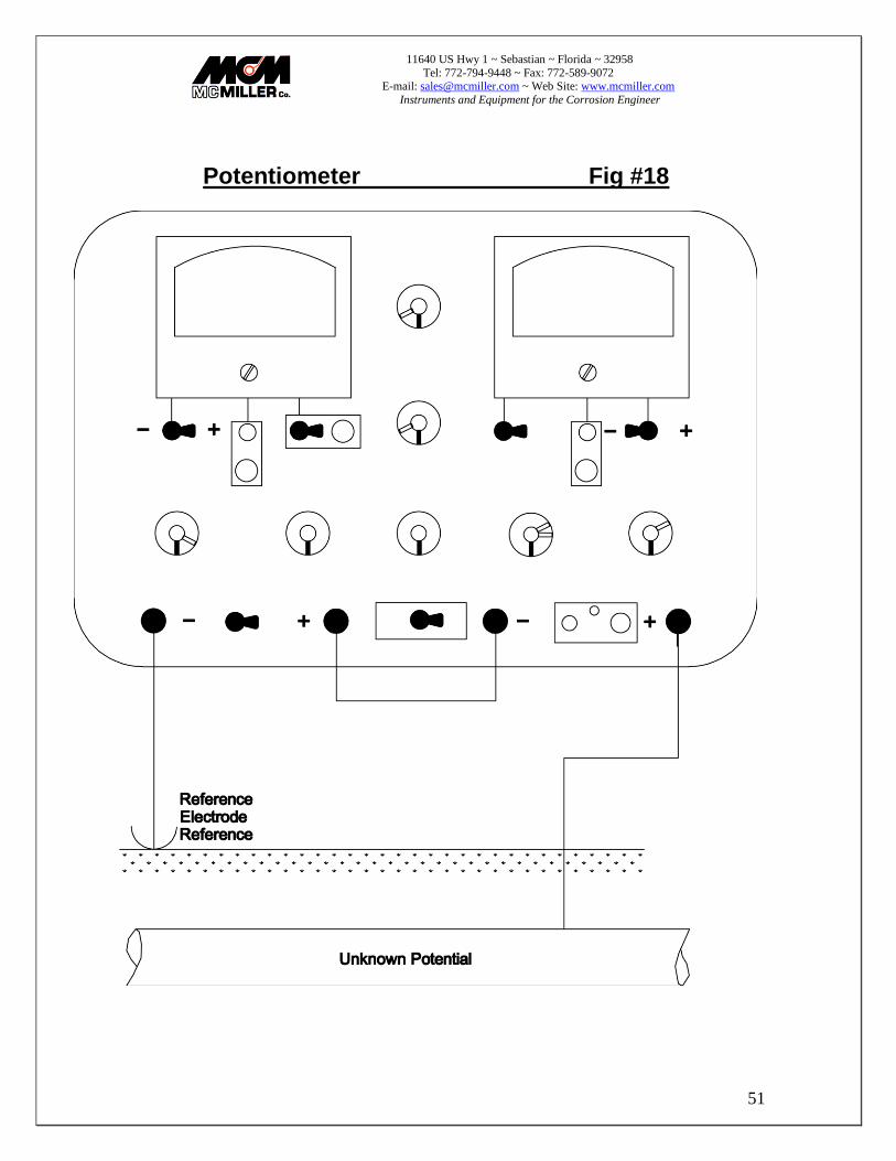
Potentiometer Fig #18

11640 US Hwy 1 ~ Sebastian ~ Florida ~ 32958
Tel: 772-794-9448 ~ Fax: 772-589-9072 E-mail: [email protected] ~ Web Site: www.mcmiller.com
Instruments and Equipment for the Corrosion Engineer
52
26) Potentiometer Fig #18
Because of much higher input resistances available on the Model B3A2 as compared to previous models, a specific Potentiometer / Voltmeter switch position has not been provided. However, the B3A2 can be set up to function as a PM/VM (range 0-3 volts) using the right -hand meter as a highly sensitive galvanometer as follows:
a. Connect positive lead of unknown voltage to negative terminal of the left-hand meter, and negative lead of unknown voltage to positive terminal of right-hand meter.
b. Connect a jumper between the positive terminal of the left –hand
meter and the negative terminal of the right -hand meter.
c. Throw amps toggle switch to "Amps with Controls" position.
d. Turn ammeter range switch to "20A" range.
e. Throw battery toggle switch to "3V" position.
f. Throw right polarity switch to “-“ position.
g. Turn right range switch to the "2V" position.
h. Turn input resistance range switch to the "200M" range.
i. Turn fine and coarse controls clockwise as necessary to bring the pointer on the right-hand meter to zero.
j. Throw "To Left Term Norm" toggle switch to the "To Left Term"
position and read the unknown voltage on the right-hand meter. Note: If the pointer does not deflect toward zero in Step "i", polarity connections in Step "A" were incorrectly made. Reverse input leads. If input is greater than 3 volts, the potentiometer/voltmeter method cannot be used with this meter.

11640 US Hwy 1 ~ Sebastian ~ Florida ~ 32958
Tel: 772-794-9448 ~ Fax: 772-589-9072 E-mail: [email protected] ~ Web Site: www.mcmiller.com
Instruments and Equipment for the Corrosion Engineer
53
Coating Fault Surveys Fig #19

11640 US Hwy 1 ~ Sebastian ~ Florida ~ 32958
Tel: 772-794-9448 ~ Fax: 772-589-9072 E-mail: [email protected] ~ Web Site: www.mcmiller.com
Instruments and Equipment for the Corrosion Engineer
54
27) Coating Fault Surveys Fig #19
Model B3A2 is well suited for making coating fault surveys on buried coated structures such as pipelines, jacketed cables and coated underground storage tanks. The survey consists of electrically isolating the structure under test from all ground connections, and then applying an interrupted negative DC potential to the structure using some other piping system, or ground rod as a temporary reference ground. Voltage readings are then taken between a reference electrode located off to the side of the structure and another reference electrode, which is moved along the surface of the ground at short intervals (for instance, 5 feet) over the structure under test. At locations where there is electrical leakage from areas where the coating has become damaged, there will be produced an easily measured rise in potential. The use of a JR-1 or JR-2 Current Interrupter in the circuit permits the gradient produced by the test current to be seen separately from any other gradient which may exist from some other current source. This is best accomplished by setting the Current Interrupter to a fairly identifiable On-Off cycle (perhaps 2 seconds On and 1 second Off).

11640 US Hwy 1 ~ Sebastian ~ Florida ~ 32958
Tel: 772-794-9448 ~ Fax: 772-589-9072 E-mail: [email protected] ~ Web Site: www.mcmiller.com
Instruments and Equipment for the Corrosion Engineer
55
Resistance-of-Bond-or-Drainage-Resistors Fig #20
11640 US Hwy 1 ~ Sebastian ~ Florida ~ 32958
Tel: 772-794-9448 ~ Fax: 772-589-9072 E-mail: [email protected] ~ Web Site: www.mcmiller.com
Instruments and Equipment for the Corrosion Engineer
56
28) Resistance-of-Bond-or-Drainage-Resistors Fig #20
Using the ammeter circuit and the internal controls, your Model B3A2 can serve as a temporary adjustable bonding connection within the following limits of resistance and current: A. 0.4 ohms to 1.4 ohms at 5 amps continuous or 15 amps for a few seconds B. 0.4 ohms to 22 ohms at 1.3 amps continuous or 2.5 amps for a few seconds C. 0.4 ohms to 500 ohms at .22 amps continuous or 0.5 amps for a few seconds The test procedure consists of connecting a heavy test lead from each of the two pipes or other structures to the left terminals. If the current which flows when the amps toggle switch is thrown to the "Amps" position is less than 10 amperes, the amps toggle switch can then be thrown to the "Amps with Controls" position and the rheostat turned clockwise until the desired current is obtained. This will normally require another meter, and perhaps a JR-1 Current Interrupter to interrupt current from the rectifier in order to determine the point at which drainage or bond current is just sufficient to eliminate the interference effects caused by the rectifier installation. When the controls have been set so as to produce the desired current, the bond resistance can be quickly calculated by dividing the voltage reading on the right-hand meter by the current reading on the left hand meter
11640 US Hwy 1 ~ Sebastian ~ Florida ~ 32958
Tel: 772-794-9448 ~ Fax: 772-589-9072 E-mail: [email protected] ~ Web Site: www.mcmiller.com
Instruments and Equipment for the Corrosion Engineer
57
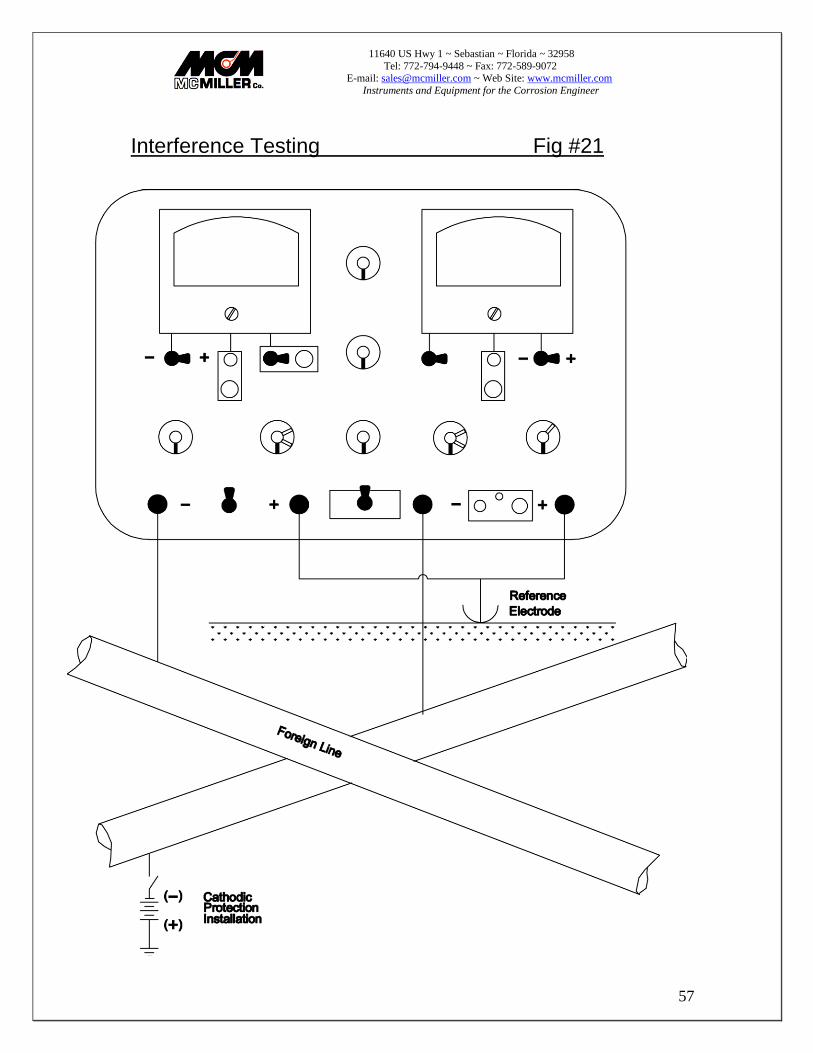
Interference Testing Fig #21
11640 US Hwy 1 ~ Sebastian ~ Florida ~ 32958
Tel: 772-794-9448 ~ Fax: 772-589-9072 E-mail: [email protected] ~ Web Site: www.mcmiller.com
Instruments and Equipment for the Corrosion Engineer
58
29) Interference Testing Fig #21
In areas where two or more underground structures cross or come close together, the cathodic protection installation on one of these structures can have undesirable effects of the structure-to-soil potential of the other structure. This undesirable effect is called interference. The most common method of testing for interference is to employ a Current Interrupter to periodically interrupt the cathodic protection current from one structure while measuring the pipe-to- soil potentials of all foreign structures at close intervals throughout the area of their proximity. The Model B3A2 has two sensitive voltmeters. Each one can be connected so that it measures the pipe-to-soil potential of one of the structures. If the potential on any foreign line swings in a positive direction when the cathodic protection installation is energized, an "interference" condition exists. Action may or may not be required, depending on actual value of the potential obtained. The interference may only be lessening the degree of over-protection rather than causing a corrosion current to flow. Further action must be determined by agreement between the two concerned parties.
11640 US Hwy 1 ~ Sebastian ~ Florida ~ 32958
Tel: 772-794-9448 ~ Fax: 772-589-9072 E-mail: [email protected] ~ Web Site: www.mcmiller.com
Instruments and Equipment for the Corrosion Engineer
59
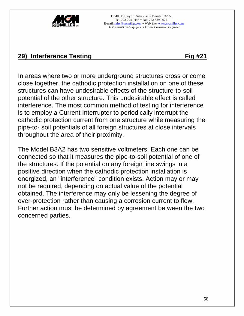
Coating Resistance Tests Fig #22

11640 US Hwy 1 ~ Sebastian ~ Florida ~ 32958
Tel: 772-794-9448 ~ Fax: 772-589-9072 E-mail: [email protected] ~ Web Site: www.mcmiller.com
Instruments and Equipment for the Corrosion Engineer
60
30) Coating Resistance Tests FIG #22
The average resistance of one square foot of pipe coating can be determined by applying a negative potential to the pipe using a cathodic protection rectifier installation or storage batteries and a temporary ground bed located at least 100' away from the pipe. The average change in potential produced by the test current is then determined on the basis of at least two measurements. ACR = _ACP_ x Area of Pipe Coating TCP
ACR = Average Coating Resistance; ACP = Average Change in Potential; TCP = Test Current Picked Up In Section Under test Because resistance values tend to be high, some people prefer to use conductance rather than resistance. The unit of conductance is the siemens (formerly Mho). Coating conductivity is often given in terms of micro-siemens. Conductance = 1______ Resistance
)
)
(
(
11640 US Hwy 1 ~ Sebastian ~ Florida ~ 32958
Tel: 772-794-9448 ~ Fax: 772-589-9072 E-mail: [email protected] ~ Web Site: www.mcmiller.com
Instruments and Equipment for the Corrosion Engineer
61
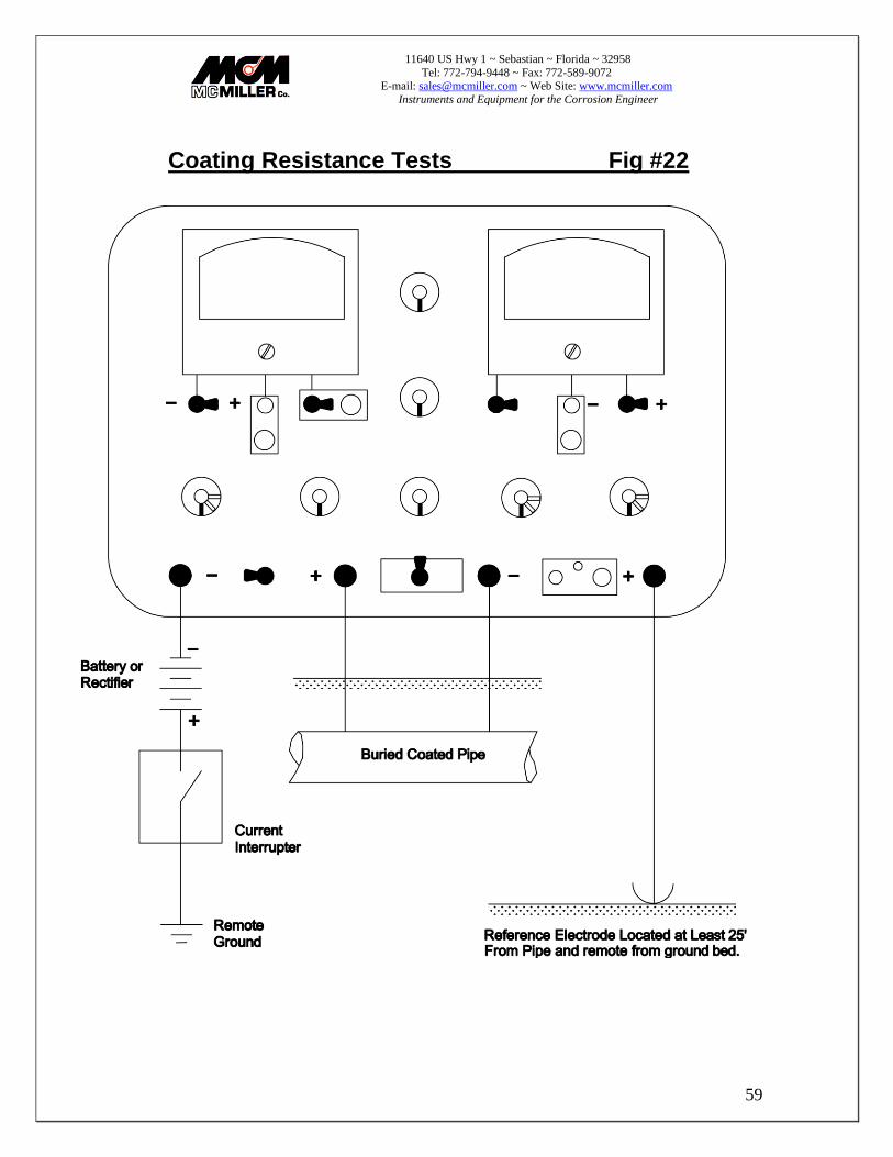
Calibrating IR Drop Test Station Fig #23

11640 US Hwy 1 ~ Sebastian ~ Florida ~ 32958
Tel: 772-794-9448 ~ Fax: 772-589-9072 E-mail: [email protected] ~ Web Site: www.mcmiller.com
Instruments and Equipment for the Corrosion Engineer
62
31) Calibrating IR Drop Test Station Fig #23
For several types of corrosion tests it is vital to know how much direct current is flowing at various points along a pipe or cable and to know the direction of current flow. At present the only practical method on most pipes or cables, particularly the larger ones, is to use a section of the pipe or cable as a current measuring shunt. This is accomplished by making four connections to the structure and bringing these wires up to a test station. The resistance of the shunt can be calculated if both the length of the test span and the resistance per foot of the structure are known accurately. However, the resistance varies with temperature and contractors do not always measure the span accurately. For these reasons many companies prefer to calibrate the test station using measured current from a storage battery to produce an IR drop in the structure which can be accurately measured using a millivoltmeter. Since there will often be an existing current in the structure, it is essential that the millivolt drop be measured with the test current off and then again with the test current applied. The algebraic difference between the two readings is then used to make the calculation. For example, if the existing mV IR drop in the test span is 0.21mV with the east end being positive, and the IR drop with 10 amperes test current applied is 3.39mV with the east end being negative, the algebraic difference produced by the test current = 3.39 + .21 = 3.60mV. The calibration of this test station would be 0.36mV per ampere, which also can be expressed as 2.78 amperes per mV. For a pipe of 24" or larger, the test current should be at least 10 amperes. It is not necessary to know the span or the diameter of the pipe or cable in order to calibrate the test station. Once the span has been calibrated it is not necessary to repeat the calibration procedure unless the temperature of the structure has changed considerably. Radical changes of pipe temperature often occur downstream
11640 US Hwy 1 ~ Sebastian ~ Florida ~ 32958
Tel: 772-794-9448 ~ Fax: 772-589-9072 E-mail: [email protected] ~ Web Site: www.mcmiller.com
Instruments and Equipment for the Corrosion Engineer
63
from gas compressor stations. Power cable and pipe type cable installations can also change temperature considerably. The relative location of the test leads must be known if the direction of current flow is to be determined. If the relative location of the test leads is not known, it can be determined by turning on and off a nearby cathodic protection rectifier. When the rectifier is on, the current flow should be towards the rectifier. 32) Maintenance of Panel & Case
Both the meter panel and the "Pelican" case are surfaced with a layer of melamine resin which is unusually resistant to wear and tear resulting from normal use. For appearance sake and to prevent possible surface leakage of electrical currents, we recommend that the panel be kept reasonably free of dirt. Clean with a small folded cloth dampened with denatured alcohol or soap and water. The panel should be allowed to dry thoroughly before use. Clean the case in a similar manner. 33) Effects of Static Electricity
In dry climates or under winter conditions rubbing or dusting off the meter glass may produce a static charge on the glass that attracts or repels the instrument pointer, thus producing an apparent error or causing the meter to appear defective. The quickest way to dissipate the charge is to wipe the glass with a clean cloth slightly moistened with water or to breathe heavily on the glass until it becomes temporarily clouded with condensation. The use of anti-static compounds on the glass will also be helpful. Re-application will usually be necessary every few days. 34) Transportation of Meter
The Model B3A2 is designed to be transported in any position. Preferred transport methods in a vehicle would be on the seat with seat belt fastened through the handle or in a foam padded bin. If the meter is to be shipped it should be in a sturdy container with at least 1-1/2" of plastic foam padding or foam plastic pellets surrounding the meter on all sides.
11640 US Hwy 1 ~ Sebastian ~ Florida ~ 32958
Tel: 772-794-9448 ~ Fax: 772-589-9072 E-mail: [email protected] ~ Web Site: www.mcmiller.com
Instruments and Equipment for the Corrosion Engineer
64
35) Calibration of Model B3A2
Test Equipment Required:
a. DC power supply or calibrator with voltage ranges from 2mV to 100V with accuracy of .1% or better, and output impedance of 2 ohms maximum.
b. DC current supply with ranges of from 2mA to 20A at an accuracy of .1% or better.
c. DC voltmeter with a range of 0 to 20V at an accuracy of 1% or better. d. DC power supply capable of producing 10V @ 2mA.
Calibration Procedure (Left-Hand Meter):
a. With voltage range switch in the "Off' position, adjust mechanical zero adjust in the center of meter cover as necessary.
b. Remove left amplifier 9V battery and substitute DC power supply. Adjust
power supply for an output of 6.8V +/- .01VDC. Turn range switch to “BAT” position and adjust 500 ohm trim pot located on rear of printed circuit board (next to “BAT connector) until pointer rests on low mark of “Bat’y Test” range. Approximately .79 on lower meter scale). Increase power supply and replace battery after testing for greater than 6.8V.
c. Turn voltage range switch to the "2mV" position and adjust the electronic
zero adjust using push-button and control on front of panel. Readjust as necessary during calibration procedure. It is suggested that the meter be left on the “2mV” range for at least 5 minutes to allow for normal warm-up zero drift.
d. A 1000 ohm trim pot located near the front of the printed circuit board,
between the input resistance and Volts range switches, is used to calibrate all voltage and current ranges to full scale. With the Amps toggle switch in the “Volts” position, apply 2mV to left meter terminals and adjust pot for full scale deflection +/- .5%. As a check, apply full scale voltage to each successive range. A "happy medium" adjustment is advised so that all ranges fall between 99.5% and 100.5% of full scale. Any range which exceeds this tolerance must be corrected by the replacement of the appropriate range resistor.
11640 US Hwy 1 ~ Sebastian ~ Florida ~ 32958
Tel: 772-794-9448 ~ Fax: 772-589-9072 E-mail: [email protected] ~ Web Site: www.mcmiller.com
Instruments and Equipment for the Corrosion Engineer
65
e. To check current ranges, place voltage range switch in the “Off” position; throw amps toggle switch to “Amps” position; and check all current ranges using the DC current supply. There us no calibration adjustment for the current ranges.
Calibration Procedure (Right-Hand Meter):
a. With voltage range switch in the "Off' position, adjust mechanical zero
adjust in the center of meter cover as necessary.
b. Remove right amplifier 9V battery and substitute DC power supply. Adjust power supply for an output of 6.8VDC +/- .01 VDC. Place right hand polarity switch in " + " position and turn range switch to "BAT" position. Locate 500 ohm trim pot located on rear of right amplifier printed circuit board near "MTR" connector. Adjust pot until pointer rests on low mark of "Bat'y Test" range, approximately .79 on lower meter scale. Increase power supply voltage to 10VDC. Pointer should read around full scale. Remove power supply and replace battery after testing for greater than 6.8V.
c. Turn voltage range switch to the "2mV" position and adjust the electronic zero after a 5 minute warm-up period. Re-adjust as necessary throughout the calibration procedure.
d. A 1000 ohm trim pot located near the front of the printed circuit board,
between the input resistance and Volts range switches, is used to calibrate all voltage ranges to full scale. Apply 2mV to left meter terminals and adjust pot for full scale deflection + /- .5%. As a check, apply full scale voltage to each successive range. A "happy medium" adjustment is advised so that all ranges fall between 99.5% and 100.5% of full scale. Any range which exceeds this tolerance must be corrected by the replacement of the appropriate range resistor.
11640 US Hwy 1 ~ Sebastian ~ Florida ~ 32958
Tel: 772-794-9448 ~ Fax: 772-589-9072 E-mail: [email protected] ~ Web Site: www.mcmiller.com
Instruments and Equipment for the Corrosion Engineer
66
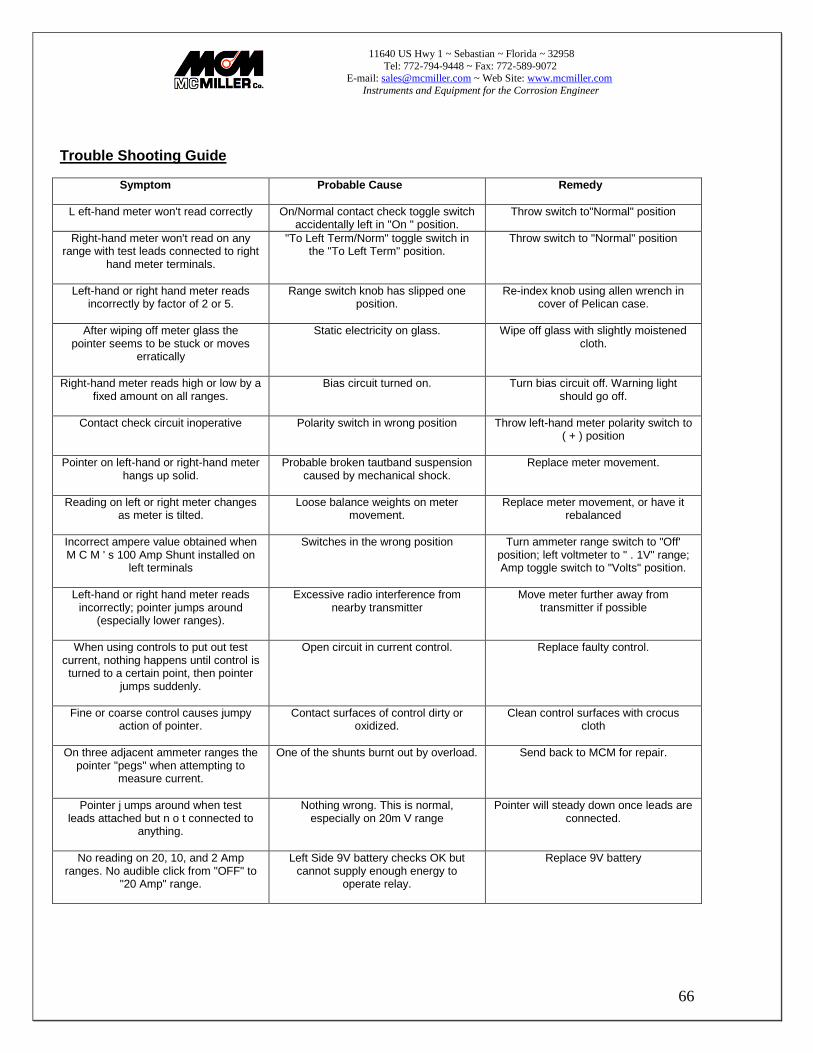
Trouble Shooting Guide Symptom
Probable Cause Remedy
L eft-hand meter won't read correctly On/Normal contact check toggle switch accidentally left in "On " position.
Throw switch to"Normal" position
Right-hand meter won't read on any range with test leads connected to right
hand meter terminals.
"To Left Term/Norm" toggle switch in the "To Left Term" position.
Throw switch to "Normal" position
Left-hand or right hand meter reads incorrectly by factor of 2 or 5.
Range switch knob has slipped one position.
Re-index knob using allen wrench in cover of Pelican case.
After wiping off meter glass the pointer seems to be stuck or moves
erratically
Static electricity on glass. Wipe off glass with slightly moistened cloth.
Right-hand meter reads high or low by a fixed amount on all ranges.
Bias circuit turned on. Turn bias circuit off. Warning light should go off.
Contact check circuit inoperative
Polarity switch in wrong position Throw left-hand meter polarity switch to ( + ) position
Pointer on left-hand or right-hand meter hangs up solid.
Probable broken tautband suspension caused by mechanical shock.
Replace meter movement.
Reading on left or right meter changes as meter is tilted.
Loose balance weights on meter movement.
Replace meter movement, or have it rebalanced
Incorrect ampere value obtained when M C M ' s 100 Amp Shunt installed on
left terminals
Switches in the wrong position Turn ammeter range switch to "Off' position; left voltmeter to " . 1V" range; Amp toggle switch to "Volts" position.
Left-hand or right hand meter reads incorrectly; pointer jumps around
(especially lower ranges).
Excessive radio interference from nearby transmitter
Move meter further away from transmitter if possible
When using controls to put out test current, nothing happens until control is turned to a certain point, then pointer
jumps suddenly.
Open circuit in current control. Replace faulty control.
Fine or coarse control causes jumpy action of pointer.
Contact surfaces of control dirty or oxidized.
Clean control surfaces with crocus cloth
On three adjacent ammeter ranges the pointer "pegs" when attempting to
measure current.
One of the shunts burnt out by overload. Send back to MCM for repair.
Pointer j umps around when test leads attached but n o t connected to
anything.
Nothing wrong. This is normal, especially on 20m V range
Pointer will steady down once leads are connected.
No reading on 20, 10, and 2 Amp ranges. No audible click from "OFF" to
"20 Amp" range.
Left Side 9V battery checks OK but cannot supply enough energy to
operate relay.
Replace 9V battery

11640 US Hwy 1 ~ Sebastian ~ Florida ~ 32958
Tel: 772-794-9448 ~ Fax: 772-589-9072 E-mail: [email protected] ~ Web Site: www.mcmiller.com
Instruments and Equipment for the Corrosion Engineer
67
37) B3A2 Level One Parts List
DESCRIPTION ORDER #
MULTIMEIER MODEL B3A2 908 BTRY, #950, 1.5v, D BATOO1 BTRY, #E91AA, 1.5v, AA, AL BATOO3 BTRY, #1222, 9V BAT007 BTRY RETAIN CLIP, A, #61 BAT016 BTRY RETAIN CLIP, C, #62 BAT017 BTRY RETAIN CLIP, D, #63 BAT018 CASE, FORMICA, B3Al & 2 CASOO1 3-CONDUCTOR CONNECTER CON028 5-CONDUCTOR CONNECTER CON034 STANDOFF, HEX, 1-7/16, BN CON055 KNOB, BAR, #RB671BSKMX KNOOO1 KNOB, BAR, 1/8" RB671BSK KNOOO4 KNOB, RND, #RB670DCMX KNOOO6 CUBELITE LENS, REDIBIAS MIS007 LED LIGHT, #HLMPD150 MISOO8 METER, 420, 1MA/12.5, 10% MfROO3 GASKET, 420 METER MTROO8 PANEL MULTIMETER, B3A2 PANOO110 POT, CER, PANEL, 50 OHM POTlOO10 POT, C/P, 20K (MOD) POT510 REO, OHMITE, 1, TYPE H POT600 REO, OHMITE,15, TYPE H POT6001 REO, OHMITE, 500, TYPE H POT602 RES, WW, .1, .6W, .25% RES610 R/H B3A2 AMPL ASSY SUB035 L/H B3A2 AMPL ASSY SUB036 ( + ) R/H FEED-TRU ASSY SUB075 ( + ) L/H FEED-TRU ASSY SUB076 ( - ) R/H FEED-TRU ASSY SUB077 ( - ) L/H FEED-TRU ASSY SUB078 SHUNT ASSY, B/M A2 SUB082 BTRY PLATFORM, B3A2 SUBl0010 RELAY W/SNUB CIRCUIT 12902 TOGGLE SW, "AMP" SWI300 TOGGLE SW, 7301, 3P, D/T SWI301 TOGGLE SW, 7201, 2P, D/T SWI302 TOG SW, 7203, 2P, D/T. C/O SWI303 SWITCH BOOT, #5168 SWI350 P/B SWITCH, #913 SWI400 TERM, RED, SMITH #459 TERO11 TERM, BLK, SMITH #459 TER012
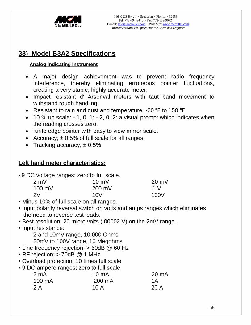
11640 US Hwy 1 ~ Sebastian ~ Florida ~ 32958
Tel: 772-794-9448 ~ Fax: 772-589-9072 E-mail: [email protected] ~ Web Site: www.mcmiller.com
Instruments and Equipment for the Corrosion Engineer
68
38) Model B3A2 Specifications
Analog indicating Instrument
A major design achievement was to prevent radio frequency interference, thereby eliminating erroneous pointer fluctuations, creating a very stable, highly accurate meter.
Impact resistant d' Arsonval meters with taut band movement to withstand rough handling.
Resistant to rain and dust and temperature: -20 °F to 150 °F 10 % up scale: -.1, 0, 1: -.2, 0, 2: a visual prompt which indicates when
the reading crosses zero.
Knife edge pointer with easy to view mirror scale.
Accuracy; ± 0.5% of full scale for all ranges.
Tracking accuracy; ± 0.5%
Left hand meter characteristics:
• 9 DC voltage ranges: zero to full scale. 2 mV 10 mV 20 mV 100 mV 200 mV 1 V 2V 10V 100V
• Minus 10% of full scale on all ranges. • Input polarity reversal switch on volts and amps ranges which eliminates the need to reverse test leads. • Best resolution; 20 micro volts (.00002 V) on the 2mV range. • Input resistance:
2 and 10mV range, 10,000 Ohms 20mV to 100V range, 10 Megohms
• Line frequency rejection; > 60dB @ 60 Hz • RF rejection; > 70dB @ 1 MHz • Overload protection: 10 times full scale • 9 DC ampere ranges; zero to full scale
2 mA 10 mA 20 mA 100 mA 200 mA 1A 2 A 10 A 20 A
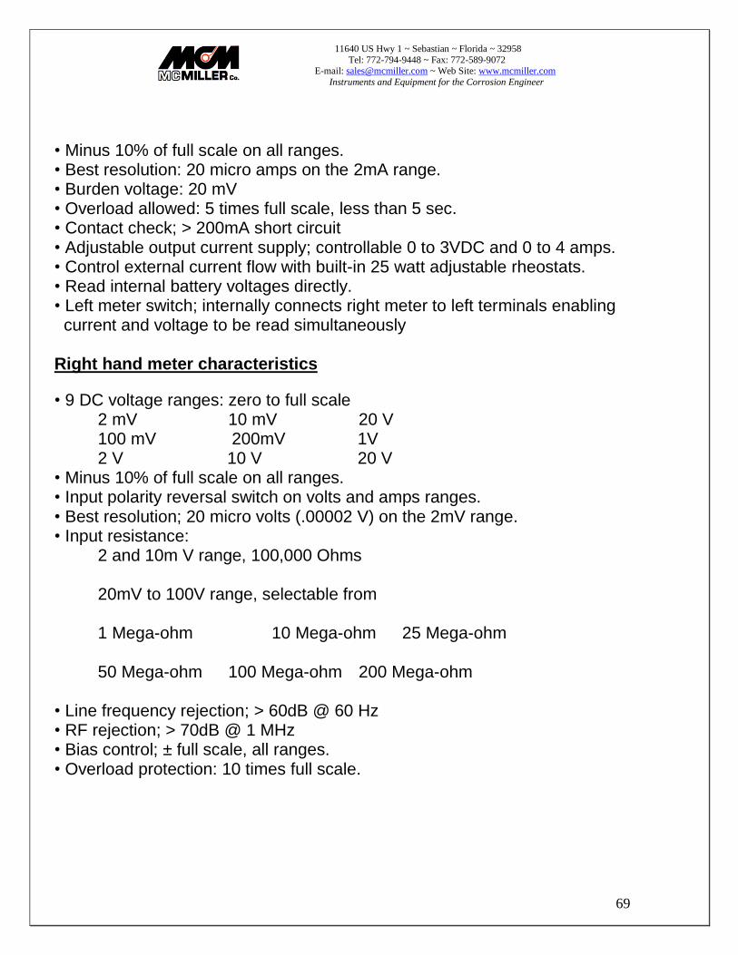
11640 US Hwy 1 ~ Sebastian ~ Florida ~ 32958
Tel: 772-794-9448 ~ Fax: 772-589-9072 E-mail: [email protected] ~ Web Site: www.mcmiller.com
Instruments and Equipment for the Corrosion Engineer
69
• Minus 10% of full scale on all ranges. • Best resolution: 20 micro amps on the 2mA range. • Burden voltage: 20 mV • Overload allowed: 5 times full scale, less than 5 sec. • Contact check; > 200mA short circuit • Adjustable output current supply; controllable 0 to 3VDC and 0 to 4 amps. • Control external current flow with built-in 25 watt adjustable rheostats. • Read internal battery voltages directly. • Left meter switch; internally connects right meter to left terminals enabling current and voltage to be read simultaneously Right hand meter characteristics
• 9 DC voltage ranges: zero to full scale 2 mV 10 mV 20 V 100 mV 200mV 1V 2 V 10 V 20 V
• Minus 10% of full scale on all ranges. • Input polarity reversal switch on volts and amps ranges. • Best resolution; 20 micro volts (.00002 V) on the 2mV range. • Input resistance:
2 and 10m V range, 100,000 Ohms 20mV to 100V range, selectable from 1 Mega-ohm 10 Mega-ohm 25 Mega-ohm 50 Mega-ohm 100 Mega-ohm 200 Mega-ohm
• Line frequency rejection; > 60dB @ 60 Hz • RF rejection; > 70dB @ 1 MHz • Bias control; ± full scale, all ranges. • Overload protection: 10 times full scale.