smart ground multi meter - atis ground... · smart ground multi‐meter ... • the soil...
TRANSCRIPT
Smart Ground Multi‐Meter
Joe BoylesBoyles Electronics
SGM
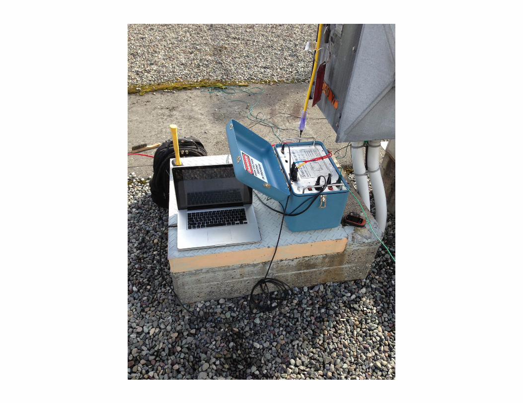
• The Smart Ground® Multimeter, or SGM, is a computer controlled multi‐function instrument for measuring grounding systems.
• Developed by Dr Sakis Meliopolis with the sponsorship of EPRI.

SGM
SGM
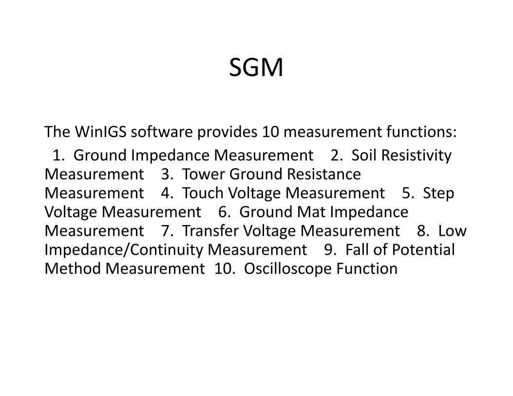
The WinIGS software provides 10 measurement functions:1. Ground Impedance Measurement 2. Soil Resistivity Measurement 3. Tower Ground Resistance Measurement 4. Touch Voltage Measurement 5. Step Voltage Measurement 6. Ground Mat Impedance Measurement 7. Transfer Voltage Measurement 8. Low Impedance/Continuity Measurement 9. Fall of Potential Method Measurement10. Oscilloscope Function

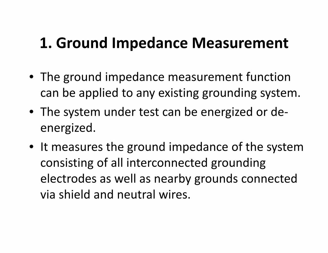
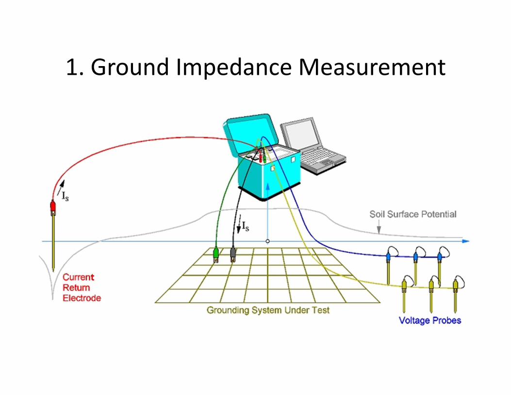
1. Ground Impedance Measurement
• The ground impedance measurement function can be applied to any existing grounding system.
• The system under test can be energized or de‐energized.
• It measures the ground impedance of the system consisting of all interconnected grounding electrodes as well as nearby grounds connected via shield and neutral wires.
1. Ground Impedance Measurement
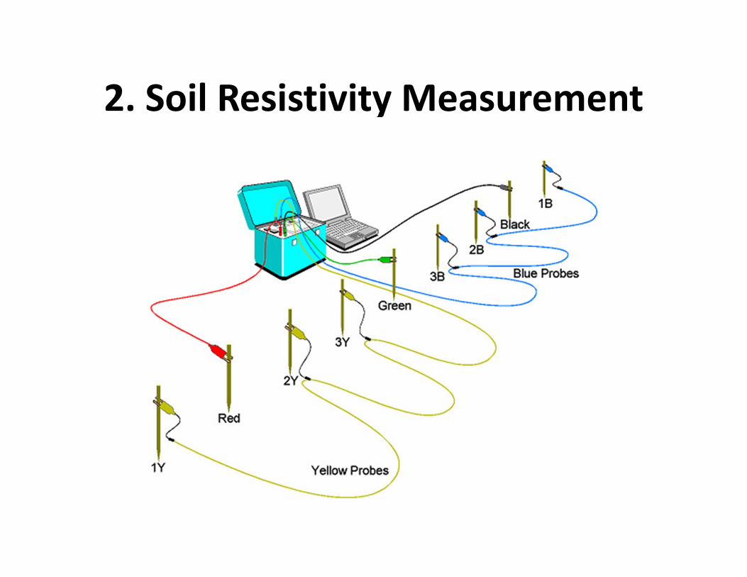
2. Soil Resistivity Measurement
• The soil resistivity function is based on an extension of the four‐pin Wenner method.
• The SGM takes simultaneous measurements on nine probes uniformly spaced along a line on the soil surface.
• Provides an equivalent 2‐Layer resistivity model.
2. Soil Resistivity Measurement
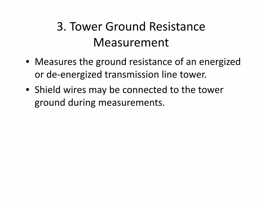
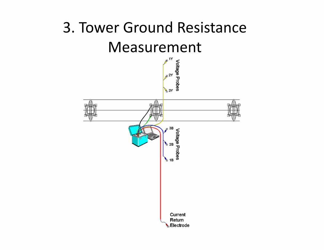
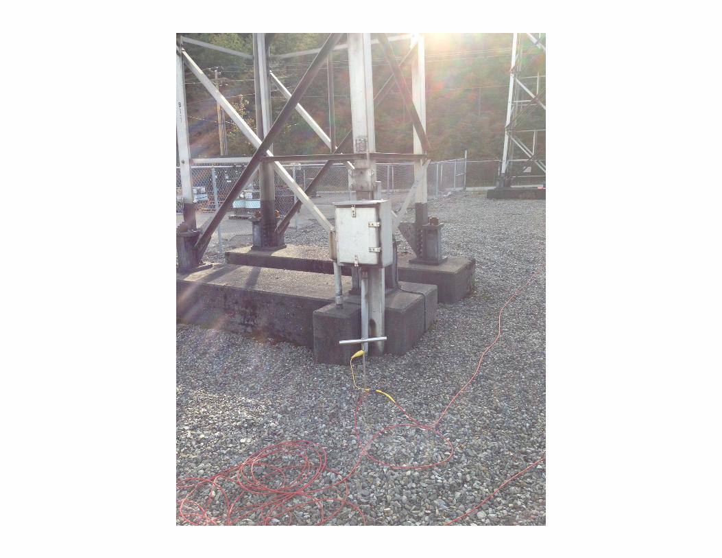
3. Tower Ground Resistance Measurement
• Measures the ground resistance of an energized or de‐energized transmission line tower.
• Shield wires may be connected to the tower ground during measurements.
3. Tower Ground Resistance Measurement
4. Touch Voltage Measurement
• Measures the actual touch voltage at a substation as a function of the fault current.
• The measurement is performed at up to six points near a grounding system.

4. Touch Voltage Measurement

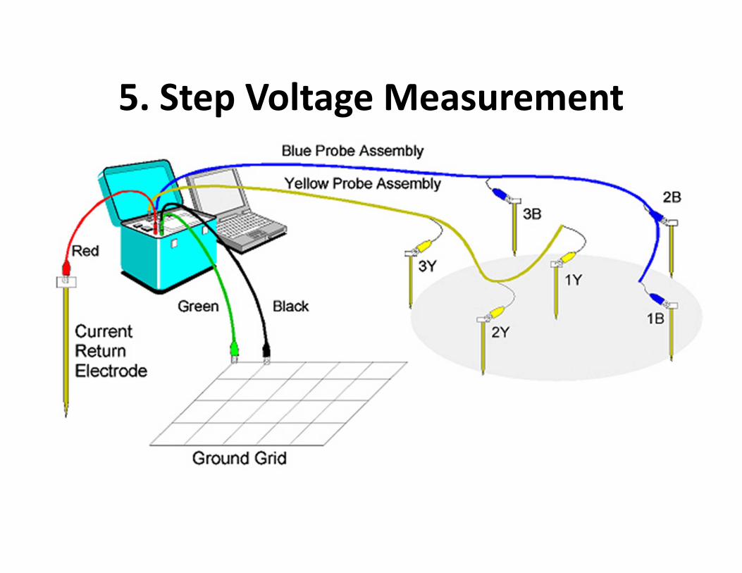
5. Step Voltage Measurement
• Measures the actual step voltage at a substation as a function of the fault current.
• The measurement is performed at a user‐selected point near a grounding system.
5. Step Voltage Measurement
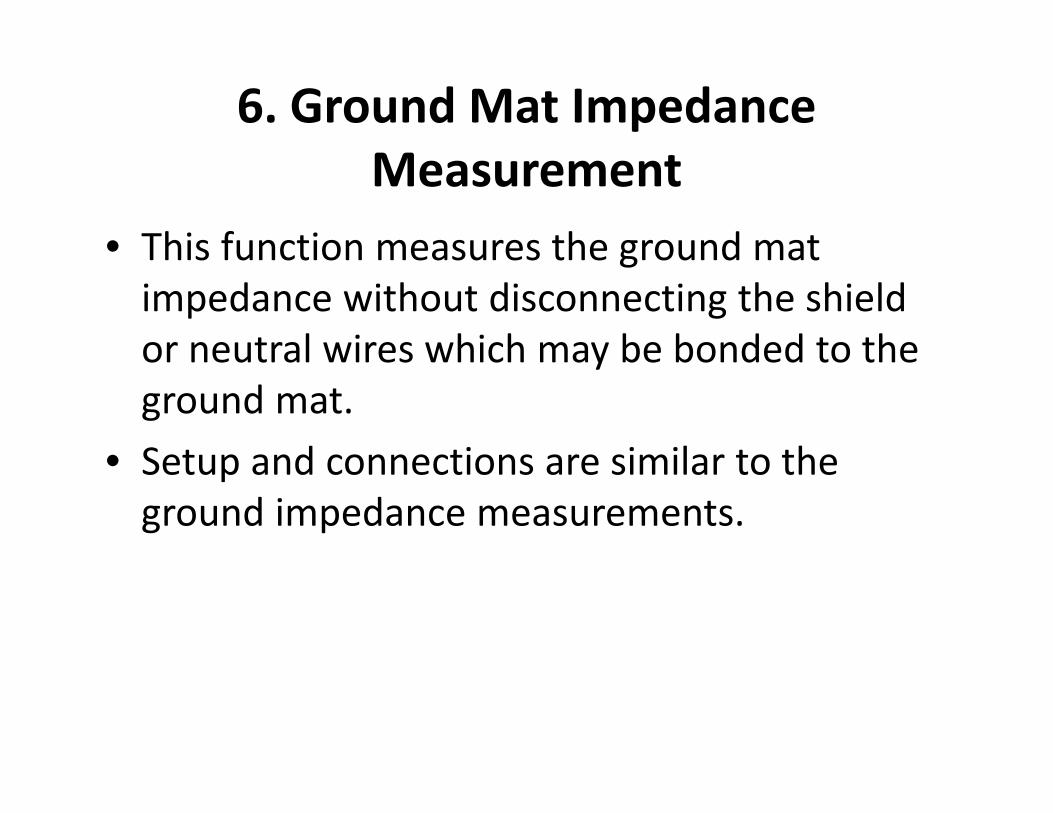
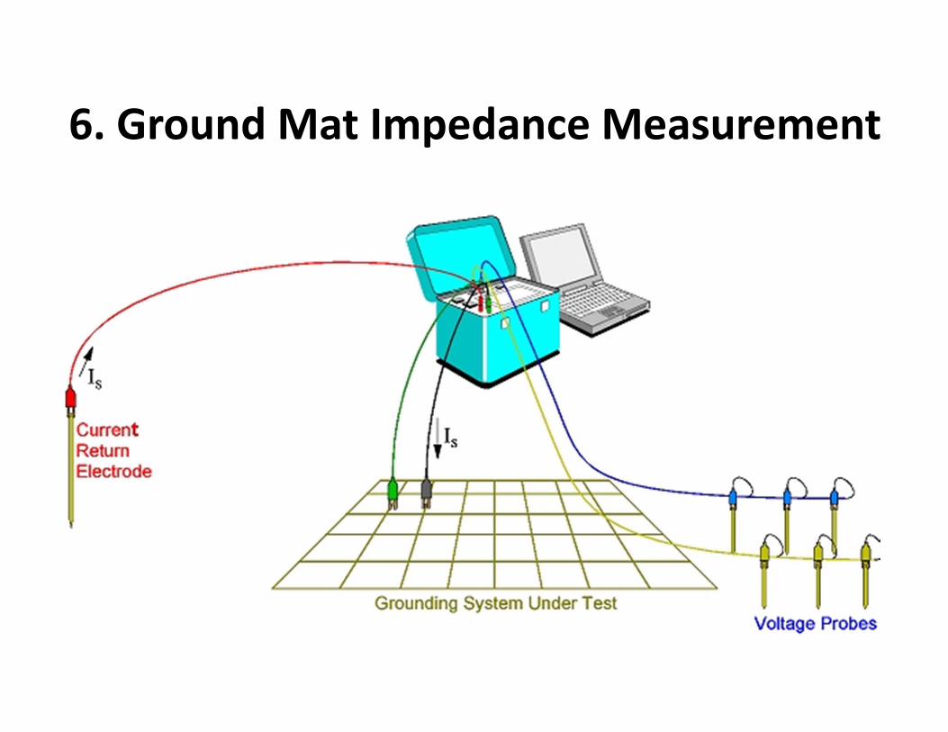
6. Ground Mat Impedance Measurement
• This function measures the ground mat impedance without disconnecting the shield or neutral wires which may be bonded to the ground mat.
• Setup and connections are similar to the ground impedance measurements.
6. Ground Mat Impedance Measurement
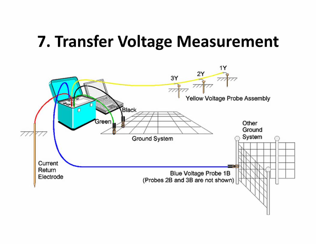
7. Transfer Voltage Measurement
• Measures the transfer voltage at a user‐selected point or ground. This could be a probe at a specific location such as a proposed CFJ site.
• Measures the voltage as a function of the fault current.
7. Transfer Voltage Measurement
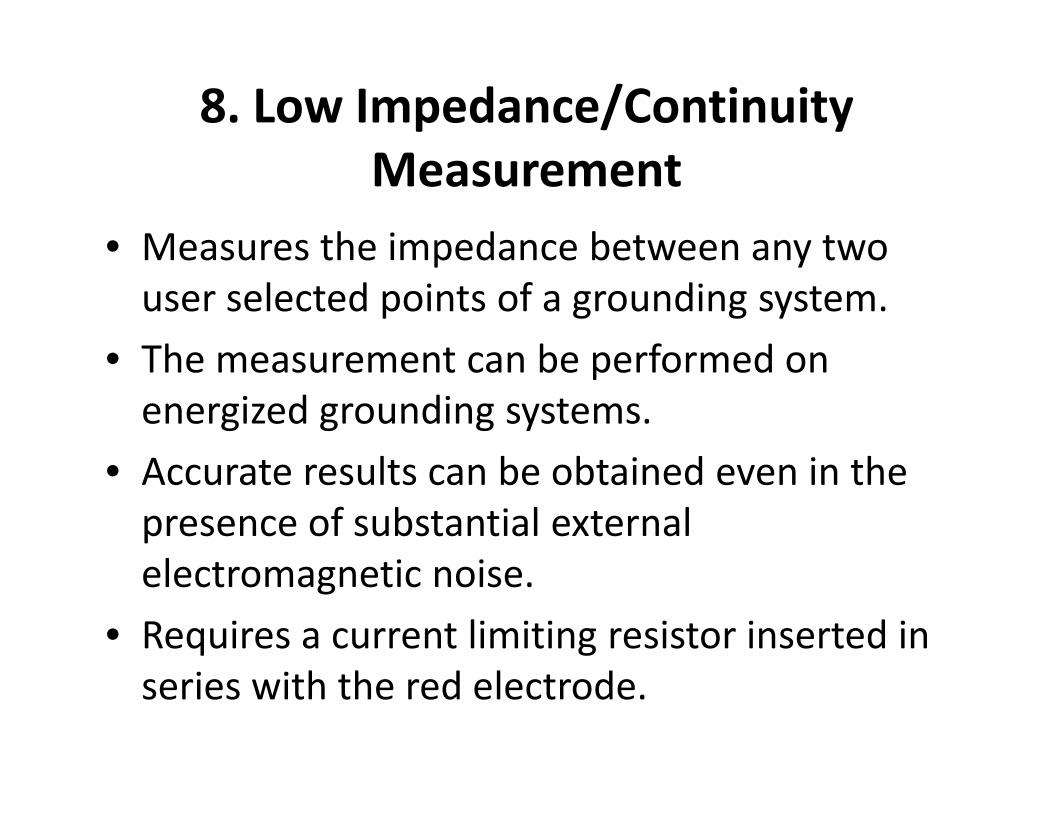
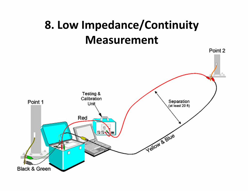
8. Low Impedance/Continuity Measurement
• Measures the impedance between any two user selected points of a grounding system.
• The measurement can be performed on energized grounding systems.
• Accurate results can be obtained even in the presence of substantial external electromagnetic noise.
• Requires a current limiting resistor inserted in series with the red electrode.
8. Low Impedance/Continuity Measurement
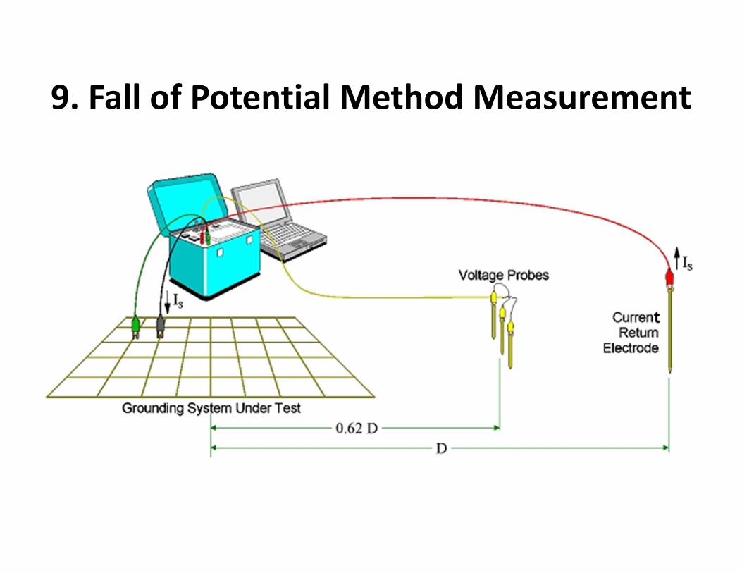
9. Fall of Potential Method Measurement
• Allows using the SGM to perform a ground impedance measurement using the fall‐of‐potential method.
• The required setup for this function is the standard fall‐of‐potential probe arrangement.
9. Fall of Potential Method Measurement

10. Oscilloscope Function
• Allows the SGM to be used as a general purpose six channel waveform data acquisition system.
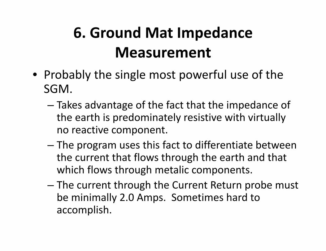
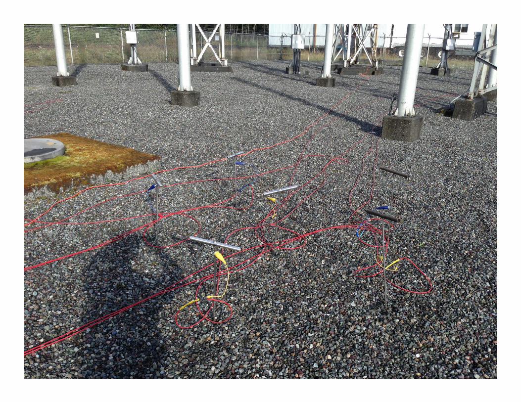
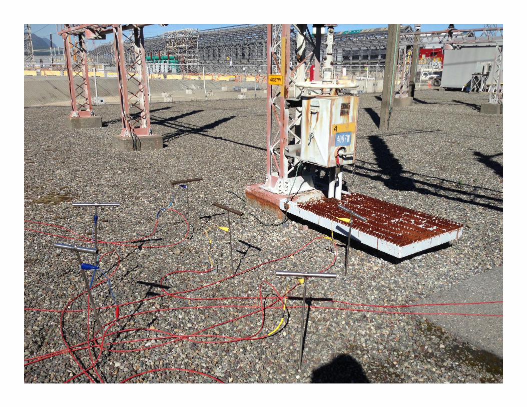
6. Ground Mat Impedance Measurement
• Probably the single most powerful use of the SGM.– Takes advantage of the fact that the impedance of the earth is predominately resistive with virtually no reactive component.
– The program uses this fact to differentiate between the current that flows through the earth and that which flows through metalic components.
– The current through the Current Return probe must be minimally 2.0 Amps. Sometimes hard to accomplish.

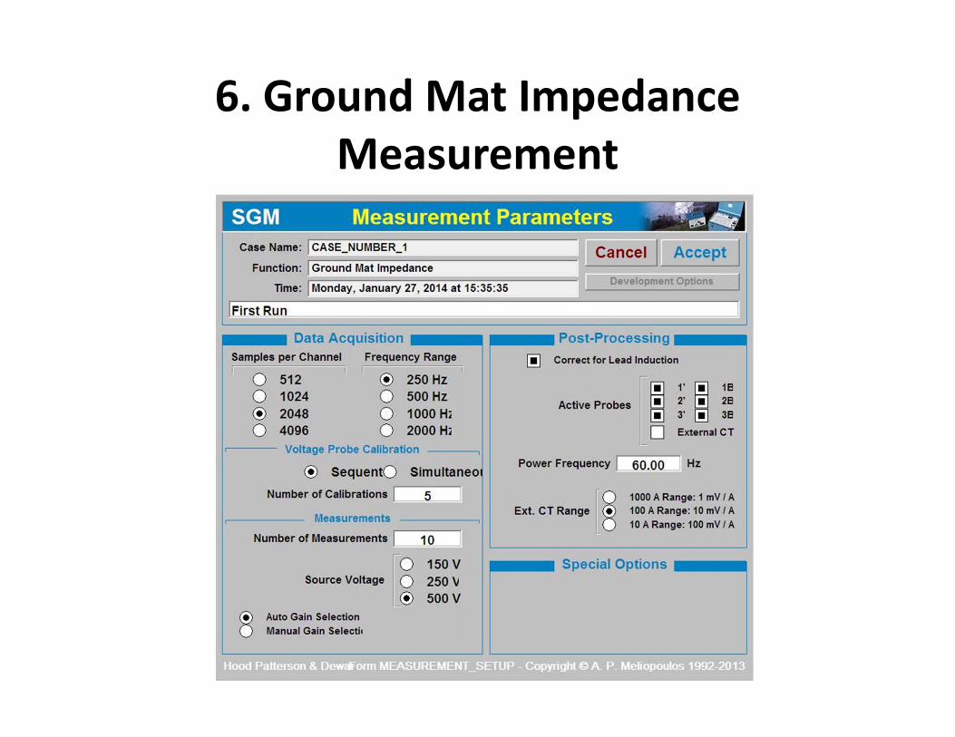
6. Ground Mat Impedance Measurement

Case:
Proceed
CASE_NUMBER_1
Soil Resistivity
1Y2Y3Y
1B2B3B
184.31173.26129.20
157.67476.05384.51
Remove
Remove
Remove
Remove
Remove
Remove
Probe
Cancel
91.485.964.0
78.1236.0190.6
3.003.434.33
0.200.000.00
Resistance
Inductance
(mH)Error
(%)
2.272.536.42
1.381.353.70
205.79Average*
102.0
Capacitance
0.000.000.00
0.000.030.01
(pF)
Average*
- m)
Maximum valueis omitted
* NOTE
SGM Probe Performance Report
Hood Patterson & Dewar Form PROBE_PERF - Copyright © A. P. Meliopoulos 1992-2013

Case Name:
Proceed
CASE_NUMBER_18.00 Amperes RMSInjected Current:
%Valid %Error Quality1Y2Y3Y1B2B3B
80.7776.9275.6480.7778.2175.64
Remov
Remov
Remov
Remov
Remov
Remov
Prb #
Cancel
2.452.572.702.102.222.45
184.3173.3129.2157.7476.0384.5
Very GoodVery GoodVery GoodVery GoodVery GoodVery Good
Resistance(Ohms)
SGM Data Acquisition Performance
0.99710.99540.99340.99730.99610.9938
Average-SquaredCoherence
Hood Patterson & Dewar Form DAQ_PERF - Copyright © A. P. Meliopoulos 1992-2013
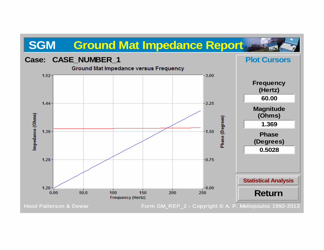
60.00
1.369
0.5028(Degrees)
(Ohms)
Frequency
Plot Cursors
Phase
Magnitude
(Hertz)
Case: CASE_NUMBER_1
ReturnStatistical Analysis
SGM Ground Mat Impedance Report
Hood Patterson & Dewar Form GM_REP_2 - Copyright © A. P. Meliopoulos 1992-2013

Case:
Conf.% Error %
ReturnCASE_NUMBER_1
0.00 4.0%0.00 8.0%7.25 12.0%99.99 16.0%100.00 20.0%
Probe Performance Index0.12 1Y
2Y3Y
1B2B3B
0.11 0.05
0.09 0.07 0.03
Error Vs Confidence Level
SGM Statistical Analysis
Hood Patterson & Dewar Form ERR_CONF - Copyright © A. P. Meliopoulos 1992-2013
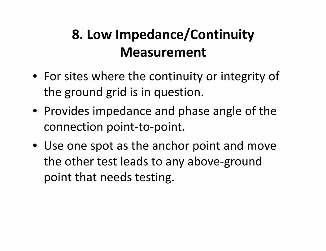
• For sites where the continuity or integrity of the ground grid is in question.
• Provides impedance and phase angle of the connection point‐to‐point.
• Use one spot as the anchor point and move the other test leads to any above‐ground point that needs testing.
8. Low Impedance/Continuity Measurement
Case Name CONLEY_TAP_PTP
60.00
0.05347
75.39
Frequency
Impedance
PhaseDegrees
Ohms
Hz
Cursor ValuesDescription Measure between yards.
11/12/2013 08:08Time
0.01349
0.05174
Resistance
ReactanceOhms
Ohms
0.1372Inductance
mH
Close SGM Impedance Report
Hood Patterson & Dewar Form ZT_REP_1 - Copyright © A. P. Meliopoulos 1992-2013
Case_1
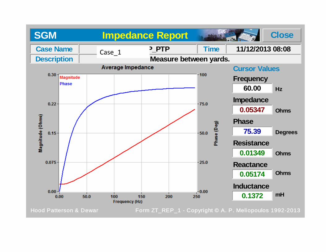
Case Name CONLEY_TAP_PTP
60.00
0.02217
87.41
Frequency
Impedance
PhaseDegrees
Ohms
Hz
Cursor ValuesDescription From Common point 4 to 9
11/12/2013 08:42Time
0.001002
0.02215
Resistance
ReactanceOhms
Ohms
0.05874Inductance
mH
Close SGM Impedance Report
Hood Patterson & Dewar Form ZT_REP_1 - Copyright © A. P. Meliopoulos 1992-2013
Case 1
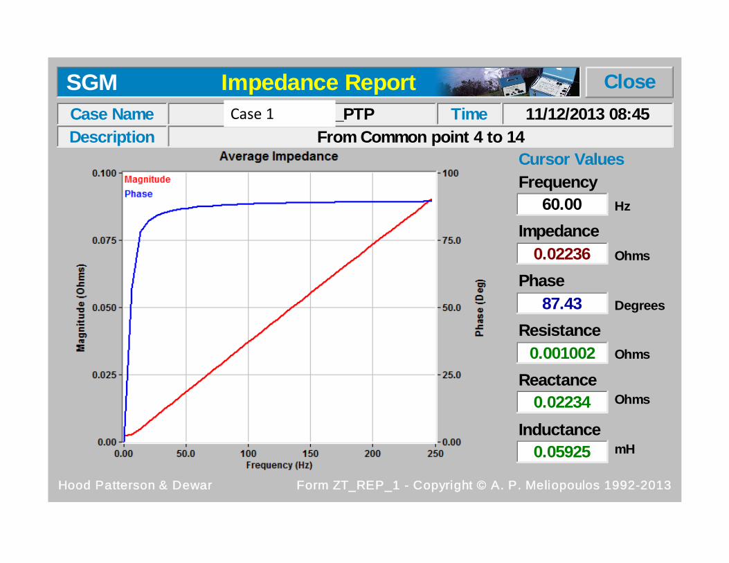
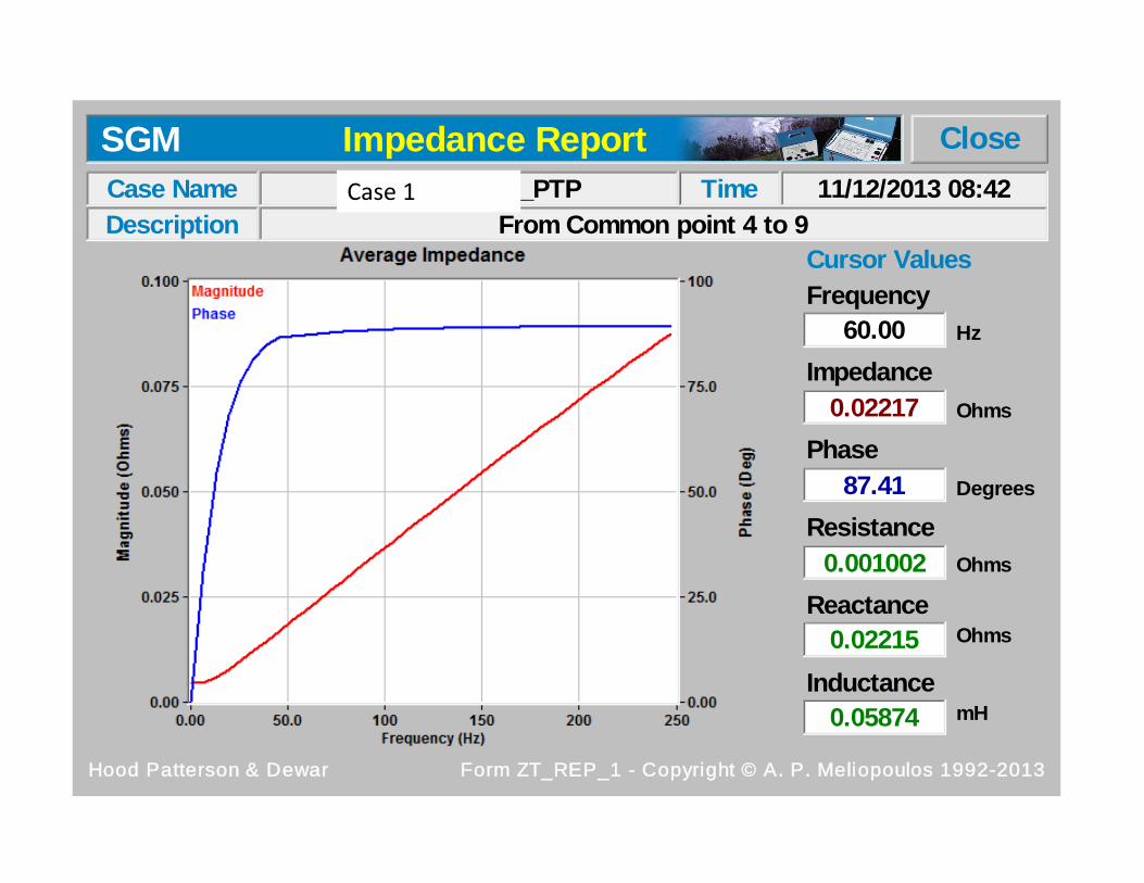
Case Name CONLEY_TAP_PTP
60.00
0.02236
87.43
Frequency
Impedance
PhaseDegrees
Ohms
Hz
Cursor ValuesDescription From Common point 4 to 14
11/12/2013 08:45Time
0.001002
0.02234
Resistance
ReactanceOhms
Ohms
0.05925Inductance
mH
Close SGM Impedance Report
Hood Patterson & Dewar Form ZT_REP_1 - Copyright © A. P. Meliopoulos 1992-2013
Case 1

4. Touch Voltage MeasurementCase Name RTA_SUBSTATION_1_2
1000.0Fault Current Amperes
2.75 VoltsAt Probe 1YTouch Voltages
3.49 VoltsAt Probe 2Y1.77 VoltsAt Probe 3Y3.51 VoltsAt Probe 1B5.25 VoltsAt Probe 2B5.92 VoltsAt Probe 3B
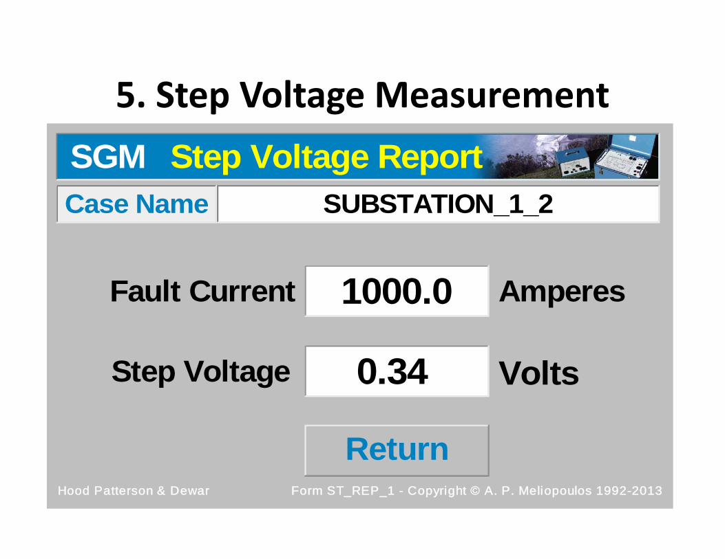
5. Step Voltage Measurement
Case Name SUBSTATION_1_2
Return
1000.0Fault Current Amperes
0.34 Step Voltage Volts
SGM Step Voltage Report
Hood Patterson & Dewar Form ST_REP_1 - Copyright © A. P. Meliopoulos 1992-2013
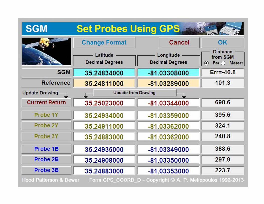
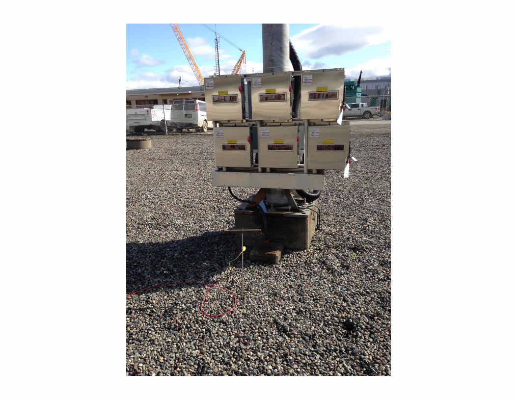
Locating the Current Return Probe