introduction - adaptecdownload.adaptec.com/pdfs/installation_guides/29160n_install_guide.pdf · 1...
TRANSCRIPT

1
INTRODUCTION
With the Adaptec SCSI Card 29160N PCI-Ultra 160 SCSI controller,you can connect up to 15 SCSI devices, such as hard disk drives, scan-ners, CD-ROM drives, and tape drives, to any IBM-compatible comput-er with PCI expansion slots. The following figure shows the SCSI con-nectors on the Adaptec SCSI Card 29160N.
The Adaptec SCSI Card 29160N is designed for computersystem original equipment manufacturers (OEMs). Use this
product with the original computer system designed by the OEM;each OEM tailors their product specifications for their specificdesign needs. Adaptec assumes no responsibility for incompatibilityor consequential damages if you use the Adaptec SCSI Card 29160Nin another computer system. All product support and services are provided by the OEM.
NOTE
This installation guide provides instructions for• Installing the Adaptec SCSI Card 29160N• Setting up SCSI devices• Connecting SCSI devices• Installing driver software
Adaptec SCSI Card 29160N
68-pin Internal Ultra160-LVD Connector
50-pin External High-density Fast/Ultra-SEConnector
50-pin InternalFast/Ultra-SEConnector
512512final.qxd 12/17/99 2:05 PM Page 1

2
Bus Segments on theAdaptec SCSI Card 29160NThe Adaptec SCSI Card 29160N features Adaptec SpeedFlex™ technol-ogy. SpeedFlex technology ensures that you get the most performancefrom your Ultra160 SCSI devices by electronically isolating theUltra160 SCSI segment from the Ultra SCSI segment on the SCSI bus.With the SpeedFlex advantage, the Adaptec SCSI Card 29160N cansupport Ultra160 SCSI devices at speeds up to 160 MBytes/sec whilesimultaneously supporting Ultra (legacy) devices at speeds up to 40MBytes/sec.
If you attach any Wide Ultra or Ultra SCSI devices to theUltra160-LVD connector, the data transfer rate for all devices canrun at various speeds. However, if you attach only Ultra160 andLVD SCSI devices to the Ultra160-LVD connector, all devices willoperate at their maximum possible data transfer rate. That is,Ultra2 devices will operate at a maximum of 80 MBytes/sec andUltra160 devices at a maximum of 160 MBytes/sec.
Ultra SCSI Segment
50-pin High-densityExternal Connector
68-pin Internal Wide Ultra Connector
68-pin Internal Ultra2 Connector
50-pin Internal Ultra Connector
Ultra2 SCSI Segment
AIC-3860
AIC-7890
NOTE
Ultra160-LVDSCSI Segment
68-pin InternalUltra160-LVDConnector
AIC-7892
50-pin InternalFast/Ultra-SEConnector
50-pin ExternalHigh-densityFast/Ultra-SEConnector
Ultra SCSISegment
512512final.qxd 12/17/99 2:05 PM Page 2

3
Discharge any static electricity build-up before handling your SCSIcard by touching a grounded metal object (like the exposed metalparts on the back of your computer).
After you turn off your computer and unplug the power cord, removethe cover from the computer.
Locate an unused PCI expansion slot and remove the expansion slotcover. (The expansion slot must be compliant with PCI Rev. 2.1 orhigher and must support Bus Mastering.) Save the slot cover screw foruse in Step 4.
Computers may have vertical or horizontal expansion slots. Refer toyour computer manual to locate the PCI slots. If your computer is atower model, lay it on its side to allow for easier installation of theAdaptec SCSI Card 29160N.
INSTALLING THE ADAPTEC SCSI CARD 29160N
Turn OFF power to the computer and disconnect thepower cord.
WARNING
STEP 1
STEP 2
STEP 3
PCI Expansion Slots(Typically White or Ivory)
Slot Cover Screw
ExpansionSlot Cover
512512final.qxd 12/17/99 2:05 PM Page 3

4
Insert the Adaptec SCSI Card 29160N into the PCI expansion slot;press down firmly until it clicks into place, then replace the slot coverscrew.
If you refer to the device’s documentation for installationinstructions, be sure to return to this document to continue withinstallation of the software driver.
NOTE
There are several things you need to do to your SCSI devices beforeyou connect them to the Adaptec SCSI Card 29160N:
• Set the SCSI IDs• Set the termination• Connect the power cables.
Since setup can vary from device to device, always refer to the device’sdocumentation for specific instructions.
Below are some guidelines for setting SCSI IDs and termination onyour devices. Refer to the Adaptec SCSI Card 29160N User’s Referencefor additional information on SCSI IDs and termination.
SETTING UP SCSI DEVICES
STEP 4
Adaptec SCSI Card29160N Installed ina PCI Expansion Slot
512512final.qxd 12/17/99 2:05 PM Page 4

5
Check the SCSI IDsThe Adaptec SCSI Card 29160N and each device you connect to itmust have a unique SCSI ID number ranging from 0 to 15.No two devices can have the same number.
The Adaptec SCSI Card 29160N is preset to ID 7 and should not bechanged. If you boot from a SCSI hard disk, make sure the hard diskSCSI ID is set to 0 or 1. Most SCSI hard disks come from the factorypreset to ID 0. The IDs for internal devices are usually set with jumpers;external devices are usually set with a switch on the back of the device.
Terminate the EndsTo ensure reliable communication on the SCSI bus, the device at theend of each cable, or the end of the cable itself, must have a terminatorinstalled (or enabled). Terminators must be removed, or terminationmust be disabled, on devices between the ends of each cable.
512512final.qxd 12/17/99 2:05 PM Page 5

6
You can connect a total of 15 SCSI devices to the Adaptec SCSI Card29160N. Before connecting devices, be sure to also review Setting UpSCSI Devices on page 4.
We recommend that you keep your Ultra160-LVD devicesseparate from your Ultra devices. Connecting an Ultra
device to the Ultra 160-LVD SCSI connector forces the Ultra160-LVD SCSI segment and any attached devices to drop down to UltraSCSI performance levels. (See Bus Segments on the Adaptec SCSICard 29160N on page 2.)
NOTE
Locate the 68-pin internal LVD SCSI cable, as shown below:
CONNECTING SCSI DEVICES
STEP 1
Internal Ultra 160-LVD SCSI Connector (68-pin)Connect internal LVD and Ultra 160-LVD devices using the internalUltra160-LVD connector. To do this, use a 68-pin internal LVD cable,similar to the one shown in Step 1 below. Follow these steps to connectyour internal LVD and Ultra160 devices:
Terminator Connect to Ultra160-LVD andUltra2 Devices
Connect to the AdaptecSCSI Card 29160N
512512final.qxd 12/17/99 2:05 PM Page 6

7
Plug the remaining cable connectors to your internal LVD SCSI orUltra160-LVD devices.
STEP 2
STEP 3
Terminator on Cable
LVD/Ultra160-LVD SCSI Devices
68-pin Internal Ultra160-LVD SCSI Connector
68-pin Internal LVD SCSI Cable
Plug the non-terminated end of the cable to the Ultra160-LVD connector on the Adaptec SCSI Card 29160N.
Internal LVD SCSI or Ultra160 SCSI devices come fromthe factory with termination disabled and cannot be changed.Proper termination is provided by the terminator at the end of theLVD SCSI cable.
NOTE
(Continued on the other side)
512512final.qxd 12/17/99 2:05 PM Page 7
8
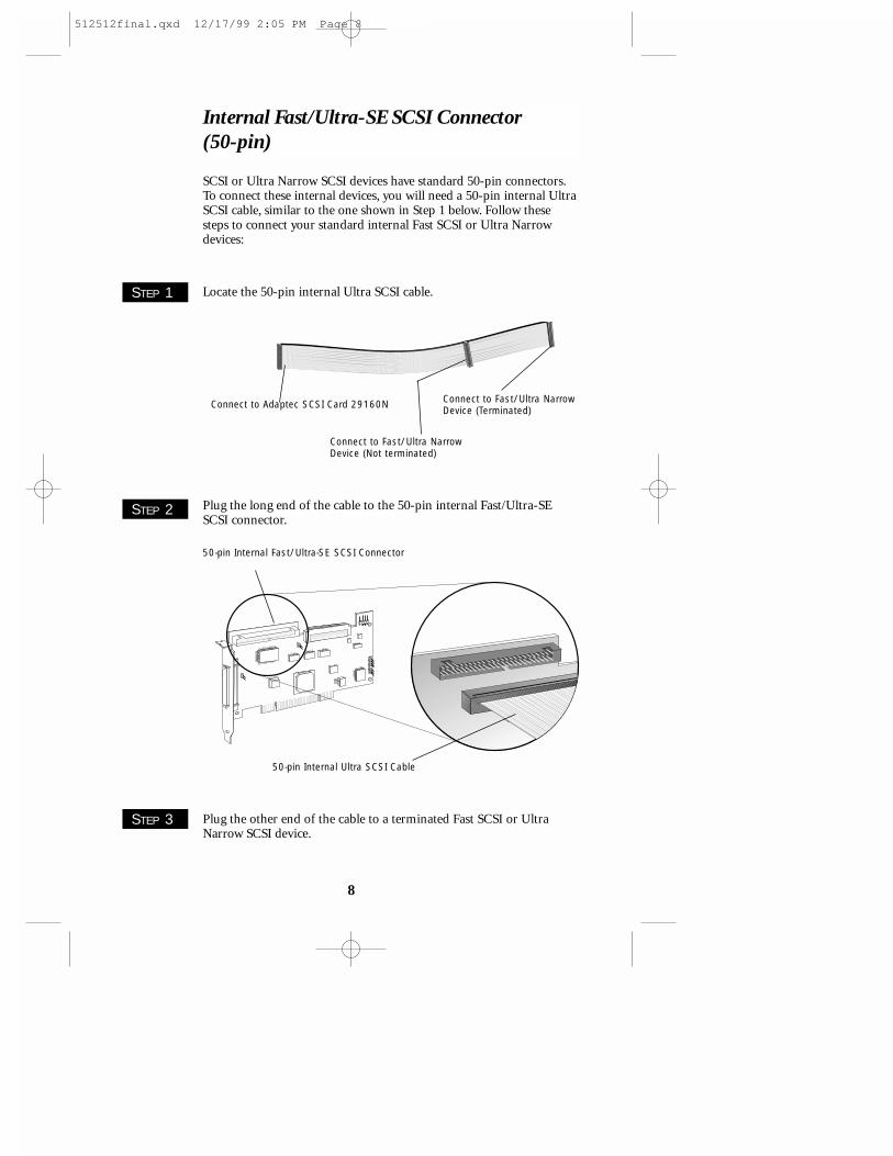
Connect to Adaptec SCSI Card 29160N
Connect to Fast/Ultra NarrowDevice (Not terminated)
Connect to Fast/Ultra NarrowDevice (Terminated)
SCSI or Ultra Narrow SCSI devices have standard 50-pin connectors.To connect these internal devices, you will need a 50-pin internal UltraSCSI cable, similar to the one shown in Step 1 below. Follow thesesteps to connect your standard internal Fast SCSI or Ultra Narrowdevices:
Locate the 50-pin internal Ultra SCSI cable.STEP 1
Plug the long end of the cable to the 50-pin internal Fast/Ultra-SESCSI connector.
Plug the other end of the cable to a terminated Fast SCSI or UltraNarrow SCSI device.
STEP 2
STEP 3
50-pin Internal Fast/Ultra-SE SCSI Connector
50-pin Internal Ultra SCSI Cable
Internal Fast/Ultra-SE SCSI Connector (50-pin)
512512final.qxd 12/17/99 2:05 PM Page 8

9
STEP 2
Connect one end of the external SCSI cable to the 50-pin high-density external connector on the Adaptec SCSI Card 29160N.
Connect the other end of the external SCSI cable to a SCSI connectoron the back of the external SCSI device. If you are installing only oneexternal device, terminate the device and skip to Step 4.
4
4
STEP 1
nal device, you will need to obtain a 50-pin external SCSI cable. Followthese steps to connect your standard external devices:
50-pin External HighDensity SCSI Cable
50-pin High-density Fast/Ultra-SE External Connector
External Fast/Ultra-SE SCSI Connector (50-pin)Use the external Fast/Ultra-SE SCSI connector to connect your stan-dard external SCSI devices that have 50-pin connectors. For each exter-
To connect a second Fast SCSI or Ultra Narrow SCSI device, plug the middleconnector of the cable to the device. Thedevice must not beterminated.
Terminated SCSI Device
STEP 4
Unterminated SCSI Device
512512final.qxd 12/17/99 2:05 PM Page 9

STEP 3
STEP 4
Connect other external devices by connecting each device to the previ-ous one until all devices are connected. The device at the end of thechain must be the only externaldevice that is terminated.
Connect power cables to all internal and external devices and to thecomputer.
Terminated SCSIDevice
10
INSTALLING DRIVER SOFTWARE
To use the Adaptec SCSI Card 29160N, driver softwaremust be installed for your operating system. Installation of
the driver software varies depending on how and where you pur-chased the Adaptec SCSI Card 29160N.
Pre-loaded Adaptec DriversIf the Adaptec SCSI Card 29160N was included as part of a computersystem you purchased, the system already has the appropriate Adaptecdriver pre-installed by the computer manufacturer. No further actionis necessary to install the driver.
NOTE
512512final.qxd 12/17/99 2:05 PM Page 10
To ensure that you have the most current version of the driver available, contact your computer manufacturer.
11
Embedded Adaptec Drivers
SCSI Card 29160N. To load the embedded driver, simply install theAdaptec SCSI Card 29160N and SCSI devices, turn on the devices andthen the computer. The operating system recognizes the Adaptec SCSICard 29160N installed in the computer and then loads the appropriatedriver. Follow any instructions displayed on your screen.
The Windows® 95/98, Windows NT®, NetWare, Linux, and UnixWareoperating systems may have embedded driver support for the Adaptec
Copyright© 1999 Adaptec, Inc. All rights reserved. No part of this publication may be reproduced, storedin a retrieval system, or transmitted in any form or by any means, electronic, mechanical, photo-copying, recording or otherwise, without the prior written consent of Adaptec, Inc., 691 SouthMilpitas Blvd., Milpitas, CA 95035.
TrademarksAdaptec, the Adaptec logo, AHA, and SpeedFlex are trademarks of Adaptec, Inc. which may beregistered in some jurisdictions. Windows, Windows 95/98, and Windows NT are registeredtrademarks of Microsoft Corporation in the U.S. and other countries used under license. Allother trademarks are owned by their respective owners.
NOTE
512512final.qxd 12/17/99 2:05 PM Page 11

12
Regulatory Compliance Statements
Federal Communications Commission Radio Frequency Interference Statement
WARNING: Changes or modifications to this unit not expressly approved by the party responsiblefor compliance could void the user’s authority to operate the equipment.
This equipment has been tested and found to comply with the limits for a Class B digital device,pursuant to Part 15 of the FCC rules. These limits are designed to provide reasonable protectionagainst harmful interference in a residential installation. This equipment generates, uses, and canradiate radio frequency energy, and if not installed and used in accordance with the instructionmanual, may cause harmful interference to radio communications. However, there is no guaranteethat interference will not occur in a particular installation. However, if this equipment does causeinterference to radio or television equipment reception, which can be determined by turning theequipment off and on, the user is encouraged to try to correct the interference by one or more of thefollowing measures:
Reorient or relocate the receiving antenna.
Increase the separation between equipment and receiver.
Connect the equipment to an outlet on a circuit different from that to which the receiver is connect-ed.Consult the dealer or an experienced radio/television technician for help.
Use a shielded and properly grounded I/O cable and power cable to ensure compliance of this unitto the specified limits of the rules.
This device complies with part 15 of the FCC rules. Operation is subject to the following two condi-tions: (1) this device may not cause harmful interference and (2) this device must accept any inter-ference received, including interference that may cause undesired operation.
European Union Compliance Statement
This Information Technology Equipment has been tested and found to comply with the followingEuropean directives:
EMC Directive 89/336/EECEN 50081-1 (1992):EN55022 (1994) Class BEN 50082-1 (1992):
EN61000-4-2 (1998)
EN61000-4-3 (1998)
EN61000-4-4 (1995)
Adaptec, Inc. SCSI Card 29160N
Tested to Comply
With FCC Standards
FOR HOME OR OFFICE USE
512512final.qxd 12/17/99 2:05 PM Page 12

13
Australian/New Zealand Compliance Statement
This device has been tested and found to comply with the lim-its for a Class B digital device, pursuant to the Australian/NewZealand standard AS/NZS 3548 set out by the SpectrumManagement Agency.
Canadian Compliance Statement
This Class B digital apparatus meets all requirements of theCanadian Interference-Causing Equipment Regulations.
Cet appareil numérique de la classe B respecte toutes les exigences du Règlement sur le matérial brouilleur duCanada.
WWee mmoovvee tthhee iinnffoorrmmaattiioonn tthhaattmmoovveess yyoouurr wwoorrlldd.™
R
© 1999, Adaptec, Inc. All rights reserved.Printed in Singapore
Stock No.: 512512-03, Rev. A RAC 9/99(SRC: 512512-00, Ver AA)
512512final.qxd 12/17/99 2:05 PM Page 13

R
ADAPTEC SCSI CARD 29160NULTRA160 SCSI CONTROLLER
INSTALLATION
GUIDE
512512final.qxd 12/17/99 2:05 PM Page 14