interroll lift-up gate installation and operating ...€¦ · interroll lift-up gate rm 8830 safety...
TRANSCRIPT
Installation and Operating InstructionsInterroll Lift-Up GateRM 8830
Version 1.1 (02/2016) en-USTranslation of original instruction manual

Manufacturer's address
Interroll Automation GmbH Dietmar-Hopp-Straße 3 74889 Sinsheim (Germany) Ph.: +49 7261 938 – 0 Fax: +49 7261 938 – 124 www.interroll.com [email protected]
Copyright of installation and operating instructions
The copyright of these installation and operating instructions remains with InterrollAutomation GmbH. The installation and operating instructions contain technicalregulations and drawings which may not be reproduced partially or in full, transmitted byany means, utilized without permission for competitive purposes or disclosed to thirdparties.
IAD - BA - 1881Interroll T. Nr. 1103995
Version 1.1 (02/2016) en-USTranslation of original instruction manual

Interroll Lift-Up Gate RM 8830
Version 1.1 (02/2016) en-USTranslation of original instruction manual
3
Table of contentsIntroduction................................................................................................................................ 5
Notes about working with the installation and operating instructions ............................................ 5Contents of these installation and operating instructions .............................................................. 5Integrated part of the product.............................................................................................................. 5Installation and operating instructions are part of the module.................................................... 5
Warning notices in this document.............................................................................................................. 6Symbols............................................................................................................................................................. 6
Safety ......................................................................................................................................... 7State of the art................................................................................................................................................ 7Intended use .................................................................................................................................................... 7
Field of use.................................................................................................................................................. 7Changes to the module........................................................................................................................... 7
Personnel qualification .................................................................................................................................. 7Operators ................................................................................................................................................... 7Service personnel ..................................................................................................................................... 7Electricians .................................................................................................................................................. 7
Dangers............................................................................................................................................................. 8Safety devices............................................................................................................................................ 8Electricity ..................................................................................................................................................... 8Rotating parts ............................................................................................................................................ 8Parts lying around or falling off ............................................................................................................ 8Risk of injury due to faults during operation ..................................................................................... 8Maintenance intervals ............................................................................................................................. 8
Interfaces to other devices........................................................................................................................... 8Operating modes ........................................................................................................................................... 9
Normal mode............................................................................................................................................. 9Special mode ............................................................................................................................................. 9
Product identification.............................................................................................................. 10Components.................................................................................................................................................. 10Property ......................................................................................................................................................... 10Technical data .............................................................................................................................................. 11Scope of supply ........................................................................................................................................... 11Nameplate .................................................................................................................................................... 12
Transport and storage ............................................................................................................ 13Transport........................................................................................................................................................ 13
Identification of load lifting points..................................................................................................... 13After the delivery................................................................................................................................... 13
Storage .......................................................................................................................................................... 14
Interroll Lift-Up Gate RM 8830
Table of contents
4 Version 1.1 (02/2016) en-USTranslation of original instruction manual
Installation ............................................................................................................................... 15To be observed during installation ......................................................................................................... 15
Torque ....................................................................................................................................................... 15Grounding ............................................................................................................................................... 15Orientation .............................................................................................................................................. 15Anchoring................................................................................................................................................. 16Integration into complete system....................................................................................................... 16
Setting up the module................................................................................................................................ 17Setting up center of gravity position and friction force.................................................................... 18
Setting the correct center of gravity position ................................................................................ 19Setting the friction force....................................................................................................................... 20
Installing the photo cell (optional) ........................................................................................................... 22Installing the conveyor module on the module ................................................................................... 23Installing the handles .................................................................................................................................. 25Installing the universal support ................................................................................................................ 26Installing the photo cell and reflector .................................................................................................... 27Integrating the module in the overall system....................................................................................... 28
Initial startup and operation.................................................................................................. 29Initial startup ................................................................................................................................................. 29Operation...................................................................................................................................................... 31
Before every operation start .............................................................................................................. 31During operation.................................................................................................................................... 31Procedure in case of accident or fault ............................................................................................. 31
Cleaning................................................................................................................................... 32
Maintenance and repair ........................................................................................................ 33Observe the following for maintenance and repair.......................................................................... 33Replacing the plastic guide ....................................................................................................................... 34Replacing the photo cell ............................................................................................................................ 36Maintenance intervals ................................................................................................................................ 38Maintenance and inspection list .............................................................................................................. 38
Troubleshooting....................................................................................................................... 39In case of a fault .......................................................................................................................................... 39Troubleshooting............................................................................................................................................ 39
Spare and wear parts ............................................................................................................ 40Ordering information ................................................................................................................................ 40Spare part drawing RM 8830................................................................................................................. 41RM 8830 spare parts list........................................................................................................................... 41
Decommissioning and disposal ............................................................................................ 42Environmental protection regulations .................................................................................................... 42
Installation declaration .......................................................................................................... 43

Interroll Lift-Up Gate RM 8830
Version 1.1 (02/2016) en-USTranslation of original instruction manual
5
Introduction
Notes about working with the installation and operating instructionsThe Lift-up gate RM 8830 is generally referred to as "module" in this document.
Contents of theseinstallation and operating
instructions
These installation and operating instructions contain important notes and information about thevarious operating phases of the module:
• Transport, assembly and startup• Safe operation, required maintenance tasks, removal of any faults• Spare parts, supplementary accessories
Integrated part of theproduct
The installation and operating instructions describe the module at the time of its initial deliveryafter manufacturing.
In addition to this manual, special contractual agreements and technical documents apply tospecial versions of the module and its additional equipment.
Installation and operatinginstructions are part of the
module
4 To ensure trouble-free and safe operation as well as the settlement of possible warrantyclaims, always read these installation and operating instructions first and observe all theinformation contained herein.
4 Keep the installation and operating instructions close to the module.4 Pass the installation and operating instructions on to any subsequent operator or occupant.
Interroll does not accept any liability for faults or defects due to non-observance of theseinstallation and operating instructions.
If you have any questions after reading the installation and operating instructions, please contactthe Interroll customer service. Contact persons close to you can be found on the Internet under: www.interroll.com/contacts.
Interroll Lift-Up Gate RM 8830
Introduction
6 Version 1.1 (02/2016) en-USTranslation of original instruction manual
Warning notices in this documentThe warning notices refer to risks which may arise while using the module. They are available infour danger levels identified by the signal word:
Signal word Meaning
DANGER Identifies a danger with high risk that can lead to death or serious injury if itis not avoided.
WARNING Identifies a danger with medium risk that can lead to death or serious injuryif it is not avoided.
CAUTION Identifies a danger with low risk that can lead to minor or medium injury if itis not avoided.
NOTICE Identifies a danger that can lead to property damages.
Symbols
This symbol marks useful and important information.
Requirement:R This symbol represents a prerequisite to be met prior to assembly and maintenance work.
4 This symbol marks the steps to be carried out.

Interroll Lift-Up Gate RM 8830
Version 1.1 (02/2016) en-USTranslation of original instruction manual
7
Safety
State of the artThe module has been built to comply with the state of the art. Nevertheless, users may encounterhazards during its use.
Disregarding the notices in this manual may lead to serious injury.4Carefully read the manual and follow its content.
Intended useThe module is intended only for industrial purposes and use in industrial environments andsuitable exclusively as passage to be opened manually in a conveyor section.
The module is an incomplete machine and must be integrated into a complete system prior tooperation.
Field of use The module is dimensioned only for a certain field of use and may not be operated outside ofthese specific limits. For additional information, see the chapter "Technical data".
Any other use is considered inappropriate. Deviating operating conditions require additionalclarifications, a special release of the module and new contractual agreements.
Changes to the module Any modifications that affect the safety are not permitted.
Personnel qualificationUnqualified personnel cannot recognize risks and, as a result, is subject to greater dangers.
4 Authorize only qualified personnel with the activities described in these installation andoperating instructions.
4 The operating company must ensure that the personnel follows locally applicable regulationsand rules during their work with regard to safety and dangers.
The following target groups are addressed in these installation and operating instructions:
Operators Operators have been instructed in the operation and cleaning of the module and follow thesafety guidelines.
Service personnel The service personnel features a technical training and performs the maintenance and repairtasks.
Electricians Persons working on electrical installations must have the pertinent technical training.

Interroll Lift-Up Gate RM 8830
Safety
8 Version 1.1 (02/2016) en-USTranslation of original instruction manual
Dangers
The following list informs you about the various types of danger or damage that may occurwhile working with the module.
Safety devices 4 Perform any maintenance and repair work on the module only in de-energized state andensure that it cannot be started accidentally.
4 In the passage area of persons or if persons can reach between transported materials,additional protective measures may apply.
4 Do not remove protective covers or housing.4 Regularly check the safety devices.
Electricity 4 Reach into the module only if the module is de-energized.
Rotating parts 4 Never wear loose clothing.4 Never wear jewelery, such as necklaces or bracelets.4 If you have long hair, always wear a hair net.
Parts lying around orfalling off
4 Remove equipment or material which is not required from the workspace.4 Wear safety shoes.4 Specify and monitor careful placement of the goods on the conveyor.
Risk of injury due to faultsduring operation
4 Regularly check the module for visible damage.4 Immediately shut down the module and ensure that it cannot be started accidentally in case
of:fire vapors, unusual, noise, blocked or defective conveyor belt, defective supports, sideguides or accessory devices, unauthorized removal of safety covers and with a defectivesuspension.
4 Immediately determine the cause of the fault by qualified personnel.4 Immediately remove any escaping gear oil.4 Do not step on the module during operation.
Maintenance intervals 4 Regularly perform maintenance and inspection work.4 Use only OEM spare parts.
Interfaces to other devicesNew hazardous positions may occur while integrating the module into a complete system. Thesepositions are not part of this manual and have to be analyzed during the assembly and startupof the complete system.
4 When combining the module with other modules or machinery, check for new hazardsbefore startup. In particular, observe the infeed point at the deflection shaft.
4 Additional constructive measures may be required.

Interroll Lift-Up Gate RM 8830
Safety
Version 1.1 (02/2016) en-USTranslation of original instruction manual
9
Operating modes
Normal mode The module is installed at the customer in a complete system and operated as part of the system.
Special mode Special operation refers to all operating modes which are required to guarantee and maintainregular operation.
Special operating mode Explanation Comment
Transport/Storage Loading and unloading, transport and storage -
Assembly/Initial start-up Installation at the end customer and performing the test run -
Cleaning External cleaning without removing protective devices When de-energized
Maintenance/Repairs Maintenance and inspection tasks When de-energized
Troubleshooting Troubleshooting in the event of a fault -
Fault elimination Eliminating the fault When de-energized
Shutdown Removing from the complete system When de-energized
Disposal Removing from the complete system and disassembly When de-energized

Interroll Lift-Up Gate RM 8830
10 Version 1.1 (02/2016) en-USTranslation of original instruction manual
Product identification
Components
1 2 3 4 5
8
7
6
RM 8830
1 Plastic guide 5 Roller conveyor2 Reflector 6 Gripper plates3 Photo cell 7 Lever system4 Counterweight crossbar 8 Base
PropertyThe lift-up gate swivels upward to provide a walkway, or access from one side of the conveyorto the other. This allows access to the rear of the conveyor, and the ability to plan quickerescape routes, in case of an emergency. The pivoting movement is operated by an innovativerotary mechanism.

Interroll Lift-Up Gate RM 8830
Product identification
Version 1.1 (02/2016) en-USTranslation of original instruction manual
11
Technical data
Lift-Up Gate RM 8830
Max. load capacity 100 kg (incl. fitted module)
Overall height 645 mm (to T.O.R.)
Ambient temperature -5 to +40 °C
Incline/decline Not suitable
Between frames 300 to 840 mm
Module length of conveyor module 1000 to 1440 mm
Channel width Module length to 220 mm
Noise level Leq ≤ 70 dB(A)
Scope of supplyThe lift-up gate is delivered completely assembled. The scope of supply includes:
• Rack including base with plastic guides, lever system, counterweights• Photo cell and reflector• Handles
The mounted conveyor module has to be ordered separately.

Interroll Lift-Up Gate RM 8830
Product identification
12 Version 1.1 (02/2016) en-USTranslation of original instruction manual
Nameplate
8
3
1
2
4
5
6
7
Nameplate
1 Arrow in transport direction 5 Year of construction2 Type designation 6 Company address3 Machine no. 7 Weight in kg4 Layout item no. 8 Level
The information on the nameplate is used to identify the conveyor. The type designation isrequired to use the conveyor according to its intended use.
The nameplate is located close to the right stand in transport direction.

Interroll Lift-Up Gate RM 8830
Version 1.1 (02/2016) en-USTranslation of original instruction manual
13
Transport and storage
Transport
WARNINGRisk of injury during transport
4 Fix the module securely and slip-proof for the transport.4 Ensure that the lifting device (crane, fork lift, etc.) is rated for the weight of the module.4 Ensure that no persons are located under the suspended load while lifting and moving the
module.
Additional information about the transport are located on an information sheet thataccompanies the motor.
4 Data about weight and requirements for loading capacity and lifting tackle are located onthe information sheet.
4 Remove any persons from the danger zone.4 Wear safety shoes.4 Check the correct fastening for the transport.
The load lifting points are marked on the module.
If the module is mounted to a conveyor module, the load lifting points are marked on theconveyor module.
Identification of loadlifting points
After the delivery 4 Inspect module for transport damages.4 Immediately notify the carrier and manufacturer in case of damages to avoid losing any
claims for compensation.

Interroll Lift-Up Gate RM 8830
Transport and storage
14 Version 1.1 (02/2016) en-USTranslation of original instruction manual
Storage
WARNINGRisk of injury due to improper storage
4 Do not stack modules. Do not place any other objects on the module.4 Check module for stability.
4 If the module is not immediately placed in operation, store it at a location protected againsthumidity and dust.

Interroll Lift-Up Gate RM 8830
Version 1.1 (02/2016) en-USTranslation of original instruction manual
15
Installation
WARNINGRisk of injury due to improper assembly
4 Mechanical assembly tasks should be performed only by service personnel. Observe thesafety information.
4 Electrical assembly tasks should be performed only by authorized electricians. Observe thesafety information.
4 Carefully install all terminals and connections, such as cables, hoses and pipework, and checkfor correct fit.
The module is delivered to the location site as a pre-assembled unit and only has to becombined with a roller conveyor and integrated into a system on site. The following steps arerequired for the installation and integration in a complete system:
• Set up the module, See "Setting up the module", page 17• Set up center of gravity position and friction force, See "Setting up center of gravity position
and friction force", page 18• Install the photo cell, See "Installing the photo cell (optional)", page 22 (optional)
The conveyor module is typically already installed on the lift-up gate. If the conveyor module isnot yet installed, the respective steps must be performed:
• Install the conveyor module on the lift-up gate, See "Installing the conveyor module on themodule", page 23
• Install the handles on the conveyor module, See "Installing the handles", page 25
In principle, photo cell and reflector are already pre-assembled. If one of the followingcomponents is not installed, the respective steps must be performed:
• Install the universal support, See "Installing the universal support", page 26• Install photo cell and reflector, See "Installing the photo cell and reflector", page 27
To be observed during installation
Torque When tightening screws and nuts, always observe the standard tightening torque, unlessspecifically indicated otherwise. Standard screw lockers should be replaced as needed.
Grounding During the installation of the module, its grounding must be observed. Among other things, theprofile connectors are used for this purpose. If no profile connector is used for connecting themodules, alternate measures must be taken.
Orientation 4 Align the module at the height-adjustable feet of the support. The decisive item for aligningthe modules is the roller top edge (for roller conveyors) or the belt top edge (for beltconveyors).Secure the adjusted height. Use suitable tools for the alignment (spirit level or rotation laser).
4 During the alignment of the module, ensure that no moving parts are touching.
Interroll Lift-Up Gate RM 8830
Installation
16 Version 1.1 (02/2016) en-USTranslation of original instruction manual
Anchoring 4 Anchor or fasten the module torsion-free, e.g. to the floor or adjacent components.
Integration into completesystem
4 When integrating the module into the complete system, consider possible danger spots,particularly infeed locations and interfaces.

Interroll Lift-Up Gate RM 8830
Installation
Version 1.1 (02/2016) en-USTranslation of original instruction manual
17
Setting up the module
CAUTIONRisk of injury when lifting heavy loads
4 During the installation and replacement of conveyor modules or heavy spare parts, work inpairs or use a suitable carriage.
CAUTIONRisk of crushing from rotating parts
4 Before any assembly and maintenance work, the respective devices must be decommissionedand disconnected from the voltage supply.
4 Secure the respective devices against accidental activation.4 When integrating the module into a complete system, consider possible danger spots,
particularly infeed locations and interfaces.
4 Align the conveyor module so that the side frames of the conveyor module are aligned withthe side frames of the adjacent conveyor modules. During alignment, ensure that no movingparts are touching.
4 Fasten the module torsion-free, e.g. anchored to the floor. Use a spirit level or leveling devicefor this purpose.
Interroll Lift-Up Gate RM 8830
Installation
18 Version 1.1 (02/2016) en-USTranslation of original instruction manual
Setting up center of gravity position and friction forceThe force required for swiveling the conveyor module depends on the following settings:
• Center of gravity position• Friction force between the guide elements
The center of gravity position is set in the first step, See "Setting the correct center of gravityposition", page 19. In the second step, if required, the friction force setting is changed, See"Setting the friction force", page 20.

Interroll Lift-Up Gate RM 8830
Installation
Version 1.1 (02/2016) en-USTranslation of original instruction manual
19
Setting the correct centerof gravity position
3 121 4
Lift-up gate with counterweight
1 Countersunk screw 3 Main weight2 Counterweight 4 Nut
The lift-up gate with the installed conveyor module has the correct center of gravity position ifthe force for opening and the force for closing the conveyor module are almost equal in size. Toset the center of gravity position, the main weight (3) is installed at the installed conveyor. Ifnecessary, additional counterweights (2) are installed at the tensioning plates of the lift-up gate.
4 The main weight is installed on the side frame of the conveyor module from below using 4countersunk screws (1) and nuts (4).
4 If necessary, install additional counterweights (2) with 2 screws on the tensioning plates.

Interroll Lift-Up Gate RM 8830
Installation
20 Version 1.1 (02/2016) en-USTranslation of original instruction manual
Setting the friction force1 2
Plastic guide and guide pin
1 Plastic guide 2 Disk at guide pin
The friction force between the guide elements is determined by the compressive stress betweenthe disk (2) at the guide pins and the plastic guide (1).
Interroll Lift-Up Gate RM 8830
Installation
Version 1.1 (02/2016) en-USTranslation of original instruction manual
21
C
X
5
3 2
1
2
3
1
4
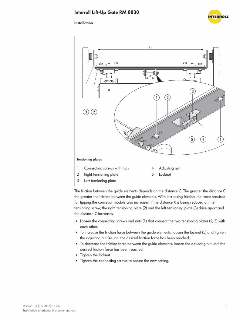
Tensioning plates
1 Connecting screws with nuts 4 Adjusting nut2 Right tensioning plate 5 Locknut3 Left tensioning plate
The friction between the guide elements depends on the distance C. The greater the distance C,the greater the friction between the guide elements. With increasing friction, the force requiredfor tipping the conveyor module also increases. If the distance X is being reduced on thetensioning screw, the right tensioning plate (2) and the left tensioning plate (3) drive apart andthe distance C increases.
4 Loosen the connecting screws and nuts (1) that connect the two tensioning plates (2, 3) witheach other.
4 To increase the friction force between the guide elements, loosen the locknut (5) and tightenthe adjusting nut (4) until the desired friction force has been reached.
4 To decrease the friction force between the guide elements, loosen the adjusting nut until thedesired friction force has been reached.
4 Tighten the locknut.4 Tighten the connecting screws to secure the new setting.

Interroll Lift-Up Gate RM 8830
Installation
22 Version 1.1 (02/2016) en-USTranslation of original instruction manual
Installing the photo cell (optional)If the lift-up gate is open, this is indicated by a photo cell signal. When a 24 V roller conveyor isused, the signal automatically switches off the conveyor segment in front of the lift-up gate. Forthis purpose, the photo cell is connected to the control system of the adjacent conveyor module.
The photo cell cannot be installed until the lift-up gate with the conveyor module has beencompletely installed.
Requirement:R The module is out of operation.
4 Connect the photo cell to the control system of the adjacent module with a cable.4 Check whether both LEDs are lit.4 If the yellow LED flashes, position reflector and photo cell to each other.
LED green LED yellow Meaning
On Off Photo cell is operational. No signal from reflector.
On On Photo cell is correctly adjusted. Light beam is well reflected.
On Flashing Photo cell is operational. Weak signal. Reflector is dirty, damaged or not correctly adjusted.

Interroll Lift-Up Gate RM 8830
Installation
Version 1.1 (02/2016) en-USTranslation of original instruction manual
23
Installing the conveyor module on the module
40
5
1
Conveyor module and lift-up gate RM 8830
1 Tensioning plate
CAUTIONRisk of injury when lifting heavy loads
4 During the installation and replacement of conveyor modules or heavy spare parts, work inpairs or use a suitable carriage.
4 Remove the side covers of the conveyor module.4 Place the conveyor module on the lift-up gate. In this process, ensure that the edge of the
conveyor module protrudes 5 mm beyond the edge of the tensioning plates (1).
Interroll Lift-Up Gate RM 8830
Installation
24 Version 1.1 (02/2016) en-USTranslation of original instruction manual
3
2
1
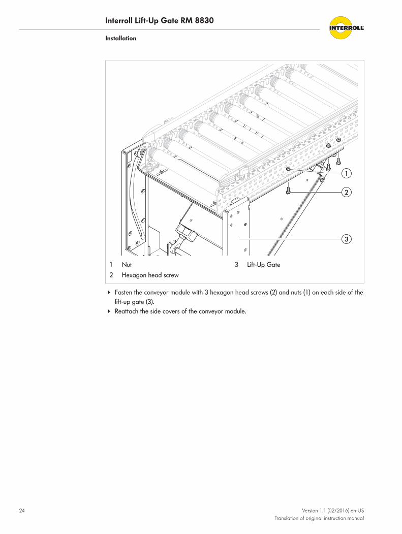
1 Nut 3 Lift-Up Gate2 Hexagon head screw
4 Fasten the conveyor module with 3 hexagon head screws (2) and nuts (1) on each side of thelift-up gate (3).
4 Reattach the side covers of the conveyor module.

Interroll Lift-Up Gate RM 8830
Installation
Version 1.1 (02/2016) en-USTranslation of original instruction manual
25
Installing the handlesTwo handles are attached to the conveyor module. They are used to lift up the lift-up gate andas support surfaces for the following conveyor module.
54
1 2 1
3
3
4
Handle plates with handles on conveyor module
1 Countersunk screw 3 Serrated flange bolt2 Handle plate 4 Side cover
4 Remove the side cover.4 Fasten the handle plate to the side frames of the conveyor module using 2 countersunk
screws at the top and 2 serrated flange bolts on the bottom as well as 4 nuts. In doing so,ensure that the handle plate protrudes approx. 54 mm beyond the conveyor module.
4 Shorten the side cover accordingly and reattach it.

Interroll Lift-Up Gate RM 8830
Installation
26 Version 1.1 (02/2016) en-USTranslation of original instruction manual
Installing the universal support
1 2 3
4
2
Installing the universal support on the conveyor module
1 Nut 3 Serrated flange bolt2 Universal support 4 End cap
The universal support (2) is installed laterally on the side frame of the conveyor module.
4 Remove end cap (4) from the side frame.4 Fasten the universal support in the upper row of holes of the side frame using 2 serrated
flange bolts (3) and nuts (1).4 Push the end cap into the side frame.
Interroll Lift-Up Gate RM 8830
Installation
Version 1.1 (02/2016) en-USTranslation of original instruction manual
27
Installing the photo cell and reflectorThe photo cell is delivered as a finished unit. It is installed on the conveyor module using amounting plate and a universal support.
1
3
2
2
4
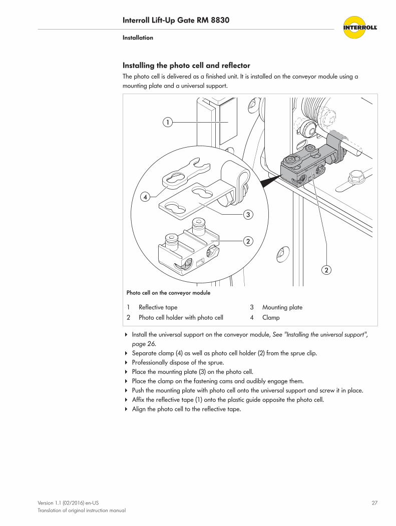
Photo cell on the conveyor module
1 Reflective tape 3 Mounting plate2 Photo cell holder with photo cell 4 Clamp
4 Install the universal support on the conveyor module, See "Installing the universal support",page 26.
4 Separate clamp (4) as well as photo cell holder (2) from the sprue clip.4 Professionally dispose of the sprue.4 Place the mounting plate (3) on the photo cell.4 Place the clamp on the fastening cams and audibly engage them.4 Push the mounting plate with photo cell onto the universal support and screw it in place.4 Affix the reflective tape (1) onto the plastic guide opposite the photo cell.4 Align the photo cell to the reflective tape.

Interroll Lift-Up Gate RM 8830
Installation
28 Version 1.1 (02/2016) en-USTranslation of original instruction manual
Integrating the module in the overall system
Use of an additional roller to connect gate flap with adjacent conveyor
When integrating the gate flap in a complete system, the following distances to the adjacentconveyors must be observed:- 90 mm before the gate flap (on the side with the lever system) - 10 mm after the gate flap (on the side of the gripper plates)
Requirement:R Gate flap and adjacent roller conveyor are aligned with each other.
4 Ensure that the gap between gate flap and adjacent roller conveyor measures 90 mm at thefront or 10 mm at the rear.
4 Install an additional roller between gate flap and adjacent roller conveyor and close the gap.Roller is fastened at the adjacent roller conveyor with both mounting brackets.

Interroll Lift-Up Gate RM 8830
Version 1.1 (02/2016) en-USTranslation of original instruction manual
29
Initial startup and operation
Initial startup
WARNINGRisk of injuries due to incorrect handling
4 Check electrical connections and protective devices.4 Remove the materials from the module.4 Remove unauthorized persons from the danger zone.4 Wear safety shoes and work clothing.
CAUTIONRisk of crushing
4 Remove rubber buffers in the plastic guide before the initial startup.
The module has been checked at the factory.
The rubber buffer is used solely to secure the module during transport and installation. It must beremoved together with the holder before the initial startup.

Interroll Lift-Up Gate RM 8830
Initial startup and operation
30 Version 1.1 (02/2016) en-USTranslation of original instruction manual
1 2
Rubber buffer with holder
1 Rubber buffer 2 Holder
4 Create a horizontal support for the lift-up gate with the installed conveyor module with thehelp of the handle plates and the adjacent conveyor module.
4 Ensure that the lift-up gate is firmly anchored to the floor.4 Loosen hexagon head screws of the holder (2).4 Fold up the conveyor module.4 Remove rubber buffer (1) on both sides together with the holder.
Interroll Lift-Up Gate RM 8830
Initial startup and operation
Version 1.1 (02/2016) en-USTranslation of original instruction manual
31
Operation
Before every operationstart
4 Check the module for visible damage.4 Ensure that all safety devices operate flawlessly.4 Ensure that only authorized personnel is in the operating area of the module.4 Remove equipment or material which is not required from the operating area.4 Guide and monitor correct placement of the goods on the conveyor.
During operation
WARNINGDanger from rotating parts
Crushing and serious injuries from parts of the body and clothing being pulled into the module!
4 Do not remove the protective covers.4 Wear close-fitting clothing, avoid jewelry and bands/ribbons.4 If you have long hair, always wear a hair net.
4 If materials are jammed between side guides, switch off the module and ensure that it cannotbe started accidentally, then remove the fault.
Procedure in case ofaccident or fault
4 Stop the module and ensure that it cannot be started accidentally.4 In case of an accident: Render first aid and make an emergency call if necessary.4 Inform qualified personnel.4 Have the fault removed by qualified personnel.4 Restart the module only after this has been approved by qualified personnel.

Interroll Lift-Up Gate RM 8830
32 Version 1.1 (02/2016) en-USTranslation of original instruction manual
Cleaning
WARNINGRisk of injuries due to incorrect handling
4 Only perform cleaning work on the module after you have switched off the power. Switchoff the voltage supply and ensure that it cannot be started accidentally.
4 Do not remove protective devices.4 Wear safety shoes and close-fitting work clothing.
4 Clean belts only dry.4 For the remaining parts of the module, use only suitable cleaning agents (water-soluble, free
of phosphate, silicone and potassium, non-acidic). Observe the manufacturer's instructions.

Interroll Lift-Up Gate RM 8830
Version 1.1 (02/2016) en-USTranslation of original instruction manual
33
Maintenance and repair
Observe the following for maintenance and repair
WARNINGRisk of crushing and injuries
4 Ensure that the personnel involved in maintenance and repair have secure footing andsufficient room to move.
4 Mechanical maintenance and repair work may only be performed by service personnel.Observe the safety information.
4 Electrical maintenance and repair work should be performed only by authorized electricians.Observe the safety information.
4 Observe the weight of the module (see nameplate); if necessary work in pairs.4 Use suitable loading and lifting equipment. Secure the module against falling or tipping.
When tightening screws and nuts, always observe the standard tightening torque, unlessspecifically indicated otherwise. Standard screw lockers should be replaced as needed.
4 Always have work on electrical equipment carried out by authorized electricians.4 Set up warning signs that indicate maintenance and repair work.4 Block off the area around the module.4 Inform persons who have to enter the blocked-off area about the risks.
Interroll Lift-Up Gate RM 8830
Maintenance and repair
34 Version 1.1 (02/2016) en-USTranslation of original instruction manual
Replacing the plastic guide
1 2 3 4
6
5
1
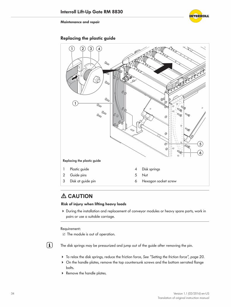
Replacing the plastic guide
1 Plastic guide 4 Disk springs2 Guide pins 5 Nut3 Disk at guide pin 6 Hexagon socket screw
CAUTIONRisk of injury when lifting heavy loads
4 During the installation and replacement of conveyor modules or heavy spare parts, work inpairs or use a suitable carriage.
Requirement:R The module is out of operation.
The disk springs may be pressurized and jump out of the guide after removing the pin.
4 To relax the disk springs, reduce the friction force, See "Setting the friction force", page 20.4 On the handle plates, remove the top countersunk screws and the bottom serrated flange
bolts.4 Remove the handle plates.
Interroll Lift-Up Gate RM 8830
Maintenance and repair
Version 1.1 (02/2016) en-USTranslation of original instruction manual
35
4 Fold down the conveyor module until both guide pins (2) with the disk springs (4) and thewasher (3) slide out of the plastic guides (1) at the front.
4 Position the conveyor module so that the plastic guide can be uninstalled without anyproblems; support as necessary.
4 Loosen all screws (6) that fasten the plastic guide to the housing. To do so, hold the nuts (5)on the inside of the base.
4 Remove the defective plastic guide.4 Install a new plastic guide with screws and nuts.4 Fold up the conveyor and reinsert the pins together with disk springs and washer into the
plastic guides.4 Install the handle plates, See "Installing the handles", page 25.4 Check ease of movement of pins in the groove. If necessary, loosen the screws again and
correct the gap width.
Interroll Lift-Up Gate RM 8830
Maintenance and repair
36 Version 1.1 (02/2016) en-USTranslation of original instruction manual
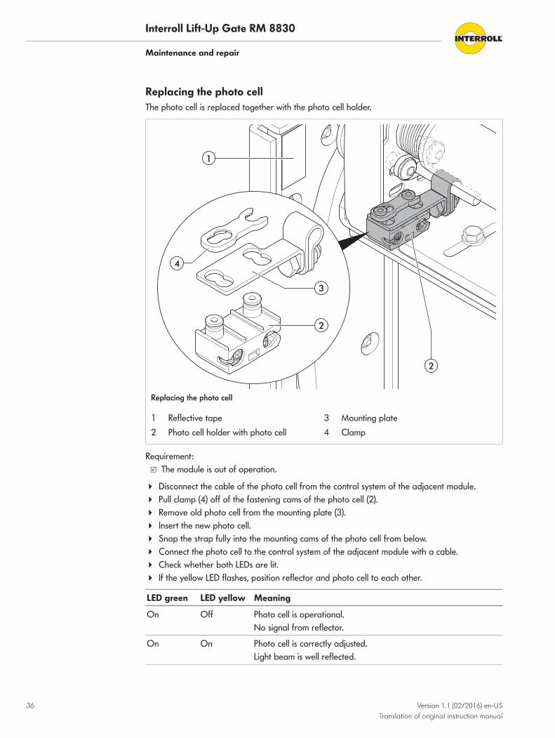
Replacing the photo cellThe photo cell is replaced together with the photo cell holder.
1
3
2
2
4
Replacing the photo cell
1 Reflective tape 3 Mounting plate2 Photo cell holder with photo cell 4 Clamp
Requirement:R The module is out of operation.
4 Disconnect the cable of the photo cell from the control system of the adjacent module.4 Pull clamp (4) off of the fastening cams of the photo cell (2).4 Remove old photo cell from the mounting plate (3).4 Insert the new photo cell.4 Snap the strap fully into the mounting cams of the photo cell from below.4 Connect the photo cell to the control system of the adjacent module with a cable.4 Check whether both LEDs are lit.4 If the yellow LED flashes, position reflector and photo cell to each other.
LED green LED yellow Meaning
On Off Photo cell is operational. No signal from reflector.
On On Photo cell is correctly adjusted. Light beam is well reflected.

Interroll Lift-Up Gate RM 8830
Maintenance and repair
Version 1.1 (02/2016) en-USTranslation of original instruction manual
37
LED green LED yellow Meaning
On Flashing Photo cell is operational. Weak signal. Reflector is dirty, damaged or not correctly adjusted.

Interroll Lift-Up Gate RM 8830
Maintenance and repair
38 Version 1.1 (02/2016) en-USTranslation of original instruction manual
Maintenance intervals
If maintenance is not performed according to schedule, it may lead to damages and failures. Ifmaintenance intervals are not followed, the warranty will be void.
All bearings of the module feature a life-time lubrication and are maintenance-free within theoperating parameters.
Maintenance and inspection list
Component Interval Tasks/check Work to beperformed
Performedby
Completemodule
Weekly General visual andacoustic remote check
Completemodule
Annually Check screw connections Tighten toapplicablestandard asrequired
Completemodule
Every 6 months Check for cleanliness Clean as required
Completemodule
Every 6 months Lightly spray guide railswith silicone spray
Interroll Lift-Up Gate RM 8830
Version 1.1 (02/2016) en-USTranslation of original instruction manual
39
Troubleshooting
In case of a fault
DANGERDanger - electrocution
4 Only perform maintenance and repair work after you have switched off the power.4 Faults on electrical equipment may be removed only by a trained electrician!
Requirement:R The danger spots on the module are covered by protective plates and other protective
devices.
4 Immediately de-energize the complete conveyor system and ensure that it cannot be startedaccidentally.
4 Remove material and blocking objects.4 Before switching it on again, ensure that no persons are at risk.4 Professionally dispose of any gear oil that as leaked out. Have the motor replaced by
qualified personnel if necessary.
Troubleshooting
Fault Cause Remedy
Lift-up gate is not balancedacross the entire swivelmovement.
Center of gravity position ofconveyor module is not in thecorrect position.
Correct center of gravityposition with counterweights.
Movement of lift-up gate issluggish.
Lubrication is insufficient. Spray guide rails with siliconespray.
Compression elements aretensioned too much.
Slightly relax the compressionelements.
Movement of lift-up gate is toolight.
Compression elements are nottensioned enough.
Slightly retension thecompression elements.
Interroll Lift-Up Gate RM 8830
40 Version 1.1 (02/2016) en-USTranslation of original instruction manual
Spare and wear partsAll spare and wear parts are available from Interroll. Maintenance and repair work may beperformed only by qualified personnel. Interroll offers training sessions about requiredmaintenance and repair tasks upon request.
Ordering informationOrdering spare and wear parts requires the exact identification of the module, Nameplate.
The following information is required for an order:• Machine number• Type• Item number of spare parts list• Designation• Comment
For additional information about the spare parts portfolio, please contact your supplier.

Interroll Lift-Up Gate RM 8830
Spare and wear parts
Version 1.1 (02/2016) en-USTranslation of original instruction manual
41
Spare part drawing RM 8830
42 1 3
1
2
Lift-Up Gate RM 8830
RM 8830 spare parts listS = spare part, W = wear part, T = tool
Type: 8830
Item no. Designation Comment S/W/T
1 Disk spring S
2 Plastic guide S
3 Photo cell with holder S
4 Reflective tape S

Interroll Lift-Up Gate RM 8830
42 Version 1.1 (02/2016) en-USTranslation of original instruction manual
Decommissioning and disposal4 When disposing the motor oil, observe the disposal documents of the motor manufacturer.4 The packaging must be recycled to provide environmental relief.
Environmental protection regulationsFor all work on and with the module, the legal regulations concerning waste avoidance andproper disposal and recycling must be followed.
NOTICESubstances with a water hazard class, such as greases and oils, hydraulic oils,coolants or cleaning agents with solvents may not be allowed to come into contactwith the ground or reach the sewer system!
4 Store, transport, catch and dispose these substances in suitable containers!4 Observe the notices on the supply containers.4 Observe any additional national regulations.

Interroll Lift-Up Gate RM 8830
Version 1.1 (02/2016) en-USTranslation of original instruction manual
43
Installation declarationIn accordance with the EC Machinery Directive 2006/42/EC, Appendix II 1 B.
The manufacturer:Interroll Automation GmbH Dietmar-Hopp-Straße 3D-74889 Sinsheim, Germany
herewith declares that the conveyor module described below is an incomplete machine inaccordance with the EU Machinery Directive:
• Lift-Up Gate RM 8830
Important Note! The incomplete machine may only be put into operation if it has beendetermined that the overall machine/system, into which the incomplete machine is to be installed,meets the requirements of this directive.
The following safety requirements as stated in Appendix I have been applied:• 1.1.2, 1.1.3, 1.1.5, 1.1.6, 1.3.1, 1.3.2, 1.3.3, 1.3.4, 1.3.7, 1.3.8, 1.4.1, 1.5.4, 1.5.8, 1.5.9,
1.6.1, 1.6.4, 1.7.4
The special technical documents mentioned in Appendix VII B have been prepared and will besent to the responsible authority if necessary. The transmission is done electronically.
Responsible for EC documentation: Interroll Automation GmbH, Dietmar-Hopp-Straße 3,D-74889 Sinsheim, Germany
Applicable EC Directives:• Machinery Directive 2006/42/EC• EMC Directive 2014/30/EU
Applicable harmonized standards:• EN ISO 12100:2011-03 "Safety of machinery - Basic concepts - risk assessment and
reduction"• EN ISO 13857:2008-06 "Safety of machinery - Safety distances to prevent hazard zones
being reached by upper and lower limbs"• EN 349:2008-09 "Safety of machinery - Minimum gaps to avoid crushing of parts of the
human body"• EN 60204-1:2007-06 "Safety of machinery - Electrical equipment of machines - Part 1:
General requirements"
Sinsheim, dated
Robert Lugauer(Manager)

For your local contacts please visitinterroll.com/contacts
©copyright
Version 1.1 (02/2016)Translation of original instruction manual