installation manual: toyota rav4 power lift gate · pdf fileinstallation manual: toyota rav4...
TRANSCRIPT

Page 1 of 12
Installation Manual: Toyota RAV4Power Lift Gate System

Page 2 of 12
NOTE: Installation Precaution
1. It is recommended to have this product installed by a professional to avoid damage caused by im-proper installation.
2. Do not attempt to disassemble or modify any components included within the kit. Unapproved modi-fications or evidence of tampering will void any warranty included with the product.
3. Before installation, inspect the vehicle's controls and interior/exterior for any damage or malfunc-tioning components. Report any damage or non conformities to the customer prior to installing the product.
4. Inspect the factory lift gate for proper operation and function of lights before installing this product. Improper opening or closing of the lift gate may interfere with the functionality of the Power Lift Gate System.
5. It is recommended to remove or cover any item of clothing (belt buckles, jeans rivets, buttons, etc) prior to installation of this accessory to prevent damage incurred to the vehicle during the installation.
6. Interior panels that have been removed should be set aside somewhere safe during the installation process to avoid damage.
7. When routing and securing wiring harnesses, care should be exercised to avoid any hot, sharp, or moving objects in the vehicle such as steering column, pedals, dash bracing, HVAC components, etc.
8. Do not deviate from methods of installation in this document. Any damage caused by improper wire routing, incorrect connections, wiring, etc. is not covered under the warranty.
9. Disconnect the negative (-) battery terminal before proceeding to installation. Wait at least 2 min-utes after disconnecting the negative (-) battery terminal to disable the SRS and other systems in the vehicle. Any damage caused from failure to disconnect the battery is not covered under the warranty.
10. After installation, you must manually close the lift gate to initialize the Power Lift Gate System.

Page 3 of 12
Kit Details
Electronic Locking Mechanism
Reverse Light
Outside Latch Button
LOCK ILL+ KEY
3 Pin Male &
Female
2 Pin Male &
Female
3 Pin Male &
Female
Component Locator
6 Pin Male
Button Cup
1 2 3
6 Pin Male
10 Pin Male
SD Card Slot
Control Box
2 1 3 4 1 2 3
Call Voxx Support for technical assistance:
1-800-645-4994 9 AM
– 6 PM (EST - Eastern) M
onday – Friday
RAV4 Liftgate System Layout
2 Pin Black Buzzer
Page 4 of 12
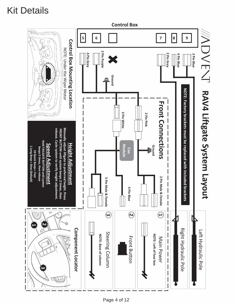
Kit DetailsControl Box
RAV4 Liftgate System Layout
Left Hydraulic Pole
Main Pow
er
NO
TE: Left of fuse box
Component Locator
2 Pin Grey
2 Pin Blue
Front Button
4 Pin Grey
2 Pin Purple
9 8 7 6 5
Right Hydraulic Pole
2 Pin Male &
Female
3 Pin White
2 Pin Pink
Can M
odule 4 Pin Blue
Steering Column
NO
TE: Base of column
5 Pin Male &
Female
Ground
1 2 3
4 Pin Blue
For technical support please call Voxx Support:
1-800-645-4994
9 AM – 6 PM
(EST - Eastern) M
onday – Friday
Ground
Control Box Mounting Location
NO
TE: Under the W
iper Motor Front Connections
Height Adjustment
Manually adjust liftgate to preferred height. Press
FRON
T BUTTO
N until system
beeps 2 times, then
release. Cycle system to verify height adjustm
ent.
Speed Adjustment
Hold TAILGATE BU
TTON
until system
beeps 5 times, then release
10 Quick Beeps = Fast
1 Long Beep = Slow (Default)
1
2 3
NO
TE: Factory brackets must be replaced w
ith included brackets
Page 5 of 12
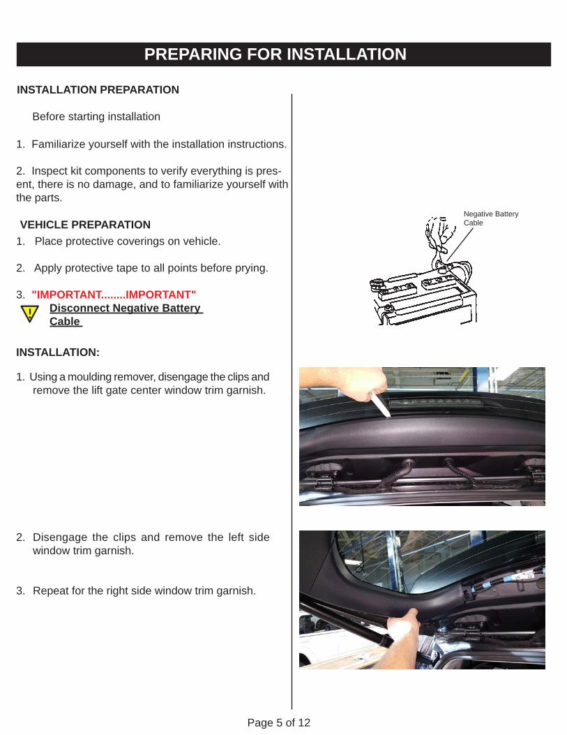
INSTALLATION PREPARATION
Before starting installation
1. Familiarize yourself with the installation instructions.
2. Inspect kit components to verify everything is pres-ent, there is no damage, and to familiarize yourself with the parts.
Negative Battery Cable
INSTALLATION:
1. Using a moulding remover, disengage the clips and remove the lift gate center window trim garnish.
2. Disengage the clips and remove the left side window trim garnish.
3. Repeat for the right side window trim garnish.
PREPARING FOR INSTALLATION
VEHICLE PREPARATION1. Place protective coverings on vehicle.
2. Apply protective tape to all points before prying.
3. "IMPORTANT........IMPORTANT" Disconnect Negative Battery Cable

Page 6 of 12
4. Insert a moulding remover into the slot and pry gently to disengage the clips on the back door trim panel. Pulling straight downward, disen-gage the rest of the clips and remove the back door trim panel.
5. Use a moulding remover, gently disengage the claws and remove the lift gate pull handle.
6. Disengage the claws, and remove the driver's side rear door scuff plate.
7. Disengage the claws, and remove the driver's side front door scuff plate. Then remove the plastic nut and remove the driver's side kick panel.

Page 7 of 12
8. Using a helper or supporting brace, support the lift gate in the full opened position.
9. Using a pry tool, remove the clip on the end of the OEM gas support struts for the lift gate.
Exercise caution when removing the sup-port struts, as the lift gate is very heavy once removed.
10. Use a 10mm socket to remove the 2 bolts and the OEM lift gate support strut mounting bracket. Repeat for the opposite side.
11. Install the new lift gate strut mounting brackets with the ones supplied in the kit. Note the LEFT and RIGHT markings on the brackets and verify they are installed on the correct sides of the vehicle.
.
12. Visually inspect and identify the LEFT and RIGHT side lift motors, as marked on the new power lift motors. Install the new lift motors to the correct LEFT and RIGHT sides, with the wire harness of the lift motor directed towards the vehicle body.

Page 8 of 12
13. Remove the rubber plug from the lift gate above the lift motor. Carefully cut out the hole plug from the rubber cover.
14. Using a fish tape or a wire puller, carefully pull the harness for the lift motor through the hole in step 13, through the body structure, and into the lift gate door.
Install the wire harness grommet into the hole cut out from the factory body plug.
15. Connect the supplied T-Harness to the OEM latch motor.
16. Connect the supplied T-Harness to the OEM push button release, located underneath the rear windshield wiper motor bracket.

Page 9 of 12
17. Install the main control module onto the door frame with the 2 supplied bolts, as pictured. Verify the bracket is tight and does not cause any rattles or other undesirable effects in the lift gate.
18. Using a moulding remover, remove the driver's side under dash side panel as pictured.
19. Remove the 2 Phillips head screws by rotating the steering wheel 90 degrees to the left, and then the other by rotating the steering wheel 90 degrees to the right. Then disengage the claws and remove the lower steering column shroud.
20. Connect the Canbus harness to the connec-tor at the ignition key switch using the supplied T-Harness. Route the wiring harness towards the driver's side under dash. Connect to the Power Transfer connector using the supplied T-Harness, located at the fuse box. Then route the main wiring harness downward towards the kick panel.
Page 10 of 12
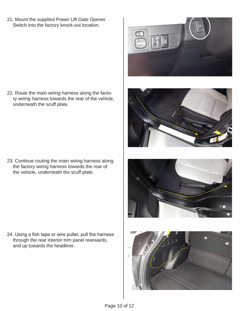
21. Mount the supplied Power Lift Gate Opener Switch into the factory knock-out location.
22. Route the main wiring harness along the facto-ry wiring harness towards the rear of the vehicle, underneath the scuff plate.
23. Continue routing the main wiring harness along the factory wiring harness towards the rear of the vehicle, underneath the scuff plate.
24. Using a fish tape or wire puller, pull the harness through the rear interior trim panel rearwards, and up towards the headliner.

Page 11 of 12
25. Carefully pull the main wiring harness through the harness boot and into the lift gate door.
NOTE: Spraying a bit of soap/water solution inside the wire harness boot will help to pull the harness through easier.
26. Route the main wiring harness along the fac-tory wiring harness towards the main control module. Route the other previously installed T-Harnesses to the main control module, following the factory wiring harness, securing with cable ties as necessary.
27. Install the supplied lift gate handle cup with the open/close switch and route the wire harness to the main control module. Make all connections to the main control module per the diagram on the module.
28. IMPORTANT: Prior to closing, ensure door panel is re-installed. Manually close the lift gate to initialize the Power Lift Gate System. Function test the system to verify proper operation.

Page 12 of 12
THESE POINTS MUST BE CHECKED TO ENSURE A QUALITY INSTALLATION
Head Light
High Beams
Turn Signal Lights
Tail Lights
Stop Lights
Backup Lights
Hazard Lights
Marker Lights
Dome/Courtesy Lights
Panel/Switch Illumination
Accessory Controls/Illumination (if equipped)
Rear Window Defogger (if equipped)Key Sensor Buzzer
Fog Lights (if equipped)
Day Time Running Lights (if equipped)Trunk/Tailgate/Bed Lights (if equipped)Glove Box Light (if equipped)
ABS Light (if equipped)
Rear Wiper/Washer (if equipped)
Clock (if equipped)
Accessory Power Socket (if equipped)Starter
Audio/Video (if equipped)
Power Sliding Door (if equipped)
If the warning lights remains on, it may indicate a system malfunction.
Convenience Memory Settings (if equipped)
Heated Seats (if equipped)
Massage Seats (if equipped)
Power Side Mirrors (if equipped)
Side Mirror Defogger (if equipped)
Front Windshield Defogger (if equipped)
Navigation System (if equipped)
Rear Sunshade (if equipped)
Cruise Control Light (if equipped)
Steering Wheel Audio Control (if equipped)HVAC
Power Locks (if equipped)
Power Windows (if equipped)
Gauges
Front Wiper/Washer
Hood Latch Release
Passenger Air Bag Switch (if equipped)
Rollover Side Curtain Air Bag Switch (RSCA)
Horn
Seat Belt Warning Light
Air Bag Warning Light
Lamp Failure Sensor
Track/Skid Control Light (if equipped)
If the warning lights remains on, it may indicate a system malfunction.
If the warning lights remains on, it may indicate a system malfunction.
If the warning lights remains on, it may indicate a system malfunction.
If the warning lights remains on, it may indicate a system malfunction.Tire Pressure Monitoring System (TPMS)Prior to TPMS activation and Pre-Delivery Service (PDS) of the vehicle the TPMS light will blink when IG is turned on. After TPMS activa-tion and PDS of the vehicle the TPMS light will illuminate for a few seconds and go off when IG is turned on.