international design project - university of idaho proj… · web viewinternational design...
TRANSCRIPT
International Design Project
Lego Snow Groomer
Final Report
École nationale d’aérotechnique – Saint-Hubert, Québec, CanadaUniversity of Idaho – Moscow, Idaho, USA
February 10th, 2010

Project Description
Global design, manufacturing, and assembly of engineering products have become more and more commonplace in the last decade. Part owners and assemblers are often thousands of miles and multiple time zones apart, yet they need to coordinate design changes and resolution of manufacturing problems as if they were under the same roof. In an effort to simulate global engineering in an introductory CATIA course, 15 students from University of Idaho in Moscow, Idaho and from École Nationale d'Aérotechnique in Montréal, Québec, organized themselves into four part owners/manufacturers and four sub-assembly managers/system integration houses with the mission of creating a 590 piece LEGO model of a snow cat/groomer. Part owners were responsible for making changes throughout the product lifecycle (i.e. until the main assembly and final documentation was complete). Sub-assembly managers were responsible for communicating errors in part design and resolving all issues in sub-assembly realization. Relational part design was implemented to the greatest extent possible using design tables/formula features. Part histories were linked with solid models by employing the part model comment feature. Public problem reporting, status updates, and reworked part storage via the campus.3ds.com website was used to track change orders and deliver reworked components. In addition to fully functional, rendered sub-assemblies, design teams generated detailed assembly instructions that were illustrated with interactive 3D models. This poster/presentation describes project management protocols devised by the student teams, summarizes lessons learned about concurrent engineering, and provides a framework for teaching initial stages of product lifecycle management in an introductory CATIA course. The Campus.3ds dedicated web page is found at: http://campus.3ds.com/students/project-showroom/go/project/ international-design-project-lego/
ENA Group Leader: Michel Michaud - [email protected]
Team 1 Team 2 Team 3
Mike René Maxime Leguerrier Kiril DimitrovMaxime Laberge Natacha Plante Samuel CouillardJacques Bergeron Roch-Antoine Lachaine Mathieu Bluteau
Alexandre Bonvouloir Hugo Duval Martin RichardSimon G. Lamarre William Henry-Dettwiler David Lavoie-Lacerte
University of Idaho Group Leader: Cam Stefanic - [email protected]
Team 1
Jennifer HasenoehrlChristopher Dyke
David Eld
2

École nationale d’aérotechnique Report
Software
Access to CATIA R19 was limited due to the fact all classes are using R18 at the moment. R19 was installed on a couple of workstations, but unfortunately not enough. In a future version of a similar project a minimum of 10 stations should be available with the right software from day 1.
Individual modeling
Deadline for submitting complete models were generally respected. Some discrepancies were found in models when assemblies were started to be built, that led to part modification and delays in assemblies.
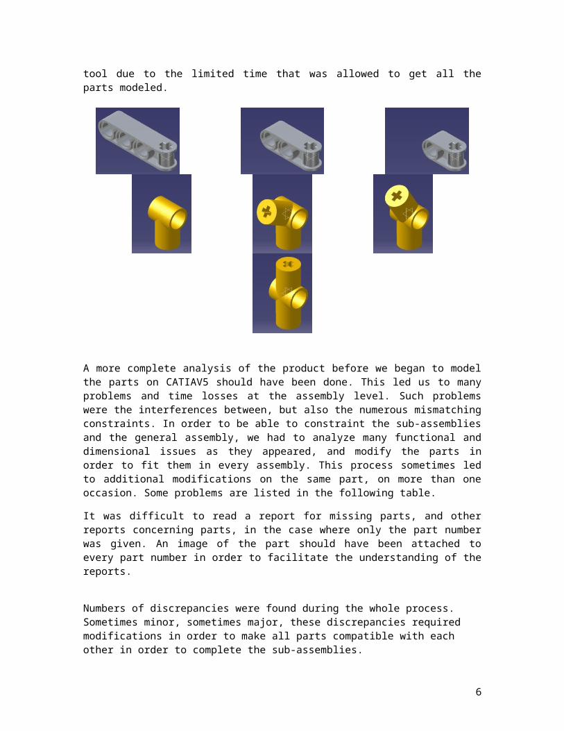
Parametric models, design tables, conditions and Powercopies were made to generate parts from the same family or similar geometry but they were more generated as an exercise than as a designing tool due to the limited time that was allowed to get all the parts modeled.
3

A more complete analysis of the product before we began to model the parts on CATIAV5 should have been done. This led us to many problems and time losses at the assembly level. Such problems were the interferences between, but also the numerous mismatching constraints. In order to be able to constraint the sub-assemblies and the general assembly, we had to analyze many functional and dimensional issues as they appeared, and modify the parts in order to fit them in every assembly. This process sometimes led to additional modifications on the same part, on more than one occasion. Some problems are listed in the following table.
It was difficult to read a report for missing parts, and other reports concerning parts, in the case where only the part number was given. An image of the part should have been attached to every part number in order to facilitate the understanding of the reports.
Numbers of discrepancies were found during the whole process. Sometimes minor, sometimes major, these discrepancies required modifications in order to make all parts compatible with each other in order to complete the sub-assemblies.
Here are some examples of problems that were found:
4

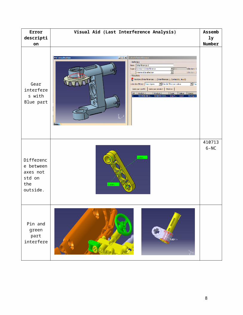
Error description
Visual Aid (Last Interference Analysis) Assembly Number
Gear interferes with Blue
part
Difference between axes not std on the outside.
4107136-NC
Pin and green part interfere
5
Assembly modeling – Team work
Exchange of information between team members working on parts and sub-assemblies that had to fit together was not optimal. Every member had to inform the person doing the following assembly about the problematic areas in his assembly and work out a solution with this person if he couldn’t do so individually because of lack of insight on the next assembly. The inverse process had to be done as soon as possible if parts were determined to be problematic.
Some problems occurred because of a lack of analysis of the sub-assemblies of our 3D product. Even if, in some cases, dimensions were correct, some of the sub-assemblies were constrained in a way which was not appropriate for the following assembly. The sub-assemblies should have been constrained with respect to the higher assemblies they were part of.
The general assembly is not properly oriented according to the coordinate system which will cause problems when using Photo Studio. A fixed part or sub-assembly in the product was required in order to ensure the right position of the product according to the coordinate system.
The chain doesn’t fit perfectly on the wheel frame. The chain and wheels should have been analyzed and calculations should have been done before modeling, in order to assure the accurate fitting of the chain.
Some of the changes made by the team members working on the late stages of the assembly affected the sub-assemblies done by other team members. Each member had to keep the latest working update of his parts and sub-assembly, in order to be able to use it if changes were made by mistake or by necessity. Using the original sub-assemblies at the final stage of the project was in this case inevitable in creating DMU fitting animations.
Some constraints that should have been done in higher assemblies were sometimes done in a lower assembly just to orient a part in space and were left there. The final position of these parts being defined only in the next assembly—these “dummy” constraints, more than once, caused problems in the final assembly. Every time such a problem was occurring, it was necessary to
Identify the constraint that was avoiding spatial displacement (which could take a non-negligible amount of time;
Erase it and make sure it would not affect anything else in the assembly; Create a new constraint in the final assembly.
Unfortunately, this kind of modification was done, too often, without advising the person that was responsible for the lower level assembly. This lack of communication, caused most of the time by short amount of time available, could sometimes create confusion between different team members.
Again, due to the format of the project (work done at different times by different people without daily meetings) these kinds of problems are difficult to avoid.
Here are the assemblies the ENA team were responsible for:
6

ENA Sub-Assemblies
7
Model History
A number of modeling standards have been set from the beginning. On some parts, these standards were unfortunately not followed, but problems were sometime more complex: the part analysis was not complete enough and some important but less evident standards were not taken into account. Since many parts are interdependent, it happened in some cases that axis were not coincident between adjacent parts or between another cross or pin. Again, a proper analysis of the different chains of dimensions would have been of great help. This would have saved us a lot of time.
A good example of this can be mentioned: Elbows 4254606, 4227544 and 4234429.
These elbows are used a lot and make contact with other parts determining then the location of axis.
The length of these elbows was not standardized from the beginning but had to become standard as the sub-assemblies were made. Many problems were related to offset location of axis making constraints impossible to be created.
Wrong Pin length and imprecise part thicknesses also generated a number of interferences.
It is also important to mention that some parts are assembled with a gap or a play in the physical model. This also makes the constraining of the virtual parts more difficult and lead to a number of assembly interferences.
Assembly History
All assemblies, from the first to the last, had to be reworked in order to update part changes or to change some assembly constraints in order to let the sub-assembly fit with its higher assembly.
Many sub-assemblies have been modified to become Flexible assemblies in order to facilitate this process.
Generally, Assembly problems found were:
Non-coincident axis (no standard defined); Interference problems due to non-standardized part sizes; Badly constrained assemblies; Overly constrained assemblies; Missing constraints in some assemblies (parts moving after an update).
At the last step, missing standards for some parts and sub-assemblies made the final assembly almost impossible to complete. It was decided to add some virtual parts (skeleton) in some assemblies in order to make sure that some critical dimensions were respected and were
8

standard. This helped us keep certain stability in the final assembly and minimize the effect of cumulated errors.
At this point, the final assembly was made. However, a major interference still existed between one of the Cab doors and a surrounding vertical support.
Animations
Making the animations demanded for a bit of time at the beginning in order to become familiar with DMU-Fitting module. However, after a few days, people started to spread the tricks learned to others in a way that, after about two weeks, most participants became comfortable with the software.
Reviewing the different animations raised some flags and helped to set up a number of standards in order to have a more consistent result in all animations.
These standards were:
Using a white background; Apply materials on parts and use Shading with Material when recording the animation; Try to get a similar displacement speed for parts in all animation.
The two first points are easy to achieve, but the last one ask for a bit of "video analysis”: Running the animation the first time allows to get a Total time and a Speed that depends of the different trajectories. Once the first animation is done, it is possible to rework it using a slower or a faster speed, in order to get a similar result from one animation to another.
It was not possible to complete all animations by the end of the fall semester. However, most students came back from their Christmas Holiday a few days earlier in order to complete all animations and to prepare a short video presenting them all together. This video was presented to staff members during the Winter Welcome Breakfast held by our director.
The video is available on Youtube.com at the following address:
http://www.youtube.com/watch?v=VSGAw2j9i-c
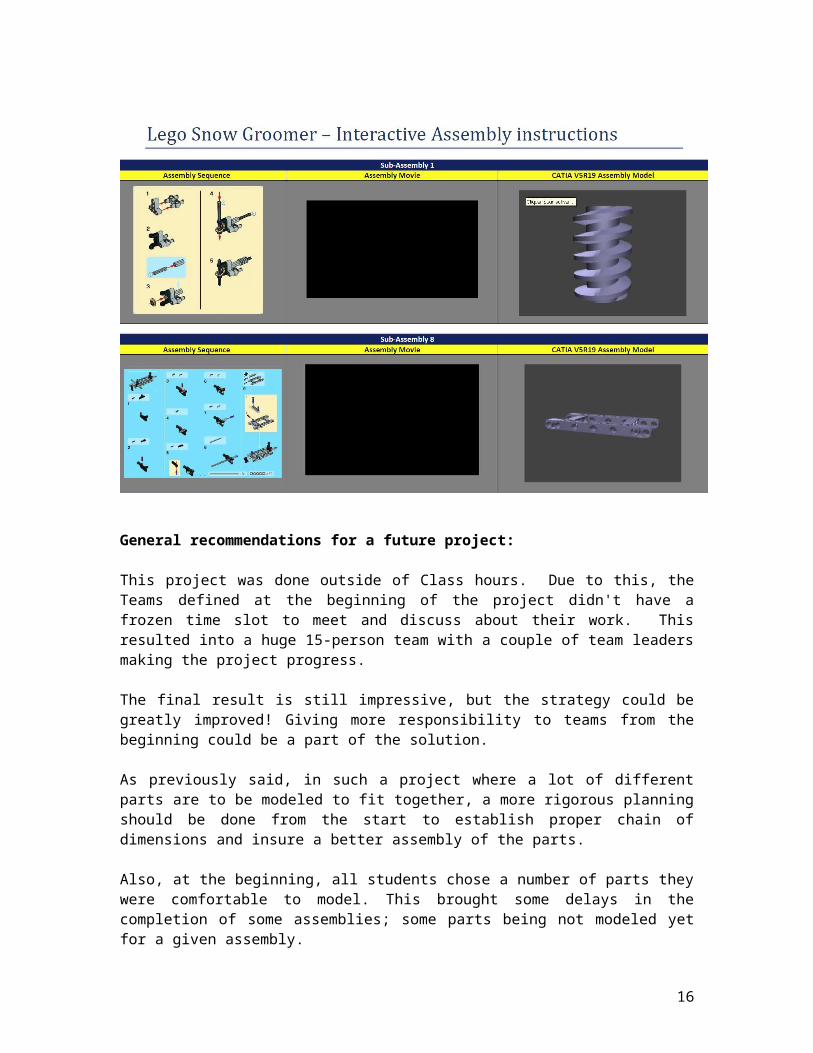
Visual Aid Document:
The creation of the document should reuse the Lego sequence provided with the toy and should incorporate Screen grabs done from the different assemblies and videos prepared with DMU-Fitting.
Some attempts were made using Acrobat 9 in order to incorporate animations, 3D dynamic assembly and assembly info in a .pdf document. The result was quite interesting, but the time necessary to make such a document was a problem.
9

General recommendations for a future project:
This project was done outside of Class hours. Due to this, the Teams defined at the beginning of the project didn't have a frozen time slot to meet and discuss about their work. This resulted into a huge 15-person team with a couple of team leaders making the project progress.
The final result is still impressive, but the strategy could be greatly improved! Giving more responsibility to teams from the beginning could be a part of the solution.
As previously said, in such a project where a lot of different parts are to be modeled to fit together, a more rigorous planning should be done from the start to establish proper chain of dimensions and insure a better assembly of the parts.
Also, at the beginning, all students chose a number of parts they were comfortable to model. This brought some delays in the completion of some assemblies; some parts being not modeled yet for a given assembly.
It has been proposed that parts should be assigned "by assemblies" instead of by choice. This would demand complete part identification at the beginning and then a list of priority in the part modeling sequence.
This is not a bad idea and it would be worth a trial in a future edition of a similar project.
10

As a final commentary from the "teaching side" of this story, it has to be mentioned that having a demanding project like this requesting 15 people to work together with another team located at the other end of the continent was very interesting.
Having people spending long hours between and after class, even on week-ends on a so demanding project without complaining about complexity or amount of work involved was a revelation!
Reverse Engineer a product like a Lego toy is not a simple thing. Many people realized by working on this project how well-made these parts were! A number of problems happened in this experience, but it was our first time... and we are not Reverse engineering specialists! Next time will be much better!
We really hope to be able to take part in a similar project next year, because this international project was quite interesting. It would then be fine to have more countries involved to increase the communication challenge. If it is not possible for some reason, we could try to develop our own Lego challenge within our walls or among different schools, but it definitely would not be so exciting!
11

University of Idaho report
Software:
The University of Idaho is running the latest educational version of CATIA (V5R19), which supports all parts created in past versions. However, the past versions cannot read V5R18/17/16(etc) parts that have subsequently been opened and edited by R19.
In this project we used CATIA V5R19 as the standard version. Through this project we were able bring all the skills we learned throughout the together to complete a product in CATIA. Working with a group external to our university has helped further our learning of the software being able to exchange knowledge of different aspects of the program such as design tables and power copies. We also got to learn about making sure to plan and keep track of software licensing, while not directly related to CAD modeling it is relevant to our future professional careers as engineers.
12
Individual modeling:LEGO parts have standard dimensions for holes, part lengths and widths, connectors, and rods among other pieces. For consistency, these common dimensions were posted and shared between the two groups.
Part # 4211050
It is a peg with different length couplings on either side. It would have been a good candidate for being made using a design table and the peg with equal length couplings on either side.
Part # 4211483
This part has a Technic style coupling on one side and a standard size Lego stud on the other. While similar to the other pegs it would not make a great candidate for a design table part because that side with the standard connector has significantly different geometry.
13

Part # 4210751
This piece is a standard 3-hole bar. It would have been a good candidate for being a design table part based off of the 2-hole bar as the base piece. Although having it a unique part was handy for making part 4538007.
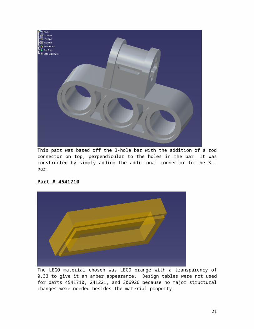
Part # 4538007
This part was based off the 3-hole bar with the addition of a rod connector on top, perpendicular to the holes in the bar. It was constructed by simply adding the additional connector to the 3 – bar.
14

Part # 4541710
The LEGO material chosen was LEGO orange with a transparency of 0.33 to give it an amber appearance. Design tables were not used for parts 4541710, 241221, and 306926 because no major structural changes were needed besides the material property.
Part # 241221
This part was made using part 4541710. First, LEGO red was applied as the material, then grooves were cut into the side surface along its length, and last, a knob was added to the inner surface.
15
Part # 306926
This part was made by using part 4541710 and applying LEGO black as the material.
Part # 4563044
This part was created using similar parts. Power copies would have been helpful in the creation of this part with the grooves and holes.
16

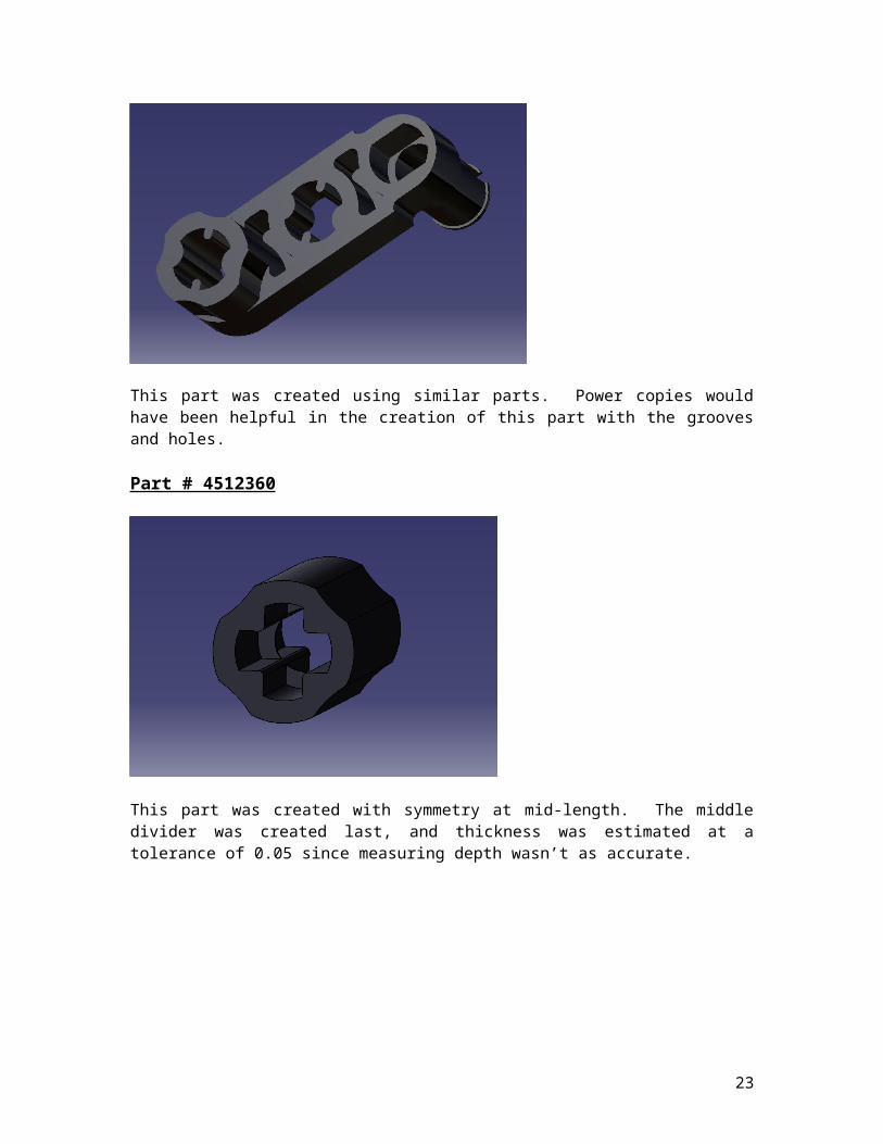
Part # 4512360
This part was created with symmetry at mid-length. The middle divider was created last, and thickness was estimated at a tolerance of 0.05 since measuring depth wasn’t as accurate.
17

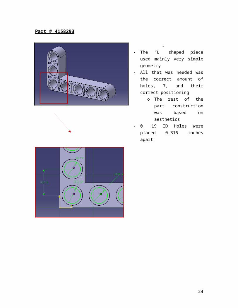
Part # 4158293
- The “L” shaped piece used mainly very simple geometry
- All that was needed was the correct amount of holes, 7, and their correct positioning
o The rest of the part construction was based on aesthetics
- 0. 19 ID Holes were placed 0.315 inches apart
18

Part # 4114634
- Part #4114634 also required very simple geometry- Hole placement and size remained the same- The width and thickness of all parts were 0.298 and 0.155 inches, respectively
19

Part # 4211553
- Both intrusions had the same geometry, but had different surrounding dimensionso Width of .077, OD of .095 and inner radii of .01 inches
- Other geometries such as top holes, square and cylindrical pocket, and edge fillets were all for aesthetics
20
Assembly modeling – Team work:
Sub-Assembly 2
Step 1: blue connectors into red shield piece.
Step 2 and 3: black connectors into red connectors, then red connectors and rods collapse onto the blue connector.
21

Sub-Assembly 3
This assembly is the seat that goes inside the cab of the snow groomer. It is a fairly simple assembly with 7 parts, using concentric and coincident constraints.Sub-assemblies: pics, special features, etc.
22
Sub-Assembly 4
This assembly is the steering assembly for inside the cab of the snow groomer. It consists of 6 parts and was a simple assembly to construct using coincident and concentric constraints.
23
Sub-Assembly 9
- Started out with the chassiso Was the same linear
design; mirrored over the center axis
- the end fittings were attached- Concentric and face mates were the
most used
24
Step 1
Step 2
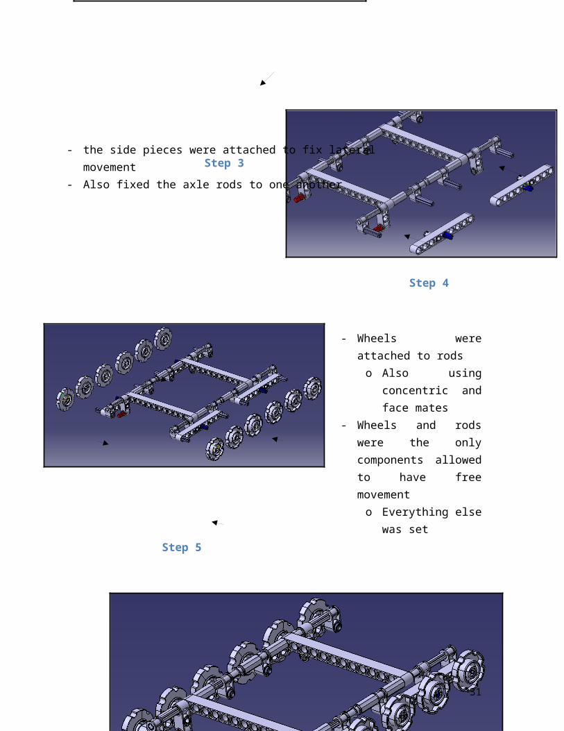
Step 3

- the side pieces were attached to fix lateralmovement
- Also fixed the axle rods to one another
- Wheels were attached to rodso Also using concentric
and face mates- Wheels and rods were the
only components allowed to have free movemento Everything else was
set
25
Step 4
Step 5
Final Sub-Assembly

Sub-Assembly 9 Tree
26

Model History:
Once the parts were modeled, the assemblers were to let the part owner know what needed fixed. Notes were to be kept in the “properties” box of the part as well as a name change noted in the previous model history section.
Assembly History:
The assemblies were created using the initial parts. As conflicts in part mates were found, the parts were then referred back to the original owner. Some of the discrepancies were due to the tolerances of initial measurements. Since the LEGO parts were small to begin with and then placed together in the assembly, tolerance issues compounded.
Dynamic Assembly:
The making of dynamic assemblies of sub-products taught us several lessons. One lesson, was that the majority of parts in LEGO products, particularly the Snow Cat Groomer, are static; meaning they move relatively with each other. The only parts in the entire assembly that move are the adjustable rods that control upward and sideward movement. So out of 590 pieces only 25 or so are kinetic components.
For the dynamic assembly, we here at the University of Idaho dealt with the tracks. Upon completion of the 9th sub-assembly, we quickly realized most constraints made were useless. Because most parts on the assembly are stationary, they can be treated as static components. The wheels and the holding rods are the only dynamic parts. Constraints were made to keep them concentric with the chassis and limit lateral motion. By limiting sideways movement, the wheel would stay fixed with the static assembly. Once constraints are applied, kinematic motion can be implemented.
It wasn’t long before we realized the tracks are a very difficult dynamic to simulate. Because the tracks are always moving they are never constrained to one specific wheel, but many. The tracks follow an elliptical shift which gives the possibility of putting the track on a set path. The path would then be related to a specific rotational speed of the wheels; this is done by driving one wheel and moving the assembly in a forward lateral motion. This is where the knowledge of the Idaho team ran quite thin. Another problem with dynamically moving the tracks was caused by the “looseness” of the tracks. In reality the tracks have a bit of “hang” or separation between the wheels due to gravity. If the tracks were completely stiff they wouldn’t move at all. This was a solution Team Idaho once again didn’t have time to work out.
27

Visual Aid Document:
Assembly 2
Assembly 3
28

Assembly 4
Assembly 9
29

30
Final Assembly
General recommendations for a future project:
There are several recommendations that Team Idaho will present:
1.) Use a common repositorya. Easier accessb. Easier transfer of documentsc. Eliminates file saving problems due to different save locationsd. Possibly online locatione. Immediate posting of parts
i. Gets rid of individual emailii. Saves time
2.) Focus on rendering final productsa. Rigid body complications make it harder to dynamically simulate
3.) Set guidelines earlya. Identifies problems quickerb. Make sure they are followed
4.) Hold Inter-Team Meeting’s earlier in the weeka. Increases motivation of members by starting out fresh
5.) Hold Skype meetings with videoa. Difficult to relay ideas and points of such a visual project
Conclusion:
This project offered lots of learning experience in the classroom that would otherwise only be available in an industrial setting. By forcing students to transcend language and culture barriers as well as retain personal ownership of .CATParts, there is a very real-world facet to the project.
31