interface control document bte super...
TRANSCRIPT

University of North Dakota
University of North Dakota
INTERFACE CONTROL DOCUMENT
BTE SUPER HAULER
http://www.uase.und.edu
School of Engineering and Mines Center for UAS Research Upson II Room 165 John D. Odegard School of Aerospace Sciences 243 Centennial Drive, Stop 8155 3980 Campus Road, Stop 9007 University of North Dakota University of North Dakota Grand Forks, ND 58202 Grand Forks, ND 58202 Dr. William Semke Dr. Richard Schultz [email protected] [email protected] 701-777-4571 701-777-4429

BTE SUPER HAULER INTERFACE CONTROL DOCUMENT
REVISION HISTORY Version
# Implemented
By Revision
Date Reason
1.0 Wyatt Shallbetter
12/10/09 Draft Finalization
2.0
Wyatt Shallbetter
1/14/10 Draft Update and Edit
Page 2 of 28 University of North Dakota

BTE SUPER HAULER INTERFACE CONTROL DOCUMENT
TABLE OF CONTENTS
REVISION HISTORY .................................................................................................................2
TABLE OF CONTENTS .............................................................................................................3
1.0 INTRODUCTION....................................................................................................................4 1.1 Purpose......................................................................................................................................4 1.2 Scope..........................................................................................................................................4 1.3 Reference Documents....................................................................................................... .......4 1.4 List of Acronyms and Abbreviations.............................................................................. .......4 2.0 AIRCRAFT OVERVIEW............................................................................................... ........5 2.1 Engine Information ..................................................................................................................5 2.2 Aircraft Dimensions .................................................................................................................5 2.3 Airframe Details .......................................................................................................................6 2.4 Airframe Control Systems ......................................................................................................8 2.5 Aircraft Electrical Information ............................................................................................10 3.0 PAYLOAD DESCRIPTION .................................................................................................13 3.1 Payload Environment ............................................................................................................14 3.2 Physical and Mechanical Interface.......................................................................................14 3.3 Payload Weight and Balance Information ..........................................................................16 3.4 Payload Electrical Interface Information ............................................................................16 4.0 PICCOLO II AUTOPILOT ..................................................................................................16 4.1 Piccolo II Integration .............................................................................................................17 4.2 Piccolo II Wiring Assignments .............................................................................................19 5.0 AIRCRAFT COMMUNICATIONS ....................................................................................21 5.1 UHF Communication.............................................................................................................21 5.2 UAT Communication.............................................................................................................23 5.3 Video Communication ...........................................................................................................23 6.0 POWER DISTRIBUTION ....................................................................................................24 6.1 Autopilot Power Distribution ...............................................................................................24 6.2 Ignition Power Distribution ..................................................................................................25 6.3 Servo Power Distribution ......................................................................................................27 6.4 Video Power Distribution ......................................................................................................28 7.0 SUMMARY ............................................................................................................................28
Page 3 of 28 University of North Dakota

BTE SUPER HAULER INTERFACE CONTROL DOCUMENT
1.0 INTRODUCTION The Unmanned Aircraft Systems Engineering (UASE) laboratory in the SEM at the University of North Dakota (UND) operates in conjunction with the John D. Odegard School of Aerospace Sciences, and the Northern Plains Center for Behavioral Research. As a center of excellence for unmanned aircraft systems research and education, students and faculty at the University of North Dakota work to promote the commercialization of new UAS-related products. 1.1 Purpose The purpose of this guide is to provide a detailed background of the mechanical and electrical interface requirements of the BTE Super Hauler UAV operated by the UASE research group at the University of North Dakota. 1.2 Scope This document applies to all current and potential users of the BTE Super Hauler. The electrical and mechanical interface requirements of the BTE Super Hauler payload module will be covered as well as basic aircraft information. 1.3 Reference Documents BTE Super Hauler Pilot’s Operating Handbook Payload Integration Manual for BTE Super Hauler BTE Super Hauler Maintenance Manual 1.4 List of Acronyms and Abbreviations ICD Interface Control Document POH Pilot’s Operating Handbook UAS Unmanned Aircraft Systems UASE Unmanned Aircraft Systems Engineering BTE Bruce Tharpe Engineering SEM School of Engineering and Mines UND University of North Dakota UAV Unmanned Aerial Vehicle EMI Electromagnetic Interference RPM Revolutions Per Minute PGS Portable Ground Station
Page 4 of 28 University of North Dakota

BTE SUPER HAULER INTERFACE CONTROL DOCUMENT
2.0 AIRCRAFT OVERVIEW This section will detail general aircraft specifications pertinent to correct and safe methods of operation for the BTE Super Hauler (Fig. 1). This aircraft was created for the University of North Dakota by Bruce Tharpe Engineering.
Figure 1: BTE Super Hauler.
2.1 Engine Information The BTE Super Hauler utilizes an engine manufactured by Desert Aircraft, the DA 100. The engine is rated at 9.8 horsepower and 8500 rpm. A two blade propeller with a diameter of 27 inches is fixed to the engine shaft. The suggested fuel for use in the BTE Super Hauler is a mid to high octane mixed with oil. 2.2 Aircraft Dimensions Basic airframe information is as follows:
• Wingspan: 144 in. • Wing Area: 3680 sq. in. • Length: 120 in. • Standard Empty Weight: 48 lbs. • Maximum Takeoff Weight: 90.21 lbs.
Page 5 of 28 University of North Dakota

BTE SUPER HAULER INTERFACE CONTROL DOCUMENT
BTE SUPER HAULER DESIGNED AND MANUFACTURED BY: BRUCE THARPE ENGINEERING 8622 E EVANS CREEK ROAD ROGUE RIVER, OR 97537 541-582-1708
Figure 2: Airframe dimensions of BTE Super Hauler. 2.3 Airframe Details The BTE Super Hauler’s wing section consists of a 6 foot long center section and two outer sections measuring 3 feet each. The two outer panels, each spanning three feet, are removable for easy transport. In this airframe, a pitot tube is incorporated in the wing joint on the left-hand side (Fig. 3). Construction is traditional model airplane - balsa ribs and sheeting; hardwood main spars (Fig. 3). Fuselage sections are bolted together and may be disassembled for transport, if necessary (Figs. 4 and 5). The rear fuselage section features a large hatch for access to the radio equipment and autopilot. Removable plywood plates make this area easy to re-configure or modify. Servo wires for aileron control are routed up and over the wing trailing edge, so connections can be made quickly and easily after assembly. The covering is all Monokote, chosen for its light weight and easy reparability. The tail unit is comprised of the fin, rudder, stabilizer, and elevator. It is removable with five bolts for transportation ease. Adjustable tail brace wires are used for tail strength and rigidity (Fig. 6). The wing joiners were manufactured by Sig Mfg. in Iowa. These are critical to the integrity of the wing structure and should be inspected carefully (for looseness, cracking, bending, or any other abnormality) whenever the wing panels are joined. The joiners are held together with set screws (4-40 x 3/8” socket head bolts), accessed through holes in the bottom of the center wing panel. It is recommended to use a
Page 6 of 28 University of North Dakota

BTE SUPER HAULER INTERFACE CONTROL DOCUMENT
3/32” ball driver to tighten these screws by hand, and nothing more, to avoid over tightening and possible stripping of the threads.
Figure 3: Uncovered wing section showing rib construction and wire encasements.
Figure 4: Fuselage front section. Figure 5: Fuselage rear section.
Page 7 of 28 University of North Dakota

BTE SUPER HAULER INTERFACE CONTROL DOCUMENT
2.4 Airframe Control Systems Wires Tail brace wires (figure #6) are Berkley brand nylon coated wire, 25 lb. test, .028” diameter. All wires are adjustable using the clevis at one end. These do not have to be tight, but there should be no slack when adjusted properly. When adjusting, avoid twisting or bending the horizontal stabilizer. Rudder cables are also Berkley brand nylon coated wire, 25 lb. test, .028” diameter, and. Again, these do not need to be tight, but should have a definite tension. Control wires use threaded couplers for connections to control surfaces and the servos controlling the aircraft. Crimps are used to control the length of the wire and are covered in a heat shrink wrap.
Figure 6: Tail brace wires for tail stability and rigidity.
Brace wires
Figure 7: Left: control wire connected to a servo horn. Center: control wire connected to a control surface with the shrink wrap clearly visible. Right: Installation of the wire through a
coupler and crimped to the desired length.
Page 8 of 28 University of North Dakota

BTE SUPER HAULER INTERFACE CONTROL DOCUMENT
Control Horns and Clevises Sullivan S567 Super Horns are used for the ailerons, flaps, and elevators. A Sullivan S568 Double Super Horn is used for the rudder (Fig 8). Sullivan S526 Gold-N-Clevises with 4-40 thread are used throughout (Fig. 8). Sullivan clevises use a tiny, silver locking clip on the clevis pin to keep it from opening. These clips should always be used, but they are particularly critical for the control surfaces.
Figure 8: Left: Sullivan S568 Double Super Horn used for the rudder control. Also seen in
picture is copper shielding around and wire shielding to prevent EMI interference. Right: Servo used for aileron control with a single horn as well as the Sullivan S526 Gold-N-Clevises with 4-
40 thread for connecting control wires.
SERVO
Pushrods There are three types of pushrod styles used on this airplane. The ailerons, flaps, and elevators use a carbon fiber pushrod (Fig. 9), the throttle uses a flexible pushrod (Fig. 10), and the nose wheel steering system uses a wood and steel wire reinforced pushrod. Carbon fiber pushrods are used on the aircrafts primary flight controls for their light weight and because it is not necessary the pushrods for these applications to be extremely strong. The nose wheel steering pushrod is constructed of heavier duty materials to handle the heavier load associated with steering the aircraft while on the ground and withstand impacts or sudden jolts.
Figure 9: Carbon fiber pushrod used for ailerons, flaps, and elevators. Also shown are basic
components of the pushrod.
Page 9 of 28 University of North Dakota
BTE SUPER HAULER INTERFACE CONTROL DOCUMENT
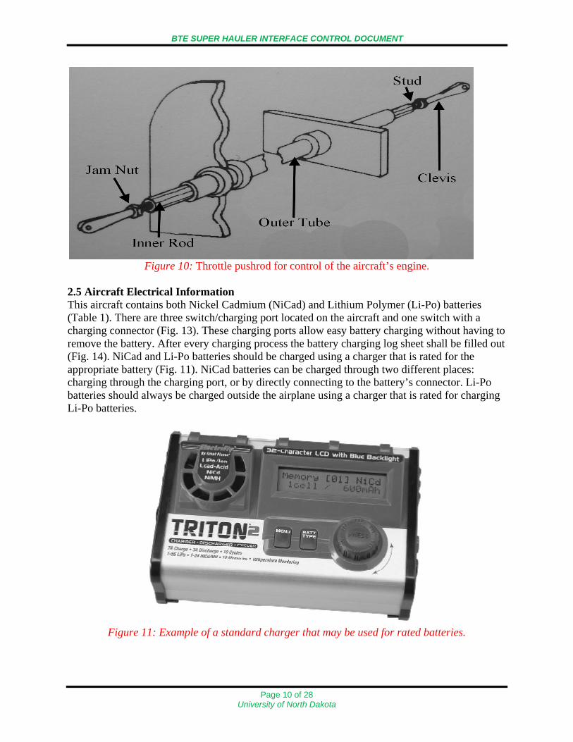
Figure 10: Throttle pushrod for control of the aircraft’s engine.
2.5 Aircraft Electrical Information This aircraft contains both Nickel Cadmium (NiCad) and Lithium Polymer (Li-Po) batteries (Table 1). There are three switch/charging port located on the aircraft and one switch with a charging connector (Fig. 13). These charging ports allow easy battery charging without having to remove the battery. After every charging process the battery charging log sheet shall be filled out (Fig. 14). NiCad and Li-Po batteries should be charged using a charger that is rated for the appropriate battery (Fig. 11). NiCad batteries can be charged through two different places: charging through the charging port, or by directly connecting to the battery’s connector. Li-Po batteries should always be charged outside the airplane using a charger that is rated for charging Li-Po batteries.
Figure 11: Example of a standard charger that may be used for rated batteries.
Page 10 of 28 University of North Dakota

BTE SUPER HAULER INTERFACE CONTROL DOCUMENT
BATTERY DATA AND LOCATIONS
NAME TYPE LOCATION CONNECTS TO SWITCH CONNECTION
UND 01 6V, 2400mAh NiCad In Airplane Ignition System Ignition Switch UND 02 UND 03
6V, 2400mAh NiCad In Airplane Servo Power Input Servo (S) Switch
UND 08 UND 09 UND 10
14.8V, 4000mAh Li-Po
In Airplane Autopilot N/A
UND 06 UND 07
11.1 V 1500mAh Li-Po
In Airplane Video System Video Switch
Table 1: List of batteries located in the aircraft and their functions.
Figure 12: Diagram showing the approximate locations of aircraft batteries.
NAME STANDARD
CHARGER (yes/no)
CHANGING PORT
CHARGING (yes/no)
DIRECT CONNECTION
CHARGING (yes/no)
CHARGE AT (Amps)
UND 01 Yes Yes Yes 0.3 to 2.4 A UND 02 UND 03
Yes Yes Yes 0.3 to 2.4 A
UND 08 UND 09 UND 10
Yes No Yes
UND 06 UND 07
Yes No Yes
Table 2: Battery charging information.
Figure 13: Battery charging port and on/off switch.
Page 11 of 28 University of North Dakota

BTE SUPER HAULER INTERFACE CONTROL DOCUMENT
Figure 14: Example battery log.
Page 12 of 28 University of North Dakota

BTE SUPER HAULER INTERFACE CONTROL DOCUMENT
3.0 PAYLOAD DESCRIPTION BTE Super Hauler payloads are carried within a cubic payload bay with approximately 3064 cu. in. of space. The entry width of the payload is 11.5 in. at the front and 10 in. at the rear. The overall entry length of the payload bay is 21.75 in. Payloads should not exceed a total weight of 30 pounds. There are two openings at the bottom of the payload bay on the underside of the aircraft (Fig. 15). The payload bay is also lined with copper shielding to help protect against EMI interference that may adversely affect the aircraft’s telemetry (Fig. 16). An EMI resistant gasket is also placed around through connections to help fully shield the payload bay from the aircraft’s electronics (Fig. 16).
Figure 15: View from above of the payload bay showing the two openings. The larger opening
on the left side is towards the front of the aircraft.
Figure 16: Left: Copper shielding lining the payload bay. Right: EMI gasket and wire shielding
to protect payloads and aircraft electronics.
EMI Gasket
Copper Shielding
Page 13 of 28 University of North Dakota

BTE SUPER HAULER INTERFACE CONTROL DOCUMENT
3.1 Payload Environment Payloads present on the BTE Super Hauler are not currently required to handle extreme weather conditions. The aircraft is currently used only in daytime VFR operations and almost never operated under icing conditions. Thus current basic requirements for payloads operated on the aircraft include: operational between temperatures ranging from 35°F to 120°F, resistant to some water exposure (high humidity, condensation, mist, light precipitation) encountered during normal operations, resistant and/or tolerant of dust, dirt and debris, additionally methods to clean the payload of dust, dirt and debris should be easily accomplished in the field, as well as able to withstand vibrations and shocks encountered while within the aircraft. 3.2 Physical and Mechanical Interface The payload bay has two quarter-turn mounting rails to attach payloads. This requires that payloads have a frame compatible with this mounting system in order to be securely fastened to the aircraft. The quarter turn fasteners that must be used to attach the payload frame are DFCI P/N 3506-SCxxxA-C3C or equivalent (Fig. 18). These fasteners allow the frame to be mounted into the receptacles DFCI P/N 3590-H320 installed in the BTE Super Hauler’s payload bay (Fig. 19).
Figure 17: Three dimensional view of the payload bay and fasteners.
Page 14 of 28 University of North Dakota

BTE SUPER HAULER INTERFACE CONTROL DOCUMENT
Figure 18: DFCI P/N 3506-SCxxxA-C3C quarter turn fasteners for attaching the payload frame.
Figure 19: DFCI P/N 3590-H320 receptacles mounted to the payload bay.
Page 15 of 28 University of North Dakota

BTE SUPER HAULER INTERFACE CONTROL DOCUMENT
3.3 Payload Weight and Balance Information Maximum allowable payload weight is 30 pounds. Overall Center of gravity can be calculated with the following method:
weightTotalmomentTotal
CG = Arm
WeightMoment =
Weight point Weight
(lbs) 90.21 max
Arm (inches)
Moment (in-lbs)
C.G. +30.0 to +38.5
Main Gear
48.5 37.5 1818.75
Nose Gear
5.5 7.0 38.5
Payload
37.75
Fuel (.04851 lb/ounce)
23
Total
Table 3: Weight and balance chart for BTE Super Hauler.
3.4 Payload Electrical Interface Information Payloads must be controlled by a separate ground station designated to the payload. Payload ground stations are responsible for controlling the individual functions of the payload. Payloads must provide their own up/down communication links. Payload power is not supplied by the aircraft. It is important that power sources be integrated into the payload in a manner that does not interfere with payload mounting or weight restrictions. Adequate power must also be supplied for the entire duration of testing. Payload electronics shall be grounded internally. The BTE Super Hauler does not provide any grounding locations. 4.0 PICCOLO II AUTOPILOT The autopilot used in this aircraft is a Piccolo II, made by Cloud Cap Technology (Fig. 20). The front panel of the Piccolo II autopilot includes the primary vehicle interface connector, GPS and UHF antenna connectors, Pitot and Static pressure port nipples (Fig. 20). The UHF and GPS antenna connectors are SMA coaxial cable connectors. The pitot and static ports provide the interface to the airplanes pitot/static system. The pitot and static pressure port nipples accept 3/32 ID tubing. The external interface connector is the main interface connector. It provides servo power control interface, general purpose I/O, and payload and programming serial ports. The Micro-D (MicroDot) external interface connector provides additional I/O, serial ports, and analog inputs.
Page 16 of 28 University of North Dakota

BTE SUPER HAULER INTERFACE CONTROL DOCUMENT
Figure 20: Left: Piccolo II ground station and necessary antennas. Right: Piccolo II autopilot
front face with all connection ports labeled. 4.1 Piccolo II Integration The autopilot is installed vertically on a soft foam mount and is orientated so the front panel of the autopilot faces the rear of the airplane (Fig. 21). As with the other wiring in the aircraft, all wiring associated with the Piccolo is shielded to prevent electromagnetic interference.
Figure 21: Piccolo II autopilot installed in the BTE Super Hauler.
Page 17 of 28 University of North Dakota

BTE SUPER HAULER INTERFACE CONTROL DOCUMENT
A portable ground station (PGS) is used to communicate with the autopilot through UHF antennas (Fig. 22). The PGS connects to a computer to be used as the Piccolo Command Center. General connection assignments for ports on the PGS are as follows: • Payload Serial Connector – Provides a RS232 or RS422 configured payload port on the
Piccolo. • Link 1 Serial Connector – The primary link interface and it is used to connect the PGS to the
PC running the Piccolo Command Center. It is a DB9 serial connector. • Link 2/Config Serial Connector – Used as a serial interface to a PC running as a second
Piccolo Command Center. It is a DB9 serial connector. • Link 1 and Link Antenna Inputs – Provides connections for the RF antennas. • Aux Supply Input – Allows you to run the system off an external 12 Volt battery. • Program Button – Used to put the PGS into program mode for updating the ground station
software. • Pilot Console Cable Connector – Used to connect the Futaba Pilot Console or Futaba T9CAP
Super Transmitter/Controller to the PGS. For more information on the Transmitter/Controller refer to 23-21-01, Transmitter/Controller – Description and Operation.
Figure 22: Portable ground station (PGS) used to communicate with the BTE Super Hauler with
all connection port assignments detailed.
Page 18 of 28 University of North Dakota

BTE SUPER HAULER INTERFACE CONTROL DOCUMENT
4.2 Piccolo II Wiring Assignments The wiring harness is used to connect the servos, servo input power, piccolo input power, tach/deadman board, and more to the external interface connector (Fig. 23). Detailed assignments for each connector can be seen in detailed wiring schematics provided on the following page (Fig. 24).
Figure 23: Wiring harness that connects to the external interface connector on the Piccolo II
autopilot. This is the wiring interface for communication between the autopilot and the aircraft control mechanisms.
Page 19 of 28 University of North Dakota

BTE SUPER HAULER INTERFACE CONTROL DOCUMENT
Page 20 of 28 University of North Dakota

BTE SUPER HAULER INTERFACE CONTROL DOCUMENT
5.0 AIRCRAFT COMMUNICATIONS This section will describe details on the communication methods for controlling the aircraft, communication with payloads, and video transmission methods. 5.1 UHF Communication The 900 MHz UHF COMM antenna operates in the 902-928 MHz ISM unlicensed band (Fig. 25). The 900 MHz antenna is a ¼ wave dipole antenna and it does require a ground plane. The antenna connects to a BNC Bulkhead connector that is connected to a SMA male connector, using 50 ohm coax cable. The SMA male connector connects to UHF connector on the Piccolo II autopilot. The antenna is located on the rear fuselage section, near the vertical stabilizer (Fig. 25 bottom).
Figure 25: UHF antenna and its location on the aircraft.
Page 21 of 28 University of North Dakota

BTE SUPER HAULER INTERFACE CONTROL DOCUMENT
The Futaba T9CAP Super Transmitter/Controller is used to manually control the airplane (Fig. 26). The transmitter/controller connects to the Portable Ground Station (PGS) through the pilot console cable connector on the PGS. The signal from the transmitter/controller is then transmitted through the PGS UHF antenna to the 900 MHz UHF antenna located on the airplane. The Transmitter/Controller is powered by the PGS.
Fig. 26: The Futaba T9Cap Super Transmitter/Controller and the functions controlled by each
part of the transmitter/controller are displayed above.
Page 22 of 28 University of North Dakota

BTE SUPER HAULER INTERFACE CONTROL DOCUMENT
5.2 UAT Communication Universal Access Transceiver (UAT) blade antennas are used from payload data transmission. This airplane contains two UAT antennas that are located on the center wing section (Fig. 27). The antenna located on the right side of the center wing section is pointed downwards and the antenna located on the left side is pointed upwards (Fig. 27). Each antenna is connected to a pass through connector located on the rear EMI Wall, to allow for the payload to be connected to the antennas.
Fig. 27: Left: The approximate location of each UAT antenna is displayed on the aircraft diagram. Right: The left side antenna is displayed pointing upwards.
5.3 Video Communication The video transmission system contains a forward looking camera, a transmitter, and a blade antenna (Fig. 28). The blade antenna has impedance of 50 ohms and has a SMA connector on it. The antenna is located on the lower access panel.
Figure 28: The location of the blade antenna used for video communication and access panels.
Page 23 of 28 University of North Dakota

BTE SUPER HAULER INTERFACE CONTROL DOCUMENT
6.0 POWER DISTRIBUTION There are four main power distribution systems; autopilot, ignition, servo, and video systems. The electrical power system contains only four switches that are located on the exterior of the aircraft. The ignition, receiver, and servo switches are DSC Super Switches. The ignition, receiver, and servo switches contain a charging port for easy battery charging without having to disconnect the batteries from the other components. The video switch contains a charging connector, which allows you to charge the battery without removing the battery from the airplane. The four switches are used to disconnect power from the four main power distribution circuits on this aircraft. The four switches are labeled as such: (1) Ignition Switch – Connects the ignition battery to the ignition system. (2) Receiver (Rx) Switch – Connects the receiver/autopilot battery to the autopilot system. (3) Servo (S) Switch – Connects servo battery to the autopilot and servo system. (4) Video Switch – Connects the video battery to the video system. 6.1 Autopilot Power Distribution The autopilot is powered by a 14.8 Volt, 4000mAh Lithium Polymer battery (Fig. 29).
Figure 29: Diagram detailing the Piccolo II autopilot power distribution.
Page 24 of 28 University of North Dakota

BTE SUPER HAULER INTERFACE CONTROL DOCUMENT
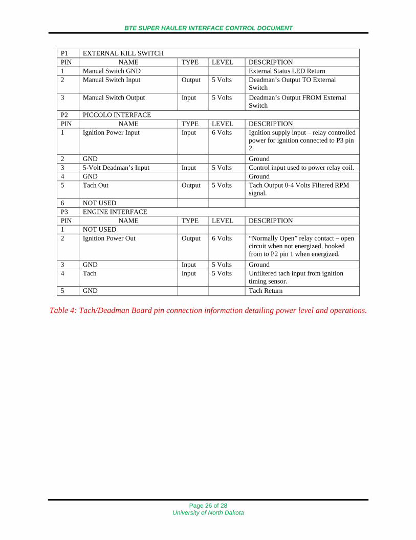
6.2 Ignition Power Distribution The ignition system is powered by a 6 Volt, 2400mAh Nickel-Cadmium battery and by the servo’s power distribution system (Fig. 30), which powers the Tach/Deadman board (Table 4).
Figure 30: Ignition power distribution diagram with Deadman/Tach Board also shown.
Page 25 of 28 University of North Dakota
BTE SUPER HAULER INTERFACE CONTROL DOCUMENT
P1 EXTERNAL KILL SWITCH PIN NAME TYPE LEVEL DESCRIPTION 1 Manual Switch GND External Status LED Return 2 Manual Switch Input Output 5 Volts Deadman’s Output TO External
Switch 3 Manual Switch Output Input 5 Volts Deadman’s Output FROM External
Switch P2 PICCOLO INTERFACE PIN NAME TYPE LEVEL DESCRIPTION 1 Ignition Power Input Input 6 Volts Ignition supply input – relay controlled
power for ignition connected to P3 pin 2.
2 GND Ground 3 5-Volt Deadman’s Input Input 5 Volts Control input used to power relay coil. 4 GND Ground 5 Tach Out Output 5 Volts Tach Output 0-4 Volts Filtered RPM
signal. 6 NOT USED P3 ENGINE INTERFACE PIN NAME TYPE LEVEL DESCRIPTION 1 NOT USED 2 Ignition Power Out Output 6 Volts “Normally Open” relay contact – open
circuit when not energized, hooked from to P2 pin 1 when energized.
3 GND Input 5 Volts Ground 4 Tach Input 5 Volts Unfiltered tach input from ignition
timing sensor. 5 GND Tach Return
Table 4: Tach/Deadman Board pin connection information detailing power level and operations.
Page 26 of 28 University of North Dakota

BTE SUPER HAULER INTERFACE CONTROL DOCUMENT
6.3 Servo Power Distribution The servo system is powered by a 6 Volt, 2400mAh Nickel-Cadmium battery. The servo battery is used to power servos and the Tach/Deadman Board. The servo battery does not power the ignition module (Fig. 31).
Figure 31: Servo power distribution diagram.
Page 27 of 28 University of North Dakota

BTE SUPER HAULER INTERFACE CONTROL DOCUMENT
6.4 Video Power Distribution The video system is powered by an 11.1 Volt, 1500mAh Lithium Polymer battery (Fig. 32).
Figure 32: Video Power distribution diagram.
7.0 Summary The goal of the Unmanned Aircraft Systems Engineering laboratory is to research and develop new technologies for use in the private and public sectors. Utilizing the BTE Super Hauler, students and faculty are able to test research projects in real world settings. Working with the John D. Odegard School of Aerospace Sciences, and the Northern Plains Center for Behavioral Research the UASE laboratory is continuously working to introduce new technologies into the marketplace. For additional information please contact either: Dr. William Semke Dr. Richard Schultz [email protected] [email protected] 701-777-4571 701-777-4429
Page 28 of 28 University of North Dakota