integrity, safety and efficiency in lng … integrity, safety and efficiency in lng transfer —...
TRANSCRIPT

1
INTEGRITY, SAFETY AND EFFICIENCY IN LNG TRANSFER — IMPACT OF EMERGENCY SHUTDOWN AND RELEASE OPERATIONS
Evert van Bokhorst Frank Driessen
Erik Nennie David Remans Jan Smeulers
TNO Technical Sciences Delft, the Netherlands ([email protected])
KEYWORDS: LNG transfer; emergency shutdown; emergency release operation; pressure surge; water hammer; column separation; wave propagation; damping; speed of sound
ABSTRACT
Caused by the global increase of demand for natural gas the interest in offshore liquefaction, transport and re-gasification grows rapidly. The installations that are presently developed are in essence copies of the onshore systems that are already many years in operation. However, the fact that the installation is installed on a ship imposes limitations and leads to special system requirements. An important issue is that offshore offloading systems, in contrast to ship-to-shore offloading, have to function under harsh sea conditions. Systems should be flexible to deal with the ships moving relative to each other and extreme cases may require instantaneous disconnection. Besides, the offloading system has to transfer LNG at the highest possible rate, which requires that the equipment has to withstand high flow velocities and pressures. At present ship-to-ship transfer systems are being developed that apply loading arms or flexible pipes and hoses. Such systems have already been successfully operated in a number of cases. A question that remains appropriate continuously is whether the integrity of such a system can be guaranteed under all circumstances and in all configurations. This is of particular relevance in corrugated hose/pipe systems, where due to the inner profile local pressure and velocity fluctuations occur near the hose/pipe wall, a potential cause for bubbles to form. These vapor bubbles can affect the flow behavior and impose operational complications. The research described enables development of tools for the prediction of safe operation conditions and optimization of the LNG transfer and transport systems.
INTRODUCTION
Water hammer or, more generally, fluid hammer is a pressure surge that occurs when a fluid in motion is forced to stop or change direction. The pressure wave caused by a sudden closure of a valve propagates in the upstream and downstream piping and can cause major problems from noise and vibration to collapse of piping. A few years ago TNO made a root cause analysis of a large oil spill caused by a leak in an oil offloading system. It appeared that the leakage was due to the failure of the oil offloading hose. It could be shown that the failure was caused by a large pressure pulse initiated by the sudden closure of the bow loading valve at the tanker [1]. The magnitude of the initial pulse was largely amplified by reflections at several diameter changes in the subsea supply line. Similar phenomena can occur in LNG transfer systems with even more serious consequences.
The effect of water hammer during loading and offloading has already been recognized by the Society for International Gas Tanker and Terminal Operators (SIGTTO) and guidelines for the design of offloading systems have been published [2]. In ship-to-ship LNG transfer water hammer can occur when the flow is suddenly stopped, for instance due to an emergency shutdown (ESD). In that case the emergency release coupling (ERC), which has to close quickly to minimize the spill of LNG, will stop the flow almost instantaneously, which can cause a large pressure surge in the upstream and downstream system. High transient pressures can be dangerous for pumps, valves, other equipment, flexible hoses or loading arms. Transients at low pressures may lead to cavitation and column separation.

2
Figure 1. Side-by-side LNG transfer (Courtesy of Gutteling Exmar-Excelerate)
In the standard on qualification of flexible hoses for LNG transfer, EN1474-2, a simple design rule is given to avoid water hammer [3]. Unfortunately in many cases this design rule does not apply, because the key parameters, such as valve closure time and system length, are out of range. Furthermore the speed of sound in flexible hoses and the acoustic damping depends on the flexibility, the length and diameter of the hose, which will vary depending on the application. General rules as presented in the annex C of the EN1474-2 may therefore not be applicable.
The objective of the research described in this paper is to obtain a validated model for the calculation of pressure surges due to emergency shutdown in a LNG transfer system with flexible hoses for side-by-side, aerial and floating configurations. This model can be used for future calculations, which should be part of the qualification of an ESD system with flexible hoses [4]. Because of the many variables such as hose and piping geometry, material flexibility and operating conditions a systematic approach is required. Our first objective is to investigate the impact of a pressure surge on a flexible multi-composite hose i.e. studying the propagation of a pressure surge in a composite hose by comparing the measurement results with a calculation. The test is performed in our flow laboratory where we can circulate water with a flow rate up to 100 m3/h at ambient conditions. A fast closing valve is located downstream of a 4-inch multi-composite hose provided with dynamic pressure transducers to measure pressure at several locations upstream of the valve along the multi-composite hose. Flow rate and pressure loss across the hose are measured simultaneously with dynamic pressures. The results of the measurements are compared to those of the simulation by means of PULSIM, a dynamic simulation environment based on the method of characteristics.
OBJECTIVES
The final goal of the presented research is to determine if pressure surge and resulting shock loads on flexible hoses, upstream and downstream piping and equipment cause unallowable stresses, which may result in failure and leakage.
Several fundamental questions have to be answered, which are so far not investigated:
• The impact of the hose properties on wave propagation speed and acoustic damping
• The impact of cavitation and column separation in the water hammer analysis
• The impact of fluid induced shock loads on all system components
• The impact of boil-off gas in the system in relation to the propagation of fast transients
The results presented in this paper, which contribute to the development of a validated model for the calculation of pressure surge propagation in flexible hoses, are a first step towards achievement of the final

3
goal described. At the time of writing this paper we have been focusing on the first question and try to understand the results of the measurements and validate our calculation model.
A comparison between measured and calculated results for this specific case is made for a flow rate ranging from 25 to 95 m3/h at a pressure of 2 to 5 barg at the hose inlet.
LAY OUT OF THE TEST SET UP
An experimental setup is built in the TNO Flow Laboratory to determine the impact of:
• Valve closure time and flow rate on the amplitude of pressure transients
• The LNG hose stiffness on wave propagation speed and acoustic damping
• Generation of column separation due to low pressure transients resulting in cavitation
The test rig consists of a pump that supplies its flow to a flowmeter section that is located between two identical buffer vessels (volume 2 m3). The downstream buffer vessel will be partially filled with air so that it acts as a constant pressure boundary for the test section and pressure waves are not propagated further upstream to the metering section.
Figure 2. Layout of the water test rig with flexible hose
The test section consists of two sections of 4-inch flexible hose of each 8 m length ending at a control valve that can be quickly closed. Downstream of the control valve a steel pipe feeds into a large vessel that is also partly filled with air to create a constant pressure boundary condition. So the test section is isolated from the upstream and downstream system.
To induce a pressure transient an existing control valve is used (see Figure 3). The valve positioner has been adapted to increase the speed of closure. Also the valve has been reversed so that the flow tends to close the valve. The actual closure time, characteristic and flow resistance are determined experimentally.
4
.
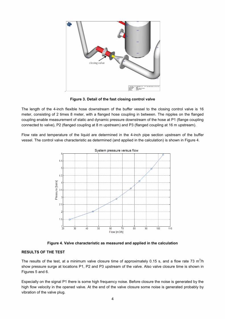
Figure 3. Detail of the fast closing control valve
The length of the 4-inch flexible hose downstream of the buffer vessel to the closing control valve is 16 meter, consisting of 2 times 8 meter, with a flanged hose coupling in between. The nipples on the flanged coupling enable measurement of static and dynamic pressure downstream of the hose at P1 (flange coupling connected to valve), P2 (flanged coupling at 8 m upstream) and P3 (flanged coupling at 16 m upstream).
Flow rate and temperature of the liquid are determined in the 4-inch pipe section upstream of the buffer vessel. The control valve characteristic as determined (and applied in the calculation) is shown in Figure 4.
Figure 4. Valve characteristic as measured and applied in the calculation
RESULTS OF THE TEST
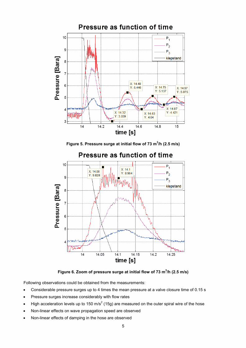
The results of the test, at a minimum valve closure time of approximately 0.15 s, and a flow rate 73 m3/h show pressure surge at locations P1, P2 and P3 upstream of the valve. Also valve closure time is shown in Figures 5 and 6.
Especially on the signal P1 there is some high frequency noise. Before closure the noise is generated by the high flow velocity in the opened valve. At the end of the valve closure some noise is generated probably by vibration of the valve plug.
5
Figure 5. Pressure surge at initial flow of 73 m3/h (2.5 m/s)
Figure 6. Zoom of pressure surge at initial flow of 73 m3/h (2.5 m/s)
Following observations could be obtained from the measurements:
• Considerable pressure surges up to 4 times the mean pressure at a valve closure time of 0.15 s
• Pressure surges increase considerably with flow rates
• High acceleration levels up to 150 m/s2 (15g) are measured on the outer spiral wire of the hose
• Non-linear effects on wave propagation speed are observed
• Non-linear effects of damping in the hose are observed

6
COMPARISON OF TEST AND SIMULATION RESULTS
As the wave propagation speed in the hose is an unknown parameter it has been tuned in the simulation such that the time delay between the first and second peak is reproduced correctly. Another parameter that has been tuned is the fanning friction factor of the hose. This parameter has been tuned such that the pressure losses over both hose sections comply with the measurements i.e. so that the initial pressures of P1, P2, and P3 are correctly reproduced.
In the next graphs the measured and simulated pressures at P1, P2, and P3 are shown in figure 7 and 8 respectively and compared individually in figures 9, 10, and 11. The initial flow rate for the case shown is 94 m3/h (3.2 m/s).
Figure 7. Measurement results for an initial flow of 94 m3/h (3.2 m/s)

7
Figure 8. Simulation result for an initial flow of 94 m3/ hr (3.2 m/s); Wave propagation speed in the hose = 205 m/s, Fanning friction factor = 0.04
Figure 9. Comparison measurement and simulation P3 (near vessel)

8
Figure 10. Comparison of measurement and simulation P2 (between the hose sections)
Figure 11. Comparison measurement and simulation P1 (near valve)
A large number of tests have been conducted, of which the results are not shown in this paper, which show a similar result.

9
SUMMARY OF RESULTS AND CONCLUSIONS
Measurements:
• For P1 high frequency at initial conditions probably caused by cavitation of valve;
• Also high frequency on the first peak may be caused by valve plug vibration;
• Lag time between consecutive peaks indicate variation of wave propagation speed in hose;
• Also damping in hose varies strongly and is clearly dependent on pressure or pressure variation.
Simulations: • Tuning the simulated wave propagation in the hose per case for the lag time between the first and
second peak leads to reproduction of the amplitude of the first peak;
• The initial pressure versus flow shows that the effective fanning friction factor for the hose is 0.04. This is ten times the default value we apply in simulations and complies with previous stationary pressure loss measurements;
• In comparison with the measurements the damping is much smaller in the model.
General:
• The multi composite hose shows a strongly non-linear behaviour. Both wave propagation speed and damping strongly vary with the flow condition. It is expected that both parameters depend on the momentary pressure or pressure variation;
• Fluid structure interaction in the hose is a dominant effect. Radial stretch of the hose causes the wave propagation speed to decrease dramatically. Transversal and axial response will strongly absorb wave energy and thus cause (non-linear damping;
• The wave propagation speed is very low and dependent on the pressure in the hose (see figure 12);
• The dynamic load on the hose differs completely from the static load. No conclusions can be drawn about failure of the hose by dynamic loads;
• In order to gain more insight in the mechanical behaviour and maximum allowable dynamic load a detailed mechanical model of the hose is needed. This model may also contribute to the modelling of the wave propagation speed and the damping.
Figure 14. The wave propagation speed in the hose as a function of the initial pressure deduced from the time delay between the first and second pressure peak

10
FINAL REMARKS
The results of the present investigations show that the hose behaves very different than is generally expected. The wave propagation speed is low, which means that the hose is stretched much more than generally assumed. What this means for the integrity of the hose needs to be further investigated.
Also the hose behaves highly non-linear. The wave propagation speed and friction depend strongly on the flow conditions. How exactly cannot be deduced from the present tests. Also the operating temperature might have a large effect on the parameters.
The present research has been conducted for one type and size of a composite hose, i.e. a 4-inch Gutteling hose. The behaviour of other sizes and other types of hoses should be investigated.
In view of the present results we recommend to be careful with the use of general design rules and with drawing conclusions from the results of fluid hammer calculations for off-loading systems with flexible hoses.
ACKNOWLEDGEMENT
We express our gratitude to Gutteling B.V. at Rotterdam (Netherlands) who supplied the LNG multi-composite hoses for the test. We also wish to thank the team that contributed to this research,
REFERENCES
1. Erik D. Nennie, Harry J.C. Korst, Knud Lunde, Rune Myklebust, “Water Hammer Likely Cause of Large Oil Spill in North Sea”, PVP2009-77770, Proceedings of the ASME 2009 Pressure Vessels and Piping Division Conference, July 26-30, 2009, Prague, Czech Republic.
2. “Guidelines for the Alleviation of Excessive Surge Pressures on ESD”, SIGTTO 1987, ISBN: 0 948691 40 9.
3. Standard EN 1474-part 2: “Installation and equipment for liquefied natural gas - Design and testing of transfer hoses ”Annex C “Surge pressure considerations for LNG hoses.”
4. Evert van Bokhorst “Lessons learned in the qualification of components and systems for LNG Offshore Transfer,” Proceedings conference Gastech 2011 Conference, Amsterdam March 2011.