instrument panel systems
TRANSCRIPT

D
D
R
D
I
D
tchosoptewtttp
mHaimigc
TJ INSTRUMENT PANEL SYSTEMS 8E - 1
INSTRUMENT PANEL SYSTEMS
CONTENTS
page page
ESCRIPTION AND OPERATIONACCESSORY RELAY . . . . . . . . . . . . . . . . . . . . . . 4INSTRUMENT CLUSTER . . . . . . . . . . . . . . . . . . . 2INSTRUMENT PANEL . . . . . . . . . . . . . . . . . . . . . 1INSTRUMENT PANEL CIGAR LIGHTER AND
POWER OUTLET . . . . . . . . . . . . . . . . . . . . . . . 3INSTRUMENT PANEL SYSTEM . . . . . . . . . . . . . 1IAGNOSIS AND TESTINGACCESSORY RELAY . . . . . . . . . . . . . . . . . . . . . . 9INSTRUMENT CLUSTER . . . . . . . . . . . . . . . . . . . 4INSTRUMENT PANEL CIGAR LIGHTER AND
POWER OUTLET . . . . . . . . . . . . . . . . . . . . . . 10EMOVAL AND INSTALLATIONACCESSORY RELAY . . . . . . . . . . . . . . . . . . . . . 18CLUSTER BEZEL . . . . . . . . . . . . . . . . . . . . . . . . 13
GLOVE BOX . . . . . . . . . . . . . . . . . . . . . . . . . . . 19GLOVE BOX COMPONENTS . . . . . . . . . . . . . . . 19GLOVE BOX LATCH STRIKER . . . . . . . . . . . . . 21HEADLAMP SWITCH . . . . . . . . . . . . . . . . . . . . 11INSTRUMENT CLUSTER . . . . . . . . . . . . . . . . . . 13INSTRUMENT CLUSTER COMPONENTS . . . . . 14INSTRUMENT PANEL ACCESSORY SWITCH
BEZEL . . . . . . . . . . . . . . . . . . . . . . . . . . . . . . 18INSTRUMENT PANEL ASSEMBLY . . . . . . . . . . 22INSTRUMENT PANEL BASE TRIM . . . . . . . . . . 24INSTRUMENT PANEL CENTER BEZEL . . . . . . . 17INSTRUMENT PANEL GRAB HANDLE . . . . . . . 21INSTRUMENT PANEL GRAB HANDLE BEZEL . 22INSTRUMENT PANEL TOP COVER . . . . . . . . . . 12KNEE BLOCKER . . . . . . . . . . . . . . . . . . . . . . . . 11STEERING COLUMN OPENING COVER . . . . . . 10
ESCRIPTION AND OPERATION
NSTRUMENT PANEL SYSTEM
ESCRIPTIONThe instrument panel serves as the command cen-
er of the vehicle, which necessarily makes it a veryomplex unit. The instrument panel is designed toouse the controls and monitors for standard andptional powertrains, climate control systems, audioystems, lighting systems, safety systems and manyther comfort or convenience items. The instrumentanel is also designed so that all of the various con-rols can be safely reached and the monitors can beasily viewed by the vehicle operator when driving,hile still allowing relative ease of access to each of
hese items for service. See the owner’s manual inhe vehicle glove box for more information on the fea-ures, use and operation of all of the instrumentanel components and systems.This group is responsible for covering service infor-ation for the vehicle instrument panel systems.owever, complete service information coverage forll of the systems and components housed in thenstrument panel in a single section of the service
anual would not be practical. Therefore, the servicenformation for any component will be found in theroup designated to cover the vehicle system that theomponent belongs to, even though the component is
mounted on or in the instrument panel. If you cannotlocate a listing for the component or system you areservicing in the table of contents for this group, or ifyou are uncertain as to which vehicle system a com-ponent belongs to, it is suggested that you refer tothe alphabetical Component and System Indexfound at the back of this service manual.
INSTRUMENT PANEL
DESCRIPTIONModular instrument panel construction allows all
of the gauges and controls to be serviced from thefront of the panel. In addition, most of the instru-ment panel electrical or heating and air conditioningcomponents can be accessed without complete instru-ment panel removal. If necessary, the instrumentpanel can be removed from the vehicle as an assem-bly.
Removal of the steering column opening cover andthe knee blocker provides access to the steering col-umn mounts, the steering column wiring, the gear-shift interlock mechanism, the headlamp switch, andmuch of the instrument panel wiring. Removal of theglove box provides access to the fuseblock module,additional instrument panel wiring, and many of theheating and air conditioning components.
Removal of the instrument cluster bezel allowsaccess to the cluster assembly. Removal of the cluster

aam
attib
mppah
I
D
muoniieor
i
l
tCb
8E - 2 INSTRUMENT PANEL SYSTEMS TJ
DESCRIPTION AND OPERATION (Continued)
ssembly allows access to the cluster illuminationnd indicator lamp bulbs, and more of the instru-ent panel wiring.Removal of the instrument panel center bezel
llows access to the radio, the heating and air condi-ioning controls, the power outlet or cigar lighter, andhe accessory switches. The power outlet/cigar lighters serviced only as a unit with the accessory switchezel.A bezel on each outboard end of the lower instru-ent panel is removed to service the instrument
anel speakers. Removal of the complete instrumentanel is required for service of the passenger sideirbag module and most internal components of theeating and air conditioning system housing.
NSTRUMENT CLUSTER
ESCRIPTIONA single instrument cluster is offered on thisodel. This cluster is an electromechanical unit thattilizes integrated circuitry and information carriedn the Chrysler Collision Detection (CCD) data busetwork for control of all gauges and many of the
ndicator lamps. This cluster also incorporates a dig-tal Vacuum Fluorescent Display (VFD) for the odom-ter/trip odometer display functions. Some variationsf this cluster exist due to optional equipment andegulatory requirements.The cluster includes the following analog gauges:• Coolant temperature gauge• Fuel gauge• Oil pressure gauge• Speedometer• Tachometer• Voltmeter.This cluster also includes provisions for the follow-
ng indicator lamps:• Airbag indicator lamp• Anti-lock Brake System (ABS) lamp• Brake warning lamp• Check gauges lamp• Cruise-on indicator lamp• Four-wheel drive indicator lamp• Headlamp high beam indicator lamp• Low fuel warning lamp• Malfunction indicator (Check Engine) lamp• Seat belt reminder lamp• Sentry Key Immobilizer System (SKIS) indicator
amp• Turn signal indicator lamps• Upshift indicator lamp (manual transmission).The instrument cluster circuitry has a self-diagnos-
ic actuator test capability, which will test each of theCD bus message-controlled functions of the clustery lighting the appropriate indicator lamps and posi-
tioning the gauge needles at several predeterminedlocations on the gauge faces in a prescribed sequence.For more information on this function, refer toInstrument Cluster in the Diagnosis and Testingsection of this group.
The instrument cluster circuitry also integrates achime tone generator and a timer circuit. Theseitems replace the chime or buzzer module, and theseparate timer circuit for the rear window defoggersystem. Refer to Chime Warning System in theDescription and Operation section of Group 8U -Chime/Buzzer Warning Systems for more informationon the chime functions of the instrument cluster.Refer to Rear Window Defogger System in theDescription and Operation section of Group 8N -Electrically Heated Systems for more information onthe timer function of the instrument cluster.
The instrument cluster for this model is servicedonly as a complete unit. If a cluster gauge or thecluster circuit board are faulty, the entire clustermust be replaced. The cluster lens, the cluster hoodand mask, the rear cluster housing cover, the odom-eter reset knob boot and the incandescent lamp bulbsand holders are available for service replacement.
OPERATION
GAUGEWith the ignition switch in the On or Start posi-
tions, voltage is supplied to all gauges through theinstrument cluster electronic circuit board. With theignition switch in the Off position, voltage is not sup-plied to the gauges. The gauges do not accuratelyindicate any vehicle condition unless the ignitionswitch is in the On or Start positions.
All of the instrument cluster gauges, except theodometer, are air core magnetic units. Two fixed elec-tromagnetic coils are located within the gauge. Thesecoils are wrapped at right angles to each otheraround a movable permanent magnet. The movablemagnet is suspended within the coils on one end of ashaft. The gauge needle is attached to the other endof the shaft.
One of the coils has a fixed current flowingthrough it to maintain a constant magnetic fieldstrength. Current flow through the second coilchanges, which causes changes in its magnetic fieldstrength. The current flowing through the second coilis changed by the instrument cluster electronic cir-cuitry in response to messages received on theChrysler Collision Detection (CCD) data bus network.
The gauge needle moves as the movable permanentmagnet aligns itself to the changing magnetic fieldscreated around it by the electromagnets. The instru-ment cluster circuitry is programmed to move all ofthe gauge needles back to the low end of their respec-

tO
I
tcicon
lhlcTm(tt
ta
C
taIhcndf
mwiaFl(hf
tih
IP
D
o
TJ INSTRUMENT PANEL SYSTEMS 8E - 3
DESCRIPTION AND OPERATION (Continued)
ive scales after the ignition switch is turned to theff position.
NDICATOR LAMPIndicator lamps are located in the instrument clus-
er and are served by the cluster circuit board andonnectors. Many of the indicator lamps in thenstrument cluster are controlled by the instrumentluster circuitry in response to messages receivedver the Chrysler Collision Detection (CCD) data busetwork.The anti-lock brake system lamp, brake warning
amp, four-wheel drive indicator lamp, headlampigh beam indicator lamp, and turn signal indicator
amps are hard wired. The seat belt reminder lamp isontrolled by the instrument cluster programming.he instrument cluster circuitry uses CCD data busessages from the Powertrain Control Module
PCM), Airbag Control Module (ACM), and the Sen-ry Key Immobilizer Module (SKIM) to control all ofhe remaining indicator lamps.
Each of the indicator lamps in the instrument clus-er uses incandescent bulbs and holders, which arevailable for service replacement.
LUSTER ILLUMINATION LAMPThe cluster illumination lamps are hard wired in
he instrument cluster. When the park or head lampsre turned on, the cluster illumination lamps light.llumination brightness is adjusted by rotating theeadlamp switch knob (clockwise to dim, counter-lockwise to brighten). The instrument cluster illumi-ation lamps receive battery feed from the panelimmer rheostat in the headlamp switch through ause in the fuseblock module.
The instrument cluster electronic circuitry alsoonitors the cluster illumination lamp dimming levelhenever the park or head lamps are turned on. The
nstrument cluster electronic circuitry responds bydjusting the dimming level of the odometer Vacuumluorescent Display (VFD), and sending dimming
evel messages over the Chrysler Collision DetectionCCD) data bus network. When the park lamps oreadlamps are turned off, the VFD is illuminated atull brightness for improved daylight visibility.
Each of the cluster illumination lamps is located onhe instrument cluster circuit board. Each clusterllumination lamp has a replaceable bulb and bulbolder.
NSTRUMENT PANEL CIGAR LIGHTER ANDOWER OUTLET
ESCRIPTIONAn accessory power outlet is standard equipment
n this model. The power outlet is installed in the
instrument panel accessory switch bezel, which islocated near the bottom of the instrument panel cen-ter bezel area, next to the ash receiver. A plastic capsnaps into the power outlet base when the power out-let is not in use. A cigar lighter that fits into thepower outlet is a dealer-installed option.
The cigar lighter/power outlet base is serviced onlyas a part of the accessory switch bezel unit. If thebase is faulty or damaged, the accessory switch bezelunit must be replaced. The cigar lighter knob andheating element unit is available for service. Thiscomponent cannot be repaired and, if faulty or dam-aged, it must be replaced.
OPERATIONThe cigar lighter/power outlet base or receptacle
shell is connected to ground, and an insulated con-tact in the bottom of the shell is connected to batterycurrent. The power outlet receives battery voltagefrom a fuse in the Power Distribution Center (PDC)through the accessory relay only when the ignitionswitch is in the Accessory or On positions. Refer toAccessory Relay in the Description and Operationsection of this group for more information on thiscomponent.
The cigar lighter knob and heating element areencased within a spring-loaded housing, which alsofeatures a sliding protective heat shield. When theknob and heating element are inserted in the recep-tacle shell, the heating element resistor coil isgrounded through its housing to the receptacle shell.If the cigar lighter knob is pushed inward, the heatshield slides up toward the knob exposing the heat-ing element, and the heating element extends fromthe housing toward the insulated contact in the bot-tom of the receptacle shell.
Two small spring-clip retainers are located oneither side of the insulated contact inside the bottomof the receptacle shell. These clips engage and holdthe heating element of the dealer-installed cigarlighter against the insulated contact long enough forthe resistor coil to heat up. When the heating ele-ment is engaged with the contact, battery currentcan flow through the resistor coil to ground, causingthe resistor coil to heat.
When the resistor coil becomes sufficiently heated,excess heat radiates from the heating element caus-ing the spring-clips to expand. Once the spring-clipsexpand far enough to release the heating element,the spring-loaded housing forces the knob and heat-ing element to pop back outward to their relaxedposition. When the cigar lighter knob and elementare pulled out of the receptacle shell, the protectiveheat shield slides downward on the housing so thatthe heating element is recessed and shielded aroundits circumference for safety.

A
D
tatphnmp
OIcf
a
O
rar(tcac
snnrp
D
I
ei(iirDtFCg
WB
8E - 4 INSTRUMENT PANEL SYSTEMS TJ
DESCRIPTION AND OPERATION (Continued)
CCESSORY RELAY
ESCRIPTIONThe accessory relay is an electromechanical device
hat switches fused battery current to the standardccessory power outlet or optional cigar lighter whenhe ignition switch is turned to the Accessory or Onositions. The accessory relay is located in a wirearness connector that is secured to the 100-way con-ector bracket under the driver side of the instru-ent panel, near the cowl side inner panel in the
assenger compartment.The accessory relay is a International Standardsrganization (ISO) relay. Relays conforming to the
SO specifications have common physical dimensions,urrent capacities, terminal patterns, and terminalunctions.
The accessory relay cannot be repaired or adjustednd, if faulty or damaged, it must be replaced.
PERATIONThe ISO relay consists of an electromagnetic coil, a
esistor or diode, and three (two fixed and one mov-ble) electrical contacts. The movable (common feed)elay contact is held against one of the fixed contactsnormally closed) by spring pressure. When the elec-romagnetic coil is energized, it draws the movableontact away from the normally closed fixed contact,nd holds it against the other (normally open) fixedontact.When the electromagnetic coil is de-energized,
pring pressure returns the movable contact to theormally closed position. The resistor or diode is con-ected in parallel with the electromagnetic coil in theelay, and helps to dissipate voltage spikes that areroduced when the coil is de-energized.
IAGNOSIS AND TESTING
NSTRUMENT CLUSTERIf all of the gauges and/or indicator lamps are inop-
rative, perform the Preliminary Diagnosis. If anndividual gauge or Chrysler Collision DetectionCCD) data bus message-controlled indicator lamp isnoperative, go directly to the Actuator Test. If anndividual hard wired indicator lamp is inoperative,efer to Instrument Cluster - Hard Wired Lampiagnosis in the Diagnosis and Testing section of
his group for the procedures to diagnosis that lamp.or complete circuit diagrams, refer to Instrumentluster in the Contents of Group 8W - Wiring Dia-rams.
ARNING: ON VEHICLES EQUIPPED WITH AIR-AGS, REFER TO GROUP 8M - PASSIVE
RESTRAINT SYSTEMS BEFORE ATTEMPTING ANYSTEERING WHEEL, STEERING COLUMN, ORINSTRUMENT PANEL COMPONENT DIAGNOSIS ORSERVICE. FAILURE TO TAKE THE PROPER PRE-CAUTIONS COULD RESULT IN ACCIDENTAL AIR-BAG DEPLOYMENT AND POSSIBLE PERSONALINJURY.
PRELIMINARY DIAGNOSIS(1) If the indicator lamps operate, but none of the
gauges operate, go to Step 2. If all of the gauges andthe CCD data bus message-controlled indicator lampsare inoperative, go to Step 5.
(2) Check the fused B(+) fuse in the Power Distri-bution Center (PDC). If OK, go to Step 3. If not OK,repair the shorted circuit or component as requiredand replace the faulty fuse.
(3) Check for battery voltage at the fused B(+) fusein the PDC. If OK, go to Step 4. If not OK, repair theopen fused B(+) circuit to the battery as required.
(4) Disconnect and isolate the battery negativecable. Remove the instrument cluster. Connect thebattery negative cable. Check for battery voltage atthe fused B(+) circuit cavity of the instrument clusterwire harness connector A. If OK, refer to Instru-ment Cluster - Actuator Test in the Diagnosis andTesting section of this group. If not OK, repair theopen fused B(+) circuit to the fuse in the PDC asrequired.
(5) Check the fused ignition switch output (run/start) fuse in the fuseblock module. If OK, go to Step6. If not OK, repair the shorted circuit or componentas required and replace the faulty fuse.
(6) Turn the ignition switch to the On position andcheck for battery voltage at the fused ignition switchoutput (run/start) fuse in the fuseblock module. IfOK, go to Step 7. If not OK, repair the open fusedignition switch output (run/start) circuit to the igni-tion switch as required.
(7) Turn the ignition switch to the Off position.Disconnect and isolate the battery negative cable.Install the instrument cluster. Connect the batterynegative cable. Turn the ignition switch to the Onposition. Set the park brake. The red brake warninglamp should light. If OK, go to Step 8. If not OK, goto Step 9.
(8) Turn the ignition switch to the Off position.Turn on the park lamps and adjust the panel lampsdimmer rheostat in the headlamp switch to the fullbright position. The cluster illumination lampsshould light. If OK, refer to Instrument Cluster -Actuator Test in the Diagnosis and Testing sectionof this group. If not OK, go to Step 10.
(9) Turn the ignition switch to the Off position.Disconnect and isolate the battery negative cable.Remove the instrument cluster. Connect the battery

nptirDO(a
ctigtDOr
A
itdcmoigal
febbleto
otcmnrO
dsdhecc
TJ INSTRUMENT PANEL SYSTEMS 8E - 5
DIAGNOSIS AND TESTING (Continued)
egative cable. Turn the ignition switch to the Onosition. Check for battery voltage at the fused igni-ion switch output (run/start) circuit cavity of thenstrument cluster wire harness connector A. If OK,efer to Instrument Cluster - Actuator Test in theiagnosis and Testing section of this group. If notK, repair the open fused ignition switch output
run/start) circuit to the fuse in the fuseblock modules required.(10) Disconnect and isolate the battery negative
able. Remove the instrument cluster. Check for con-inuity between the ground circuit cavity of thenstrument cluster wire harness connector A and aood ground. There should be continuity. If OK, refero Instrument Cluster - Actuator Test in theiagnosis and Testing section of this group. If notK, repair the open ground circuit to ground as
equired.
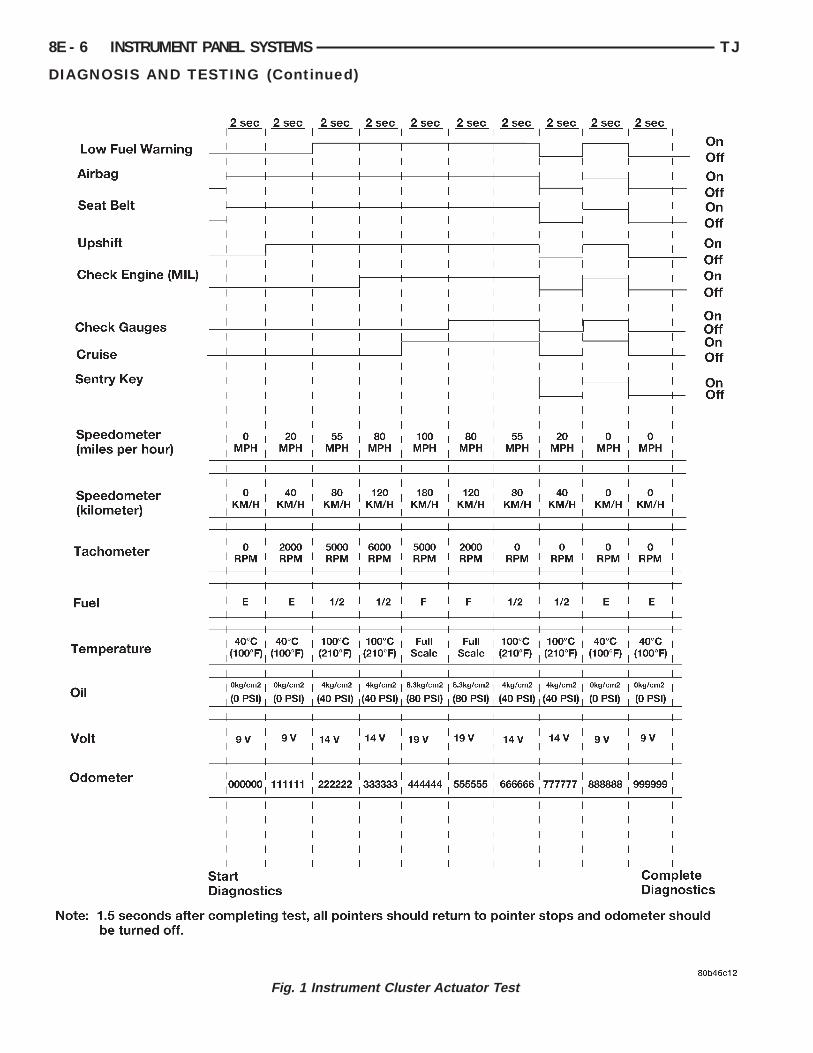
CTUATOR TESTThe instrument cluster actuator test will put the
nstrument cluster into its self-diagnostic mode. Inhis mode the instrument cluster can perform a self-iagnostic test that will confirm that the instrumentluster circuitry, the gauges, and the CCD data busessage controlled indicator lamps are capable of
perating as designed. During the actuator test thenstrument cluster circuitry will position each of theauge needles at various specified calibration points,nd turn all of the CCD data bus message-controlledamps on and off at specified time intervals (Fig. 1).
Successful completion of the actuator test will con-irm that the instrument cluster is operational. How-ver, there may still be a problem with the CCD dataus, the Powertrain Control Module (PCM), the Air-ag Control Module (ACM), the Sentry Key Immobi-izer Module (SKIM) or the inputs to one of theselectronic control modules. Use a DRB scan tool andhe proper Diagnostic Procedures manual for testingf these components.If an individual gauge does not respond properly,
r does not respond at all during the actuator test,he instrument cluster should be removed. However,heck that the gauge mounting screws on the instru-ent cluster electronic circuit board for proper tight-ess before considering instrument clustereplacement. If the gauge mounting screws checkK, replace the faulty cluster.If an individual indicator lamp does not illuminate
uring the actuator test, the instrument clusterhould be removed. However, check that the incan-escent lamp bulb is not faulty and that the bulbolder is properly installed on the instrument clusterlectronic circuit board before considering instrumentluster replacement. If the bulb and bulb holderheck OK, replace the faulty instrument cluster.
(1) Begin the test with the ignition switch in theOff position.
(2) Depress the trip odometer reset button.(3) While holding the trip odometer reset button
depressed, turn the ignition switch to the On posi-tion, but do not start the engine.
(4) Release the trip odometer reset button.(5) Compare the operation of the suspect gauge(s)
and/or indicator lamp(s) with the Instrument ClusterActuator Test chart (Fig. 1).
(6) The instrument cluster will automatically exitthe self-diagnostic mode and return to normal opera-tion at the completion of the test, if the ignitionswitch is turned to the Off position during the test,or if a vehicle speed message indicating that thevehicle is moving is received from the PCM on theCCD data bus during the test.
(7) Go back to Step 1 to repeat the test, ifrequired.
HARD WIRED LAMP DIAGNOSISEach of the lamps found in this section depends
upon a hard wired circuit input to the instrumentcluster for proper operation. The following procedureswill help to diagnose conditions that may cause aninoperative hard wired lamp circuit condition.
WARNING: ON VEHICLES EQUIPPED WITH AIR-BAGS, REFER TO GROUP 8M - PASSIVERESTRAINT SYSTEMS BEFORE ATTEMPTING ANYSTEERING WHEEL, STEERING COLUMN, ORINSTRUMENT PANEL COMPONENT DIAGNOSIS ORSERVICE. FAILURE TO TAKE THE PROPER PRE-CAUTIONS COULD RESULT IN ACCIDENTAL AIR-BAG DEPLOYMENT AND POSSIBLE PERSONALINJURY.
ANTI-LOCK BRAKE SYSTEM LAMPThe diagnosis found here addresses an inoperative
Anti-lock Brake System (ABS) lamp condition. If theABS lamp stays on with the ignition switch in theOn position, or comes on and stays on while driving,refer to Antilock Brakes in the Diagnosis and Test-ing section of Group 5 - Brakes for diagnosis. If noABS problem is found, the following procedure willhelp locate a short or open in the ABS lamp circuit.For complete circuit descriptions, refer to Instru-ment Cluster in the Contents of Group 8W - WiringDiagrams.
(1) Check the fused ignition switch output (run/start) fuse in the fuseblock module. If OK, go to Step2. If not OK, repair the shorted circuit or componentas required and replace the faulty fuse.
(2) Turn the ignition switch to the On position.Check for battery voltage at the fused ignition switchoutput (run/start) fuse in the fuseblock module. If
8E - 6 INSTRUMENT PANEL SYSTEMS TJ
DIAGNOSIS AND TESTING (Continued)
r Actuator Test
Fig. 1 Instrument Cluste
Oit
DRnpbctfct
DDhAigti
ichriCc
B
blpwcseiBplcCg
s2a
CoO
TJ INSTRUMENT PANEL SYSTEMS 8E - 7
DIAGNOSIS AND TESTING (Continued)
K, go to Step 3. If not OK, repair the open fusedgnition switch output (run/start) circuit to the igni-ion switch as required.
(3) Turn the ignition switch to the Off position.isconnect and isolate the battery negative cable.emove the instrument cluster. Connect the batteryegative cable. Turn the ignition switch to the Onosition and within five seconds check for continuityetween the ABS warning indicator driver circuitavity of the instrument cluster wire harness connec-or A and a good ground. There should be continuityor five seconds after ignition On, and then an openircuit. If OK, replace the faulty bulb. If not OK, goo Step 4.
(4) Turn the ignition switch to the Off position.isconnect and isolate the battery negative cable.isconnect the Controller Anti-lock Brake (CAB) wirearness connector. Check for continuity between theBS warning indicator driver circuit cavity of the
nstrument cluster wire harness connector A and aood ground. There should be no continuity. If OK, goo Step 5. If not OK, repair the shorted ABS warningndicator driver circuit as required.
(5) Check for continuity between the ABS warningndicator driver circuit cavities of the instrumentluster wire harness connector A and the CAB wirearness connector. There should be continuity. If OK,efer to Antilock Brakes in the Diagnosis and Test-ng section of Group 5 - Brakes for diagnosis of theAB. If not OK, repair the open ABS warning indi-ator driver circuit as required.
RAKE WARNING LAMPThe diagnosis found here addresses an inoperative
rake warning lamp condition. If the brake warningamp stays on with the ignition switch in the Onosition and the park brake released, or comes onhile driving, refer to Base Brake System for vehi-
les not equipped with the four wheel anti-lock brakeystem, or refer to Antilock Brakes for vehiclesquipped with the four wheel anti-lock brake systemn the Diagnosis and Testing section of Group 5 -rakes for further diagnosis. If no brake systemroblem is found, the following procedure will helpocate a short or open circuit, or a faulty switch. Foromplete circuit diagrams, refer to Instrumentluster in the Contents of Group 8W - Wiring Dia-rams.(1) Check the fused ignition switch output (run/
tart) fuse in the fuseblock module. If OK, go to Step. If not OK, repair the shorted circuit or components required and replace the faulty fuse.(2) Turn the ignition switch to the On position.heck for battery voltage at the fused ignition switchutput (run/start) fuse in the fuseblock module. IfK, go to Step 3. If not OK, repair the open fused
ignition switch output (run/start) circuit to the igni-tion switch as required.
(3) Turn the ignition switch to the Off position.Disconnect and isolate the battery negative cable.Disconnect the wire harness connector at the parkbrake switch. With the park brake released, check forcontinuity between the park brake switch terminaland a good ground. There should be no continuity. IfOK, go to Step 4. If not OK, adjust or replace thefaulty park brake switch.
(4) Disconnect the wire harness connector at thebrake warning switch. Check for continuity betweenthe two terminals of the brake warning switch. Thereshould be continuity. If OK, go to Step 5. If not OK,replace the faulty brake warning switch.
(5) Check for continuity between each of the twobrake warning switch terminals and a good ground.In each case, there should be no continuity. If OK, goto Step 6. If not OK, replace the faulty brake warn-ing switch.
(6) With both the park brake switch and the brakewarning switch wire harness connectors still discon-nected, check for continuity between the red brakewarning indicator driver circuit cavity of the parkbrake switch wire harness connector and a goodground. There should be no continuity. If OK, go toStep 7. If not OK, repair the shorted red brake warn-ing indicator driver circuit as required.
(7) With the ignition switch held in the Start posi-tion, check for continuity between the red brakewarning indicator driver circuit cavity of the parkbrake switch wire harness connector and a goodground. There should be continuity. If OK, go to Step8. If not OK, repair the open red brake warning indi-cator driver circuit to the ignition switch as required.
(8) Turn the ignition switch to the Off position.Remove the instrument cluster. Check for continuitybetween the red brake warning indicator driver cir-cuit cavity of the instrument cluster wire harnessconnector A and a good ground. There should be nocontinuity. If OK, go to Step 9. If not OK, repair theshorted red brake warning indicator driver circuit asrequired.
(9) Check for continuity between the red brakewarning indicator driver circuit cavities of the instru-ment cluster wire harness connector A and the brakewarning switch wire harness connector. There shouldbe continuity. If OK, replace the faulty bulb. If notOK, repair the open red brake warning indicatordriver circuit as required.
CLUSTER ILLUMINATION LAMPThe diagnosis found here addresses an inoperative
instrument cluster illumination lamp condition. Ifthe problem being diagnosed includes inoperativeexterior lighting controlled by the headlamp switch,

tlasdfsIducoirG
fra
scCfsmzohrTh
clfptCbrs
fcscCdcfhl
F
fpbltNttfid
8E - 8 INSTRUMENT PANEL SYSTEMS TJ
DIAGNOSIS AND TESTING (Continued)
hat system needs to be repaired first. If the exterioramps controlled by the headlamp switch are inoper-tive, refer to Headlamp Diagnosis in the Diagno-is and Testing section of Group 8L - Lamps foriagnosis. If no exterior lighting system problems areound, the following procedure will help locate ahort or open in the cluster illumination lamp circuit.f the problem being diagnosed involves a lack ofimming control for the odometer/trip odometer Vac-um Fluorescent Display (VFD), but all of the otherluster illumination lamps can be dimmed, repair thepen headlamp switch output circuit input to thenstrument cluster. For complete circuit diagrams,efer to Instrument Cluster in the Contents ofroup 8W - Wiring Diagrams.(1) Check the panel lamps dimmer fuse in the
useblock module. If OK, go to Step 2. If not OK,epair the shorted circuit or component as requirednd replace the faulty fuse.(2) Turn the park lamps on with the headlamp
witch. Rotate the headlamp switch knob counter-lockwise to just before the interior lamps detent.heck for battery voltage at the panel lamps dimmer
use in the fuseblock module. Rotate the headlampwitch knob clockwise while observing the test volt-eter. The reading should go from battery voltage to
ero volts. If OK, go to Step 3. If not OK, repair thepen panel lamps dimmer switch signal circuit to theeadlamp switch as required. If the circuit tests OK,efer to Headlamp Diagnosis in the Diagnosis andesting section of Group 8L - Lamps to diagnose theeadlamp switch.(3) Disconnect and isolate the battery negative
able. Remove the instrument cluster. Turn the head-amp switch off. Remove the panel lamps dimmeruse from the fuseblock module. Probe the fusedanel lamps dimmer switch signal circuit cavity ofhe instrument cluster wire harness connector A.heck for continuity to a good ground. There shoulde no continuity. If OK, go to Step 4. If not OK,epair the shorted fused panel lamps dimmer switchignal circuit as required.(4) Install the panel lamps dimmer fuse in the
useblock module. Connect the battery negativeable. Turn the park lamps on with the headlampwitch. Rotate the headlamp switch knob counter-lockwise to just before the interior lamps detent.heck for battery voltage at the fused panel lampsimmer switch signal circuit cavity of the instrumentluster wire harness connector A. If OK, replace theaulty cluster illumination lamp bulb(s) and bulbolder(s). If not OK, repair the open fused panel
amps dimmer switch signal circuit as required.
OUR-WHEEL DRIVE INDICATOR LAMPThe diagnosis found here addresses an inoperative
our-wheel drive indicator lamp condition. If theroblem being diagnosed is related to lamp accuracy,e certain to confirm that the problem is with theamp or switch and not with a damaged or inopera-ive transfer case or transfer case linkage. Refer toV231 Diagnosis in the Diagnosis and Testing sec-
ion of Group 21 - Transmission for more informa-ion. If no transfer case problem is found, theollowing procedure will help locate a short or openn the indicator lamp circuit. For complete circuitiagrams, refer to Instrument Cluster in Group 8W
- Wiring Diagrams.(1) Check the fused ignition switch output (run/
start) fuse in the fuseblock module. If OK, go to Step2. If not OK, repair the shorted circuit or componentas required and replace the faulty fuse.
(2) Turn the ignition switch to the On position.Check for battery voltage at the fused ignition switchoutput (run/start) fuse in the fuseblock module. IfOK, go to Step 3. If not OK, repair the open fusedignition switch output (run/start) circuit to the igni-tion switch as required.
(3) Turn the ignition switch to the Off position.Disconnect and isolate the battery negative cable.Disconnect the transfer case switch wire harness con-nector. Check for continuity between the ground cir-cuit cavity of the transfer case switch wire harnessconnector and a good ground. There should be conti-nuity. If OK, go to Step 4. If not OK, repair the openground circuit to ground as required.
(4) Connect the battery negative cable. Turn theignition switch to the On position. Install a jumperwire between the part time four wheel drive indicatorlamp driver circuit cavity of the transfer case switchwire harness connector and a good ground. The four-wheel drive indicator lamp should light. If OK,replace the faulty transfer case switch. If not OK, goto Step 5.
(5) Turn the ignition switch to the Off position.Disconnect and isolate the battery negative cable.Remove the instrument cluster. With the transfercase switch wire harness connector still disconnected,check for continuity between the part time fourwheel drive indicator lamp driver circuit cavity of theinstrument cluster wire harness connector B and agood ground. There should be no continuity. If OK, goto Step 6. If not OK, repair the shorted part timefour wheel drive indicator lamp driver circuit asrequired.
(6) Check for continuity between the part timefour wheel drive indicator lamp driver circuit cavitiesof the instrument cluster wire harness connector Band the transfer case switch wire harness connector.There should be continuity. If OK, replace the faulty

bd
H
hphs-hpirG
c
hmairhd
T
ttasihiirG
c
twbshrtl(h
A
hn
TJ INSTRUMENT PANEL SYSTEMS 8E - 9
DIAGNOSIS AND TESTING (Continued)
ulb. If not OK, repair the open part time four wheelrive indicator lamp driver circuit as required.
EADLAMP HIGH BEAM INDICATOR LAMPThe diagnosis found here addresses an inoperative
eadlamp high beam indicator lamp condition. If theroblem being diagnosed is related to inoperativeeadlamp high beams, refer to Headlamp Diagno-is in the Diagnosis and Testing section of Group 8LLamps for diagnosis of the headlamp system. If noeadlamp system problems are found, the followingrocedure will help locate an open in the high beamndicator lamp circuit. For complete circuit diagrams,efer to Instrument Cluster in the Contents ofroup 8W - Wiring Diagrams.(1) Disconnect and isolate the battery negative
able. Remove the instrument cluster.(2) Connect the battery negative cable. Turn the
eadlamps on and select the high beams with theulti-function switch stalk. Check for battery voltage
t the high beam indicator driver circuit cavity of thenstrument cluster wire harness connector A. If OK,eplace the faulty bulb. If not OK, repair the openigh beam indicator driver circuit to the headlampimmer (multi-function) switch as required.
URN SIGNAL INDICATOR LAMPThe diagnosis found here addresses an inoperative
urn signal indicator lamp condition. For any otherurn signal problem, refer to Turn Signal and Haz-rd Warning Systems in the Diagnosis and Testingection of Group 8J - Turn Signal and Hazard Warn-ng Systems for further diagnosis. If no turn signal orazard warning system problem is found, the follow-
ng procedure will help locate a short or open in thendicator lamp circuit. For complete circuit diagrams,efer to Instrument Cluster in the Contents ofroup 8W - Wiring Diagrams.(1) Disconnect and isolate the battery negative
able. Remove the instrument cluster.(2) Connect the battery negative cable. Activate
he hazard warning system by moving the hazardarning switch button to the On position. Check forattery voltage at the inoperative (right or left) turnignal circuit cavity of the instrument cluster wirearness connector (connector A - left, or connector B -ight). There should be a switching (on and off) bat-ery voltage signal. If OK, replace the faulty (right oreft) indicator lamp bulb. If not OK, repair the openright or left) turn signal circuit to the turn signal/azard warning (multi-function) switch as required.
CCESSORY RELAYThe accessory relay (Fig. 2) is located in a wire
arness connector that is secured to the 100-way con-ector bracket under the driver side of the instru-
ment panel, near the cowl side inner panel in thepassenger compartment. For complete circuit dia-grams, refer to Horn/Cigar Lighter in the Contentsof Group 8W - Wiring Diagrams.
WARNING: ON VEHICLES EQUIPPED WITH AIR-BAGS, REFER TO GROUP 8M - PASSIVERESTRAINT SYSTEMS BEFORE ATTEMPTING ANYSTEERING WHEEL, STEERING COLUMN, ORINSTRUMENT PANEL COMPONENT DIAGNOSIS ORSERVICE. FAILURE TO TAKE THE PROPER PRE-CAUTIONS COULD RESULT IN ACCIDENTAL AIR-BAG DEPLOYMENT AND POSSIBLE PERSONALINJURY.
(1) Remove the accessory relay from its wire har-ness connector. Refer to Accessory Relay in theRemoval and Installation section of this group for theprocedures.
(2) A relay in the de-energized position shouldhave continuity between terminals 87A and 30, andno continuity between terminals 87 and 30. If OK, goto Step 3. If not OK, replace the faulty relay.
(3) Resistance between terminals 85 and 86 (elec-tromagnet) should be 75 6 5 ohms. If OK, go to Step4. If not OK, replace the faulty relay.
(4) Connect a battery to terminals 85 and 86.There should now be continuity between terminals30 and 87, and no continuity between terminals 87Aand 30. If OK, perform the Relay Circuit Test thatfollows. If not OK, replace the faulty relay.
RELAY CIRCUIT TEST(1) The relay common feed terminal (30) is con-
nected to battery voltage and should be hot at alltimes. Check for battery voltage at the fused B(+) cir-cuit cavity of the accessory relay wire harness con-nector. If OK, go to Step 2. If not OK, repair thefused B(+) circuit to the fuse in the Power Distribu-tion Center (PDC) as required.
Fig. 2 Accessory Relay
cb
ngteccspOso
twsgc
tfsivcnsa
IP
gD
WBRSISCBI
krirc3
8E - 10 INSTRUMENT PANEL SYSTEMS TJ
DIAGNOSIS AND TESTING (Continued)
(2) The relay normally closed terminal (87A) isonnected to terminal 30 in the de-energized position,ut is not used for this application. Go to Step 3.(3) The relay normally open terminal (87) is con-
ected to the common feed terminal (30) in the ener-ized position. This terminal supplies battery voltageo the cigar lighter or power outlet when the relay isnergized by the ignition switch. There should beontinuity between the accessory relay wire harnessonnector cavity for relay terminal 87 and the acces-ory relay output circuit cavity in the cigar lighter orower outlet wire harness connector at all times. IfK, go to Step 4. If not OK, repair the open acces-
ory relay output circuit to the cigar lighter or powerutlet wire harness connector as required.(4) The coil battery terminal (86) is connected to
he electromagnet in the relay. The accessory relayire harness connector cavity for this terminal
hould have continuity to ground at all times. If OK,o to Step 5. If not OK, repair the open ground cir-uit to ground as required.(5) The coil ground terminal (85) is connected to
he electromagnet in the relay. It receives batteryeed to energize the accessory relay when the ignitionwitch is in the Accessory or On positions. Turn thegnition switch to the On position. Check for batteryoltage at the fused ignition switch output (acc/run)ircuit cavity of the accessory relay wire harness con-ector. If not OK, repair the open fused ignitionwitch output (acc/run) circuit to the ignition switchs required.
NSTRUMENT PANEL CIGAR LIGHTER ANDOWER OUTLETFor complete circuit diagrams, refer to Horn/Ci-
ar Lighter in the Contents of Group 8W - Wiringiagrams.
ARNING: ON VEHICLES EQUIPPED WITH AIR-AGS, REFER TO GROUP 8M - PASSIVEESTRAINT SYSTEMS BEFORE ATTEMPTING ANYTEERING WHEEL, STEERING COLUMN, OR
NSTRUMENT PANEL COMPONENT DIAGNOSIS ORERVICE. FAILURE TO TAKE THE PROPER PRE-AUTIONS COULD RESULT IN ACCIDENTAL AIR-AG DEPLOYMENT AND POSSIBLE PERSONAL
NJURY.
(1) Remove the protective cap or the cigar lighternob and element from the cigar lighter/power outleteceptacle shell. Check for continuity between thenside circumference of the cigar lighter/power outleteceptacle shell and a good ground. there should beontinuity. If OK, go to Step 2. If not OK, go to Step.
(2) Turn the ignition switch to the On position.Check for battery voltage at the insulated contactlocated at the back of the cigar lighter/power outletreceptacle shell. If OK, replace the faulty cigarlighter knob and element. If not OK, go to Step 3.
(3) Turn the ignition switch to the Off position.Disconnect and isolate the battery negative cable.Remove the instrument panel accessory switch bezel.Check for continuity between the ground circuit cav-ity of the cigar lighter/power outlet wire harness con-nector and a good ground. There should becontinuity. If OK, go to Step 4. If not OK, repair theopen ground circuit to ground as required.
(4) Connect the battery negative cable. Turn theignition switch to the Accessory or On positions.Check for battery voltage at the accessory relay out-put circuit cavity of the cigar lighter/power outletwire harness connector. If OK, replace the faultyaccessory switch bezel unit. If not OK, refer toAccessory Relay in the Diagnosis and Testing sec-tion of this group for further diagnosis.
REMOVAL AND INSTALLATION
STEERING COLUMN OPENING COVER
WARNING: ON VEHICLES EQUIPPED WITH AIR-BAGS, REFER TO GROUP 8M - PASSIVERESTRAINT SYSTEMS BEFORE ATTEMPTING ANYSTEERING WHEEL, STEERING COLUMN, ORINSTRUMENT PANEL COMPONENT DIAGNOSIS ORSERVICE. FAILURE TO TAKE THE PROPER PRE-CAUTIONS COULD RESULT IN ACCIDENTAL AIR-BAG DEPLOYMENT AND POSSIBLE PERSONALINJURY.
REMOVAL(1) Disconnect and isolate the battery negative
cable.(2) If the vehicle is so equipped, move the tilt
steering column to the fully raised position.(3) Remove the knob and shaft from the headlamp
switch. Refer to Headlamp Switch in the Removaland Installation section of this group for the proce-dures.
(4) Remove the two screws that secure the steeringcolumn opening cover to the instrument panel (Fig.3).
(5) Pull the upper edge of the steering columnopening cover straight back and down away from theinstrument panel as far as possible.
(6) Rock the lower edge of the steering columnopening cover rearward to disengage the hinge hookformations on the lower edge of the cover from thehinge pins on the lower edge of the instrument panel.

f
I
t
eh
op
tp
K
WBRSISCBI
R
c
fut
TJ INSTRUMENT PANEL SYSTEMS 8E - 11
REMOVAL AND INSTALLATION (Continued)
(7) Remove the steering column opening coverrom the instrument panel.
NSTALLATION(1) Position the steering column opening cover to
he instrument panel.(2) Engage the hinge hook formations on the lower
dge of the steering column opening cover with theinge pins on the lower edge of the instrument panel.(3) Tilt the upper edge of the steering column
pening cover up into position onto the instrumentanel.(4) Install and tighten the two screws that secure
he steering column opening cover to the instrumentanel. Tighten the screws to 2.2 N·m (20 in. lbs.).(5) Reconnect the battery negative cable.
NEE BLOCKER
ARNING: ON VEHICLES EQUIPPED WITH AIR-AGS, REFER TO GROUP 8M - PASSIVEESTRAINT SYSTEMS BEFORE ATTEMPTING ANYTEERING WHEEL, STEERING COLUMN, OR
NSTRUMENT PANEL COMPONENT DIAGNOSIS ORERVICE. FAILURE TO TAKE THE PROPER PRE-AUTIONS COULD RESULT IN ACCIDENTAL AIR-AG DEPLOYMENT AND POSSIBLE PERSONAL
NJURY.
EMOVAL(1) Disconnect and isolate the battery negative
able.(2) Remove the steering column opening cover
rom the instrument panel. Refer to Steering Col-mn Opening Cover in the Removal and Installa-
ion section of this group for the procedures.
Fig. 3 Steering Column Opening Cover Remove/Install
(3) Remove the four screws that secure the kneeblocker to the instrument panel (Fig. 4).
(4) Remove the knee blocker from the instrumentpanel.
INSTALLATION(1) Position the knee blocker to the instrument
panel.(2) Install and tighten the four screws that secure
the knee blocker to the instrument panel. Tightenthe screws to 2.2 N·m (20 in. lbs.).
(3) Install the steering column opening cover ontothe instrument panel. Refer to Steering ColumnOpening Cover in the Removal and Installation sec-tion of this group for the procedures.
(4) Reconnect the battery negative cable.
HEADLAMP SWITCH
WARNING: ON VEHICLES EQUIPPED WITH AIR-BAGS, REFER TO GROUP 8M - PASSIVERESTRAINT SYSTEMS BEFORE ATTEMPTING ANYSTEERING WHEEL, STEERING COLUMN, ORINSTRUMENT PANEL COMPONENT DIAGNOSIS ORSERVICE. FAILURE TO TAKE THE PROPER PRE-CAUTIONS COULD RESULT IN ACCIDENTAL AIR-BAG DEPLOYMENT AND POSSIBLE PERSONALINJURY.
WARNING: IF THE HEADLAMP SWITCH WAS ON,WAIT FIVE MINUTES TO ALLOW THE CERAMICDIMMER RESISTOR TO COOL. IF THE CERAMICDIMMER RESISTOR IS NOT ALLOWED TO COOL, ITCAN BURN YOUR FINGERS.
Fig. 4 Knee Blocker Remove/Install

R
c
t
oht
po
pI
lb
ia
n
m
I
m
n
m
sml
8E - 12 INSTRUMENT PANEL SYSTEMS TJ
REMOVAL AND INSTALLATION (Continued)
EMOVAL(1) Disconnect and isolate the battery negative
able.(2) Pull the headlamp switch control knob out to
he On position stop.(3) Reach up under the instrument panel outboard
f the steering column to access and depress theeadlamp switch control knob and shaft release but-on on the top of the switch body (Fig. 5).
(4) While holding the release button depressed,ull the headlamp switch control knob and shaft unitut of the headlamp switch.(5) Remove the knee blocker from the instrument
anel. Refer to Knee Blocker in the Removal andnstallation section of this group for the procedures.
(6) Remove the spanner nut that secures the head-amp switch to the instrument panel mountingracket.(7) Pull the headlamp switch away from the
nstrument panel mounting bracket far enough toccess the instrument panel wire harness connectors.(8) Disconnect the two instrument panel wire har-
ess connectors from the headlamp switch.(9) Remove the headlamp switch from the instru-ent panel.
NSTALLATION(1) Position the headlamp switch to the instru-ent panel.(2) Reconnect the two instrument panel wire har-
ess connectors to the headlamp switch.(3) Position the headlamp switch behind theounting bracket on the instrument panel.(4) Install and tighten the spanner nut that
ecures the headlamp switch to the instrument panelounting bracket. Tighten the nut to 2.7 N·m (24 in.
bs.).
Fig. 5 Headlamp Switch Remove/Install
(5) Install the knee blocker onto the instrumentpanel. Refer to Knee Blocker in the Removal andInstallation section of this group for the procedures.
(6) Insert the shaft of the headlamp switch controlknob and shaft unit through the opening in the steer-ing column opening cover and into the headlampswitch.
(7) Push the headlamp switch control knob andshaft unit all the way into the headlamp switch body.
(8) Reconnect the battery negative cable.
INSTRUMENT PANEL TOP COVER
WARNING: ON VEHICLES EQUIPPED WITH AIR-BAGS, REFER TO GROUP 8M - PASSIVERESTRAINT SYSTEMS BEFORE ATTEMPTING ANYSTEERING WHEEL, STEERING COLUMN, ORINSTRUMENT PANEL COMPONENT DIAGNOSIS ORSERVICE. FAILURE TO TAKE THE PROPER PRE-CAUTIONS COULD RESULT IN ACCIDENTAL AIR-BAG DEPLOYMENT AND POSSIBLE PERSONALINJURY.
REMOVAL(1) Disconnect and isolate the battery negative
cable.(2) Using a trim stick or another suitable wide
flat-bladed tool, gently pry the instrument panel topcover up and away from the instrument panel farenough to disengage the five snap clip retainers fromtheir receptacles in the instrument panel (Fig. 6).
Fig. 6 Instrument Panel Top Cover Remove/Install

p
I
p
s
ecm
C
WBRSISCBI
R
c
fut
pRp
mp
mm
p
I
p
tii
t
TJ INSTRUMENT PANEL SYSTEMS 8E - 13
REMOVAL AND INSTALLATION (Continued)
(3) Remove the top cover from the instrumentanel.
NSTALLATION(1) Position the top cover onto the instrument
anel.(2) Align the snap clips on the top cover with the
nap clip receptacles in the instrument panel.(3) Press firmly downward on the top cover over
ach of the snap clip locations until each of the snaplips is fully seated in their receptacles in the instru-ent panel.(4) Reconnect the battery negative cable.
LUSTER BEZEL
ARNING: ON VEHICLES EQUIPPED WITH AIR-AGS, REFER TO GROUP 8M - PASSIVEESTRAINT SYSTEMS BEFORE ATTEMPTING ANYTEERING WHEEL, STEERING COLUMN, OR
NSTRUMENT PANEL COMPONENT DIAGNOSIS ORERVICE. FAILURE TO TAKE THE PROPER PRE-AUTIONS COULD RESULT IN ACCIDENTAL AIR-AG DEPLOYMENT AND POSSIBLE PERSONAL
NJURY.
EMOVAL(1) Disconnect and isolate the battery negative
able.(2) Remove the steering column opening cover
rom the instrument panel. Refer to Steering Col-mn Opening Cover in the Removal and Installa-
ion section of this group for the procedures.(3) Remove the top cover from the instrument
anel. Refer to Instrument Panel Top Cover in theemoval and Installation section of this group for therocedures.(4) Remove the two screws that secure the lowerounting tabs of the cluster bezel to the instrument
anel (Fig. 7).(5) Remove the three screws that secure the upperounting flange of the cluster bezel to the instru-ent panel (Fig. 8).(6) Remove the cluster bezel from the instrument
anel.
NSTALLATION(1) Position the cluster bezel to the instrument
anel.(2) Install and tighten the three screws that secure
he upper mounting flange of the cluster bezel to thenstrument panel. Tighten the screws to 2.2 N·m (20n. lbs.).
(3) Install and tighten the two screws that securehe lower mounting tabs of the cluster bezel to the
instrument panel. Tighten the screws to 2.2 N·m (20in. lbs.).
(4) Install the top cover onto the instrument panel.Refer to Instrument Panel Top Cover in theRemoval and Installation section of this group for theprocedures.
(5) Install the steering column opening cover ontothe instrument panel. Refer to Steering ColumnOpening Cover in the Removal and Installation sec-tion of this group for the procedures.
(6) Reconnect the battery negative cable.
INSTRUMENT CLUSTER
WARNING: ON VEHICLES EQUIPPED WITH AIR-BAGS, REFER TO GROUP 8M - PASSIVERESTRAINT SYSTEMS BEFORE ATTEMPTING ANYSTEERING WHEEL, STEERING COLUMN, ORINSTRUMENT PANEL COMPONENT DIAGNOSIS ORSERVICE. FAILURE TO TAKE THE PROPER PRE-CAUTIONS COULD RESULT IN ACCIDENTAL AIR-BAG DEPLOYMENT AND POSSIBLE PERSONALINJURY.
Fig. 7 Cluster Bezel Lower Screws Remove/Install
Fig. 8 Cluster Bezel Upper Screws Remove/Install

R
c
pI
m
epr
m
I
m
ofhwti
tT
pI
I
usi
Rp
s
bc
C
c
mRp
ic
8E - 14 INSTRUMENT PANEL SYSTEMS TJ
REMOVAL AND INSTALLATION (Continued)
EMOVAL(1) Disconnect and isolate the battery negative
able.(2) Remove the cluster bezel from the instrument
anel. Refer to Cluster Bezel in the Removal andnstallation section of this group for the procedures.
(3) Remove the four screws that secure the instru-ent cluster to the instrument panel (Fig. 9).
(4) Pull the instrument cluster rearward farnough to disengage the two self-docking instrumentanel wire harness connectors from the connectoreceptacles on the back of the cluster housing.(5) Remove the instrument cluster from the instru-ent panel.
NSTALLATION(1) Position the instrument cluster to the instru-ent panel.(2) Align the instrument cluster with the cluster
pening in the instrument panel and push the clusterirmly and evenly into place. The instrument panelas two self-docking wire harness connectors thatill be automatically aligned with, and connected to
he cluster connector receptacles when the cluster isnstalled in the instrument panel.
(3) Install and tighten the four screws that securehe instrument cluster to the instrument panel.ighten the screws to 2.2 N·m (20 in. lbs.).(4) Install the cluster bezel onto the instrument
anel. Refer to Cluster Bezel in the Removal andnstallation section of this group for the procedures.
(5) Reconnect the battery negative cable.
NSTRUMENT CLUSTER COMPONENTSSome of the components for the instrument cluster
sed in this vehicle are serviced individually. Theerviced components include: the incandescentnstrument cluster indicator lamp and illumination
Fig. 9 Instrument Cluster Remove/Install
lamp bulbs (including the integral bulb holders), theodometer reset knob boot, the cluster lens, the clus-ter hood and mask unit, the instrument cluster hous-ing rear cover, and the instrument cluster housing(including the odometer reset knob, the gauge mask,the gauges and the instrument cluster electronic cir-cuit board). Following are the service procedures forthe instrument cluster components.
WARNING: ON VEHICLES EQUIPPED WITH AIR-BAGS, REFER TO GROUP 8M - PASSIVERESTRAINT SYSTEMS BEFORE ATTEMPTING ANYSTEERING WHEEL, STEERING COLUMN, ORINSTRUMENT PANEL COMPONENT DIAGNOSIS ORSERVICE. FAILURE TO TAKE THE PROPER PRE-CAUTIONS COULD RESULT IN ACCIDENTAL AIR-BAG DEPLOYMENT AND POSSIBLE PERSONALINJURY.
REMOVAL
CLUSTER BULBThis procedure applies to each of the incandescent
cluster illumination lamp or indicator lamp bulb andbulb holder units. However, the illumination lampsand the indicator lamps use different bulb and bulbholder unit sizes. They must never be interchanged.Be certain that any bulb and bulb holder unitremoved from the cluster electronic circuit board isreinstalled in the correct position. Always use thecorrect bulb size and type for replacement. An incor-rect bulb size or type may overheat and cause dam-age to the instrument cluster, the electronic circuitboard and/or the gauges.
(1) Disconnect and isolate the battery negativecable.
(2) Remove the instrument cluster from the instru-ment panel. Refer to Instrument Cluster in the
emoval and Installation section of this group for therocedures.(3) Turn the bulb holder counterclockwise about
ixty degrees on the cluster electronic circuit board.(4) Pull the bulb and bulb holder unit straight
ack to remove it from the bulb mounting hole in theluster electronic circuit board (Fig. 10).
LUSTER LENS(1) Disconnect and isolate the battery negative
able.(2) Remove the instrument cluster from the instru-ent panel. Refer to Instrument Cluster in theemoval and Installation section of this group for therocedures.(3) Work around the perimeter of the cluster hous-
ng to disengage each of the latches that secure theluster lens to the cluster housing (Fig. 11).

t
O
c
mRp
iCt
i
TJ INSTRUMENT PANEL SYSTEMS 8E - 15
REMOVAL AND INSTALLATION (Continued)
(4) Gently pull the cluster lens away from the clus-er housing.
DOMETER RESET KNOB BOOT(1) Disconnect and isolate the battery negative
able.(2) Remove the instrument cluster from the instru-ent panel. Refer to Instrument Cluster in theemoval and Installation section of this group for therocedures.(3) Remove the cluster lens from the cluster hous-
ng. Refer to Instrument Cluster Components -luster Lens in the Removal and Installation sec-
ion of this group for the procedures.(4) Remove the odometer reset knob boot by pull-
ng it out of the cluster lens.
Fig. 10 Cluster Bulb Locations
Fig. 11 Instrument Clus
CLUSTER HOOD AND MASK(1) Disconnect and isolate the battery negative
cable.(2) Remove the instrument cluster from the instru-
ment panel. Refer to Instrument Cluster in theRemoval and Installation section of this group for theprocedures.
(3) Remove the cluster lens from the cluster hous-ing. Refer to Instrument Cluster Components -Cluster Lens in the Removal and Installation sec-tion of this group for the procedures.
(4) Work around the perimeter of the cluster hous-ing to disengage each of the latches that secure thecluster hood and mask unit to the cluster housing(Fig. 11).
(5) Gently pull the cluster hood and mask unitaway from the cluster housing.
CLUSTER HOUSING REAR COVER(1) Disconnect and isolate the battery negative
cable.(2) Remove the instrument cluster from the instru-
ment panel. Refer to Instrument Cluster in theRemoval and Installation section of this group for theprocedures.
(3) Work around the perimeter of the cluster hous-ing to disengage each of the latches that secure therear cover to the cluster housing (Fig. 11).
(4) Gently pull the rear cover away from the backof the cluster housing.
ter Components

C
c
mRp
atCRp
tCRp
iCI
I
C
cbahBrr
Ctmcg
ie
cc
mRp
C
m
8E - 16 INSTRUMENT PANEL SYSTEMS TJ
REMOVAL AND INSTALLATION (Continued)
LUSTER HOUSING(1) Disconnect and isolate the battery negative
able.(2) Remove the instrument cluster from the instru-ent panel. Refer to Instrument Cluster in theemoval and Installation section of this group for therocedures.(3) Remove all of the cluster illumination lamp
nd indicator lamp bulb and bulb holder units fromhe electronic circuit board. Refer to Instrumentluster Components - Cluster Bulbs in theemoval and Installation section of this group for therocedures.(4) Remove the cluster hood and mask unit from
he cluster housing. Refer to Instrument Clusteromponents - Cluster Hood and Mask in theemoval and Installation section of this group for therocedures.(5) Remove the rear cover from the cluster hous-
ng. Refer to Instrument Cluster Components -luster Housing Rear Cover in the Removal and
nstallation section of this group for the procedures.
NSTALLATION
LUSTER BULBThis procedure applies to each of the incandescent
luster illumination lamp or indicator lamp bulb andulb holder units. However, the illumination lampsnd the indicator lamps use different bulb and bulbolder unit sizes. They must never be interchanged.e certain that any bulb and bulb holder unitemoved from the cluster electronic circuit board iseinstalled in the correct position.
AUTION: Always use the correct bulb size andype for replacement. An incorrect bulb size or typeay overheat and cause damage to the instrument
luster, the electronic circuit board and/or theauges.
(1) Insert the bulb and bulb holder unit straightnto the correct bulb mounting hole in the clusterlectronic circuit board.(2) With the bulb holder fully seated against the
luster electronic circuit board, turn the bulb holderlockwise about sixty degrees to lock it into place.(3) Install the instrument cluster onto the instru-ent panel. Refer to Instrument Cluster in theemoval and Installation section of this group for therocedures.(4) Reconnect the battery negative cable.
LUSTER LENS(1) Align the cluster lens with the cluster hood andask unit.
(2) Press firmly and evenly on the cluster lens toinstall it onto the cluster housing.
(3) Work around the perimeter of the cluster hous-ing to be certain that each of the latches that securethe cluster lens to the cluster housing is fullyengaged.
(4) Install the instrument cluster onto the instru-ment panel. Refer to Instrument Cluster in theRemoval and Installation section of this group for theprocedures.
(5) Reconnect the battery negative cable.
ODOMETER RESET KNOB BOOT(1) Position the odometer reset knob to the mount-
ing hole from the back of the cluster lens.(2) Pull the odometer reset knob into the mounting
hole from the face of the cluster lens.(3) Install the cluster lens onto the cluster hous-
ing. Refer to Instrument Cluster Components -Cluster Lens in the Removal and Installation sec-tion of this group for the procedures.
(4) Install the instrument cluster onto the instru-ment panel. Refer to Instrument Cluster in theRemoval and Installation section of this group for theprocedures.
(5) Reconnect the battery negative cable.
CLUSTER HOOD AND MASK(1) Align the hood and mask unit with the cluster
housing.(2) Press firmly and evenly on the hood and mask
unit to install it onto the cluster housing.(3) Work around the perimeter of the cluster hous-
ing to be certain that each of the latches that securethe hood and mask unit to the cluster housing isfully engaged.
(4) Install the cluster lens onto the cluster hous-ing. Refer to Instrument Cluster Components -Cluster Lens in the Removal and Installation sec-tion of this group for the procedures.
(5) Install the instrument cluster onto the instru-ment panel. Refer to Instrument Cluster in theRemoval and Installation section of this group for theprocedures.
(6) Reconnect the battery negative cable.
CLUSTER HOUSING REAR COVER(1) Position the rear cover to the back of the clus-
ter housing.(2) Press firmly and evenly on the rear cover until
each of the latches that secure the rear cover to thecluster housing is fully engaged.
(3) Install the instrument cluster onto the instru-ment panel. Refer to Instrument Cluster in theRemoval and Installation section of this group for theprocedures.
(4) Reconnect the battery negative cable.

C
RtI
cpad
ietad
mRp
I
WBRSISCBI
R
c
pRp
hc
rc
t
ft
ftr
Rp
TJ INSTRUMENT PANEL SYSTEMS 8E - 17
REMOVAL AND INSTALLATION (Continued)
LUSTER HOUSING(1) Install the rear cover onto the cluster housing.efer to Instrument Cluster Components - Clus-
er Housing Rear Cover in the Removal andnstallation section of this group for the procedures.
(2) Install the cluster hood and mask unit onto theluster housing. Refer to Instrument Cluster Com-onents - Cluster Hood and Mask in the Removalnd Installation section of this group for the proce-ures.(3) Install all of the cluster illumination lamp and
ndicator lamp bulb and bulb holder units into thelectronic circuit board. Refer to Instrument Clus-er Components - Cluster Bulbs in the Removalnd Installation section of this group for the proce-ures.(4) Install the instrument cluster onto the instru-ent panel. Refer to Instrument Cluster in theemoval and Installation section of this group for therocedures.(5) Reconnect the battery negative cable.
NSTRUMENT PANEL CENTER BEZEL
ARNING: ON VEHICLES EQUIPPED WITH AIR-AGS, REFER TO GROUP 8M - PASSIVEESTRAINT SYSTEMS BEFORE ATTEMPTING ANYTEERING WHEEL, STEERING COLUMN, OR
NSTRUMENT PANEL COMPONENT DIAGNOSIS ORERVICE. FAILURE TO TAKE THE PROPER PRE-AUTIONS COULD RESULT IN ACCIDENTAL AIR-AG DEPLOYMENT AND POSSIBLE PERSONAL
NJURY.
EMOVAL(1) Disconnect and isolate the battery negative
able.(2) Remove the top cover from the instrument
anel. Refer to Instrument Panel Top Cover in theemoval and Installation section of this group for therocedures.(3) Remove the ash receiver from the ash receiver
ousing in the lower portion of the instrument panelenter bezel.(4) Remove the one screw from the back of the ash
eceiver housing that secures the lower portion of theenter bezel to the instrument panel (Fig. 12).(5) Remove the two screws that secure the top of
he center bezel to the top of the instrument panel.(6) Using a trim stick or another suitable wide
lat-bladed tool, gently pry the lower edge of the cen-er bezel away from the instrument panel.
(7) Pull the lower edge of the center bezel awayrom the instrument panel far enough to disengagehe four snap clip retainers that secure it from the
eceptacles in the instrument panel.(8) Remove the center bezel from the instrumentpanel.
INSTALLATION(1) Position the center bezel to the instrument
panel.(2) Align the snap clips on the center bezel with
the receptacles in the instrument panel.(3) Press firmly on the center bezel over each of
the snap clip locations until each of the snap clips isfully engaged in its receptacle on the instrumentpanel.
(4) Install and tighten the two screws that securethe top of the center bezel to the top of the instru-ment panel. Tighten the screws to 2.2 N·m (20 in.lbs.).
Install and tighten the one screw into the back ofthe ash receiver housing that secures the lower por-tion of the center bezel to the instrument panel.Tighten the screw to 2.2 N·m (20 in. lbs.).
(5) Install the ash receiver into the ash receiverhousing in the lower portion of the instrument panelcenter bezel.
(6) Install the top cover onto the instrument panel.Refer to Instrument Panel Top Cover in the
emoval and Installation section of this group for therocedures.(7) Reconnect the battery negative cable.
Fig. 12 Instrument Panel Center Bezel Remove/Install

IB
WBRSISCBI
R
c
ptt
s
im
cst
i
8E - 18 INSTRUMENT PANEL SYSTEMS TJ
REMOVAL AND INSTALLATION (Continued)
NSTRUMENT PANEL ACCESSORY SWITCHEZEL
ARNING: ON VEHICLES EQUIPPED WITH AIR-AGS, REFER TO GROUP 8M - PASSIVEESTRAINT SYSTEMS BEFORE ATTEMPTING ANYTEERING WHEEL, STEERING COLUMN, OR
NSTRUMENT PANEL COMPONENT DIAGNOSIS ORERVICE. FAILURE TO TAKE THE PROPER PRE-AUTIONS COULD RESULT IN ACCIDENTAL AIR-AG DEPLOYMENT AND POSSIBLE PERSONAL
NJURY.
EMOVAL(1) Disconnect and isolate the battery negative
able.(2) Remove the center bezel from the instrument
anel. Refer to Instrument Panel Center Bezel inhe Removal and Installation section of this group forhe procedures.
(3) Remove the four screws that secure the acces-ory switch bezel to the instrument panel (Fig. 13).
(4) Pull the accessory switch bezel away from thenstrument panel far enough to access the instru-
ent panel wire harness connectors.(5) Disconnect the instrument panel wire harness
onnectors from the connector receptacles, the acces-ory switches and the cigar lighter/power outlet onhe back of the accessory switch bezel.
(6) Remove the accessory switch bezel from thenstrument panel.
Fig. 13 Instrument Panel Accessory Switch BezelRemove/Install
INSTALLATION(1) Position the accessory switch bezel to the
instrument panel.(2) Reconnect the instrument panel wire harness
connectors to the connector receptacles, the accessoryswitches and the cigar lighter/power outlet on theback of the accessory switch bezel.
(3) Position the accessory switch bezel onto theinstrument panel.
(4) Install and tighten the four screws that securethe accessory switch bezel to the instrument panel.Tighten the screws to 2.2 N·m (20 in. lbs.).
(5) Install the center bezel onto the instrumentpanel. Refer to Instrument Panel Center Bezel inthe Removal and Installation section of this group forthe procedures.
(6) Reconnect the battery negative cable.
ACCESSORY RELAY
WARNING: ON VEHICLES EQUIPPED WITH AIR-BAGS, REFER TO GROUP 8M - PASSIVERESTRAINT SYSTEMS BEFORE ATTEMPTING ANYSTEERING WHEEL, STEERING COLUMN, ORINSTRUMENT PANEL COMPONENT DIAGNOSIS ORSERVICE. FAILURE TO TAKE THE PROPER PRE-CAUTIONS COULD RESULT IN ACCIDENTAL AIR-BAG DEPLOYMENT AND POSSIBLE PERSONALINJURY.
REMOVAL(1) Disconnect and isolate the battery negative
cable.(2) Reach up under the instrument panel outboard
of the steering column to access the accessory relayand the accessory relay wire harness connector,which is secured to the 100-way wire harness connec-tor mounting bracket (Fig. 14).
Fig. 14 Accessory Relay Remove/Install

s
i
I
rp
tn
ewn
G
WBRSISCBI
R
c
b
hds
gti
p
I
el
tt
h
TJ INSTRUMENT PANEL SYSTEMS 8E - 19
REMOVAL AND INSTALLATION (Continued)
(3) Disconnect the accessory relay from the acces-ory relay wire harness connector.(4) Remove the accessory relay from under the
nstrument panel.
NSTALLATION(1) Position the accessory relay to the accessory
elay wire harness connector under the instrumentanel.(2) Align the terminals of the accessory relay with
he cavities in the accessory relay wire harness con-ector.(3) Push on the accessory relay case firmly and
venly until all of the relay terminals are fully seatedithin the cavities of the accessory relay wire har-ess connector.(4) Reconnect the battery negative cable.
LOVE BOX
ARNING: ON VEHICLES EQUIPPED WITH AIR-AGS, REFER TO GROUP 8M - PASSIVEESTRAINT SYSTEMS BEFORE ATTEMPTING ANYTEERING WHEEL, STEERING COLUMN, OR
NSTRUMENT PANEL COMPONENT DIAGNOSIS ORERVICE. FAILURE TO TAKE THE PROPER PRE-AUTIONS COULD RESULT IN ACCIDENTAL AIR-AG DEPLOYMENT AND POSSIBLE PERSONAL
NJURY.
EMOVAL(1) Disconnect and isolate the battery negative
able.(2) Release the glove box latch and open the glove
ox door.(3) While supporting the glove box door with one
and, grasp the check strap as close to the glove boxoor as possible and slide the rolled end of the checktrap out of the slot in the edge of the door (Fig. 15).(4) Lower the glove box door far enough to disen-
age the hinge hook formations on the lower edge ofhe door from the hinge pins on the lower edge of thenstrument panel.
(5) Remove the glove box from the instrumentanel.
NSTALLATION(1) Position the glove box to the instrument panel.(2) Engage the hinge hook formations on the lower
dge of the glove box door with the hinge pins on theower edge of the instrument panel.
(3) Tilt the upper edge of the glove box door upoward the instrument panel far enough to engagehe check strap with the door.
(4) While supporting the glove box door with oneand, grasp the check strap as close to the glove box
door as possible and slide the rolled end of the checkstrap into the slot in the edge of the door.
(5) Close the glove box door.(6) Reconnect the battery negative cable.
GLOVE BOX COMPONENTSService of all of the glove box components (Fig. 16)
must be performed with the glove box removed fromthe instrument panel.
WARNING: ON VEHICLES EQUIPPED WITH AIR-BAGS, REFER TO GROUP 8M - PASSIVERESTRAINT SYSTEMS BEFORE ATTEMPTING ANYSTEERING WHEEL, STEERING COLUMN, ORINSTRUMENT PANEL COMPONENT DIAGNOSIS ORSERVICE. FAILURE TO TAKE THE PROPER PRE-CAUTIONS COULD RESULT IN ACCIDENTAL AIR-BAG DEPLOYMENT AND POSSIBLE PERSONALINJURY.
REMOVAL
GLOVE BOX DOOR AND BIN(1) Disconnect and isolate the battery negative
cable.(2) Remove the glove box from the instrument
panel. Refer to Glove Box in the Removal andInstallation section of this group for the procedures.
(3) Remove the screws that secure the glove boxlatch and handle to the glove box door.
(4) Remove the screws that secure the inner doorand bin unit to the outer glove box door.
Fig. 15 Glove Box Remove/Install

o
G
c
pI
cb
p
G
c
pI
bi
b
G
c
pI
tGI
8E - 20 INSTRUMENT PANEL SYSTEMS TJ
REMOVAL AND INSTALLATION (Continued)
(5) Remove the inner door and bin unit from theuter glove box door.
LOVE BOX CHECK STRAP(1) Disconnect and isolate the battery negative
able.(2) Remove the glove box from the instrument
anel. Refer to Glove Box in the Removal andnstallation section of this group for the procedures.
(3) Remove the screw that secures the glove boxheck strap to the instrument panel above the gloveox opening.(4) Remove the check strap from the instrument
anel.
LOVE BOX LATCH AND HANDLE(1) Disconnect and isolate the battery negative
able.(2) Remove the glove box from the instrument
anel. Refer to Glove Box in the Removal andnstallation section of this group for the procedures.
(3) Remove the four screws that secure the gloveox latch and handle to the glove box door from thenside of the glove box.
(4) Remove the latch and handle from the gloveox door.
LOVE BOX LOCK CYLINDER(1) Disconnect and isolate the battery negative
able.(2) Remove the glove box from the instrument
anel. Refer to Glove Box in the Removal andnstallation section of this group for the procedures.
(3) Remove the glove box latch and handle fromhe glove box. Refer to Glove Box Components -love Box Latch and Handle in the Removal and
nstallation section of this group for the procedures.(4) Insert the key into the glove box lock cylinder.
Fig. 16 Glove Box Components
(5) Insert a small screwdriver into the retainingtumbler release slot and depress the retaining tum-bler (Fig. 17).
(6) Pull the lock cylinder out of the glove box latchhandle by using a gentle twisting and pulling actionon the key.
INSTALLATION
GLOVE BOX DOOR AND BIN(1) Position the inner door and bin unit onto the
outer glove box door.(2) Install and tighten the screws that secure the
inner door and bin unit to the outer glove box door.Tighten the screws to 2.2 N·m (20 in. lbs.).
(3) Install and tighten the screws that secure theglove box latch and handle to the glove box door.Tighten the screws to 2.2 N·m (20 in. lbs.).
(4) Install the glove box onto the instrument panel.Refer to Glove Box in the Removal and Installationsection of this group for the procedures.
(5) Reconnect and isolate the battery negativecable.
GLOVE BOX CHECK STRAP(1) Position the check strap to the instrument
panel.(2) Install and tighten the screw that secures the
glove box check strap to the instrument panel abovethe glove box opening. Tighten the screw to 2.2 N·m(20 in. lbs.).
(3) Install the glove box onto the instrument panel.Refer to Glove Box in the Removal and Installationsection of this group for the procedures.
(4) Reconnect the battery negative cable.
GLOVE BOX LATCH AND HANDLE(1) Position the latch and handle onto the glove
box door.
Fig. 17 Glove Box Lock Cylinder Remove/Install

tft
Rs
G
ho
gBl
Rs
G
WBRSISCBI
R
c
pI
si
TJ INSTRUMENT PANEL SYSTEMS 8E - 21
REMOVAL AND INSTALLATION (Continued)
(2) Install and tighten the four screws that securehe glove box latch and handle to the glove box doorrom the inside of the glove box. Tighten the screwso 2.2 N·m (20 in. lbs.).
(3) Install the glove box onto the instrument panel.efer to Glove Box in the Removal and Installationection of this group for the procedures.(4) Reconnect the battery negative cable.
LOVE BOX LOCK CYLINDER(1) Insert the key into the glove box lock cylinder.(2) Push the lock cylinder into the glove box latch
andle by using a gentle twisting and pushing actionn the key.(3) Install the glove box latch and handle onto the
love box. Refer to Glove Box Components - Gloveox Latch and Handle in the Removal and Instal-
ation section of this group for the procedures.(4) Install the glove box onto the instrument panel.efer to Glove Box in the Removal and Installationection of this group for the procedures.(5) Reconnect the battery negative cable.
LOVE BOX LATCH STRIKER
ARNING: ON VEHICLES EQUIPPED WITH AIR-AGS, REFER TO GROUP 8M - PASSIVEESTRAINT SYSTEMS BEFORE ATTEMPTING ANYTEERING WHEEL, STEERING COLUMN, OR
NSTRUMENT PANEL COMPONENT DIAGNOSIS ORERVICE. FAILURE TO TAKE THE PROPER PRE-AUTIONS COULD RESULT IN ACCIDENTAL AIR-AG DEPLOYMENT AND POSSIBLE PERSONAL
NJURY.
EMOVAL(1) Disconnect and isolate the battery negative
able.(2) Remove the glove box from the instrument
anel. Refer to Glove Box in the Removal andnstallation section of this group for the procedures.
(3) Remove the two screws that secure the latchtriker to the grab handle bezel at the top of thenstrument panel glove box opening (Fig. 18).
Fig. 18 Glove Box Latch Striker Remove/Install
(4) Remove the latch striker from the instrumentpanel.
INSTALLATION(1) Position the latch striker onto the instrument
panel.(2) Install and tighten the two screws that secure
the latch striker to the grab handle bezel at the topof the instrument panel glove box opening. Tightenthe screws to 2.2 N·m (20 in. lbs.).
(3) Install the glove box onto the instrument panel.Refer to Glove Box in the Removal and Installationsection of this group for the procedures.
(4) Reconnect the battery negative cable.
INSTRUMENT PANEL GRAB HANDLE
WARNING: ON VEHICLES EQUIPPED WITH AIR-BAGS, REFER TO GROUP 8M - PASSIVERESTRAINT SYSTEMS BEFORE ATTEMPTING ANYSTEERING WHEEL, STEERING COLUMN, ORINSTRUMENT PANEL COMPONENT DIAGNOSIS ORSERVICE. FAILURE TO TAKE THE PROPER PRE-CAUTIONS COULD RESULT IN ACCIDENTAL AIR-BAG DEPLOYMENT AND POSSIBLE PERSONALINJURY.
REMOVAL(1) Disconnect and isolate the battery negative
cable.(2) Remove the glove box from the instrument
panel. Refer to Glove Box in Removal and Installa-tion section of this group for the procedures.
(3) Reach through and above the glove box openingto access and remove the two nuts that secure thestud on each end of the grab handle to the instru-ment panel (Fig. 19). Discard the used grab handlemounting nuts.
(4) Remove the grab handle from the instrumentpanel.
Fig. 19 Instrument Panel Grab Handle Remove/Install

I
p
tsm
Rt
I
WBRSISCBI
R
c
ptt
iSt
h
m
I
m
tT
tS
p
pI
o
8E - 22 INSTRUMENT PANEL SYSTEMS TJ
REMOVAL AND INSTALLATION (Continued)
NSTALLATION(1) Position the grab handle onto the instrument
anel.(2) Reach through and above the glove box opening
o install and tighten the two nuts that secure thetud on each end of the grab handle to the instru-ent panel. Tighten the nuts to 5.6 N·m (50 in. lbs.).(3) Install the glove box onto the instrument panel.efer to Glove Box in Removal and Installation sec-
ion of this group for the procedures.(4) Reconnect the battery negative cable.
NSTRUMENT PANEL GRAB HANDLE BEZEL
ARNING: ON VEHICLES EQUIPPED WITH AIR-AGS, REFER TO GROUP 8M - PASSIVEESTRAINT SYSTEMS BEFORE ATTEMPTING ANYTEERING WHEEL, STEERING COLUMN, OR
NSTRUMENT PANEL COMPONENT DIAGNOSIS ORERVICE. FAILURE TO TAKE THE PROPER PRE-AUTIONS COULD RESULT IN ACCIDENTAL AIR-AG DEPLOYMENT AND POSSIBLE PERSONAL
NJURY.
EMOVAL(1) Disconnect and isolate the battery negative
able.(2) Remove the grab handle from the instrument
anel. Refer to Instrument Panel Grab Handle inhe Removal and Installation section of this group forhe procedures.
(3) Remove the glove box latch striker from thenstrument panel. Refer to Glove Box Latchtriker in the Removal and Installation section ofhis group for the procedures.
(4) Remove the two screws that secure the grabandle bezel to the instrument panel (Fig. 20).
(5) Remove the grab handle bezel from the instru-ent panel.
NSTALLATION(1) Position the grab handle bezel onto the instru-ent panel.(2) Install and tighten the two screws that secure
he grab handle bezel to the instrument panel.ighten the screws to 2.2 N·m (20 in. lbs.).
Fig. 20 Instrument Panel Grab Handle BezelRemove/Install
(3) Install the glove box latch striker onto theinstrument panel. Refer to Glove Box LatchStriker in the Removal and Installation section ofthis group for the procedures.
(4) Install the grab handle onto the instrumentpanel. Refer to Instrument Panel Grab Handle inthe Removal and Installation section of this group forthe procedures.
(5) Reconnect the battery negative cable.
INSTRUMENT PANEL ASSEMBLY
WARNING: ON VEHICLES EQUIPPED WITH AIR-BAGS, REFER TO GROUP 8M - PASSIVERESTRAINT SYSTEMS BEFORE ATTEMPTING ANYSTEERING WHEEL, STEERING COLUMN, ORINSTRUMENT PANEL COMPONENT DIAGNOSIS ORSERVICE. FAILURE TO TAKE THE PROPER PRE-CAUTIONS COULD RESULT IN ACCIDENTAL AIR-BAG DEPLOYMENT AND POSSIBLE PERSONALINJURY.
REMOVAL
NOTE: Before starting this procedure, be certain toturn the steering wheel until the front wheels are inthe straight-ahead position.
(1) Disconnect and isolate the battery negativecable.
(2) Remove the knee blocker from the instrumentpanel. Refer to Knee Blocker in the Removal andInstallation section of this group for the procedures.
(3) Remove the steering column from the vehicle,but do not remove the driver side airbag module, thesteering wheel, or the switches from the steering col-umn. Be certain that the steering wheel is lockedand secured from rotation to prevent the loss ofclockspring centering. Refer to Steering Column inhe Removal and Installation section of Group 19 -teering for the procedures.(4) From under the driver side of the instrument
anel, perform the following:(a) Disconnect the instrument panel wire har-
ness connectors from the 100-way wire harnessconnector near the left cowl side inner panel.
(b) Disconnect the side window demister hose atthe heater-A/C housing demister/defroster duct(driver side).(5) Remove the glove box from the instrument
anel. Refer to Glove Box in the Removal andnstallation section of this group for the procedures.
(6) Reach through the instrument panel glove boxpening to perform the following:
(a) Disconnect the two halves of the heater-A/Csystem vacuum harness connector.

pRp
o2
ip
mr
Rp
o
TJ INSTRUMENT PANEL SYSTEMS 8E - 23
REMOVAL AND INSTALLATION (Continued)
(b) Disconnect the instrument panel wire har-ness connector from the heater-A/C system wireharness connector.
(c) Disconnect the instrument panel wire har-ness connector from the passenger side airbagmodule wire harness connector.
(d) Disconnect the side window demister hose atthe heater-A/C housing demister/defroster duct(passenger side).
(e) Disconnect the two halves of the radioantenna coaxial cable connector.
(f) Disconnect the two instrument panel wireharness connectors from the passenger airbagon/off switch wire harness connectors.
(g) Disengage the passenger side airbag on/offswitch wire harness from the retainer clip on theplenum bracket that supports the heater-A/C hous-ing just inboard of the fuseblock module.
(h) Remove the two nuts that secure the lowerpassenger side airbag module bracket to the studson the dash panel (Fig. 21).
(7) Remove the top cover from the instrumentanel. Refer to Instrument Panel Top Cover in theemoval and Installation section of this group for therocedures.(8) Remove the three screws that secure each end
f the instrument panel to the door hinge pillars (Fig.2).(9) Remove the four nuts that secure the top of the
nstrument panel to the studs on the top of the dashanel.(10) With the aid of an assistant, lift the instru-ent panel assembly off of the dash panel studs and
emove it from the vehicle.
Fig. 21 Passenger Airbag Module Lower BracketNuts Remove/Install
INSTALLATION(1) With the aid of an assistant, install the instru-
ment panel assembly onto the dash panel studs inthe vehicle.
(2) Install and tighten the four nuts that securethe top of the instrument panel to the studs on thetop of the dash panel. Tighten the nuts to 12 N·m(105 in. lbs.).
(3) Install and tighten the three screws that secureeach end of the instrument panel to the door hingepillars. Tighten the screws to 12 N·m (105 in. lbs.).
(4) Install the top cover onto the instrument panel.Refer to Instrument Panel Top Cover in the
emoval and Installation section of this group for therocedures.(5) Reach through the instrument panel glove box
pening to perform the following:(a) Install and tighten the two nuts that secure
the lower passenger side airbag module bracket tothe studs on the dash panel. Tighten the nuts to 28N·m (250 in. lbs.).
(b) Engage the passenger side airbag on/offswitch wire harness in the retainer clip on the ple-num bracket that supports the heater-A/C housingjust inboard of the fuseblock module.
(c) Reconnect the two instrument panel wireharness connectors to the passenger airbag on/offswitch wire harness connectors.
(d) Reconnect the two halves of the radioantenna coaxial cable connector.
(e) Reconnect the side window demister hose tothe heater-A/C housing demister/defroster duct(passenger side).
(f) Reconnect the instrument panel wire harnessconnector to the passenger side airbag module wireharness connector.
(g) Reconnect the instrument panel wire harnessconnector to the heater-A/C system wire harnessconnector.
Fig. 22 Instrument Panel Assembly Remove/Install

Rs
p
cftat
pI
I
WBRSISCBI
R
c
mRp
iAl
mdt
miA
8E - 24 INSTRUMENT PANEL SYSTEMS TJ
REMOVAL AND INSTALLATION (Continued)
(h) Reconnect the two halves of the heater-A/Csystem vacuum harness connector.(6) Install the glove box onto the instrument panel.efer to Glove Box in the Removal and Installationection of this group for the procedures.(7) From under the driver side of the instrument
anel, perform the following:(a) Reconnect the side window demister hose to
the heater-A/C housing demister/defroster duct(driver side).
(b) Reconnect the instrument panel wire harnessconnectors to the 100-way wire harness connectornear the left cowl side inner panel.(8) Install the steering column into the vehicle. Be
ertain that the steering wheel is locked and securedrom rotation to prevent the loss of clockspring cen-ering. Refer to Steering Column in the Removalnd Installation section of Group 19 - Steering forhe procedures.
(9) Install the knee blocker onto the instrumentanel. Refer to Knee Blocker in the Removal andnstallation section of this group for the procedures.
(10) Reconnect the battery negative cable.
NSTRUMENT PANEL BASE TRIM
ARNING: ON VEHICLES EQUIPPED WITH AIR-AGS, REFER TO GROUP 8M - PASSIVEESTRAINT SYSTEMS BEFORE ATTEMPTING ANYTEERING WHEEL, STEERING COLUMN, OR
NSTRUMENT PANEL COMPONENT DIAGNOSIS ORERVICE. FAILURE TO TAKE THE PROPER PRE-AUTIONS COULD RESULT IN ACCIDENTAL AIR-AG DEPLOYMENT AND POSSIBLE PERSONAL
NJURY.
EMOVAL(1) Disconnect and isolate the battery negative
able.(2) Remove the instrument cluster from the instru-ent panel. Refer to Instrument Cluster in theemoval and Installation section of this group for therocedures.(3) Remove the accessory switch bezel from the
nstrument panel. Refer to Instrument Panelccessory Switch Bezel in the Removal and Instal-
ation section of this group for the procedures.(4) Remove the grab handle bezel from the instru-ent panel. Refer to Instrument Panel Grab Han-le Bezel in the Removal and Installation section ofhis group for the procedures.
(5) Remove the speaker bezels from the instru-ent panel. Refer to Instrument Panel Speakers
n the Removal and Installation section of Group 8F -udio Systems for the procedures.
(6) Remove the radio from the instrument panel.Refer to Radio in the Removal and Installation sec-tion of Group 8F - Audio Systems for the procedures.
(7) Remove the heater-A/C control from the instru-ment panel. Refer to Heater-A/C Control in theRemoval and Installation section of Group 24 - Heat-ing and Air Conditioning Systems for the procedures.
(8) Remove the outboard heater-A/C panel outletsfrom the instrument panel. Refer to Ducts and Out-lets in the Removal and Installation section of Group24 - Heating and Air Conditioning Systems for theprocedures.
(9) Remove the instrument panel assembly fromthe vehicle. Refer to Instrument Panel Assemblyin the Removal and Installation section of this groupfor the procedures.
(10) Place the instrument panel on a suitable worksurface. Be certain to take the proper precautions toprotect the instrument panel from any possible cos-metic damage.
(11) Remove the passenger side airbag door fromthe instrument panel. Refer to Passenger Side Air-bag Door in the Removal and Installation section ofGroup 8M - Passive Restraint Systems for the proce-dures.
(12) Remove the two screws that secure the16-way data link wire harness connector to theinstrument panel.
(13) Remove the screws around the perimeter thatsecure the base trim to the instrument panel.
(14) Remove the base trim from the instrumentpanel.
INSTALLATION(1) Position the base trim onto the instrument
panel.(2) Install and tighten the screws around the
perimeter that secure the base trim to the instru-ment panel. Tighten the screws to 2.2 N·m (20 in.lbs.).
(3) Install and tighten the two screws that securethe 16-way data link wire harness connector to theinstrument panel. Tighten the screws to 2.2 N·m (20in. lbs.).
(4) Install the passenger side airbag door onto theinstrument panel. Refer to Passenger Side AirbagDoor in the Removal and Installation section ofGroup 8M - Passive Restraint Systems for the proce-dures.
(5) Install the instrument panel assembly into thevehicle. Refer to Instrument Panel Assembly inthe Removal and Installation section of this group forthe procedures.
(6) Install the outboard heater-A/C panel outletsonto the instrument panel. Refer to Ducts and Out-lets in the Removal and Installation section of Group

2p
mRi
Rt
pRS
m
TJ INSTRUMENT PANEL SYSTEMS 8E - 25
REMOVAL AND INSTALLATION (Continued)
4 - Heating and Air Conditioning Systems for therocedures.(7) Install the heater-A/C control onto the instru-ent panel. Refer to Heater-A/C Control in theemoval and Installation section of Group 24 - Heat-
ng and Air Conditioning Systems for the procedures.(8) Install the radio onto the instrument panel.efer to Radio in the Removal and Installation sec-
ion of Group 8F - Audio Systems for the procedures.(9) Install the speaker bezels onto the instrument
anel. Refer to Instrument Panel Speakers in theemoval and Installation section of Group 8F - Audioystems for the procedures.(10) Install the grab handle bezel onto the instru-ent panel. Refer to Instrument Panel Grab Han-
dle Bezel in the Removal and Installation section ofthis group for the procedures.
(11) Install the accessory switch bezel onto theinstrument panel. Refer to Instrument PanelAccessory Switch Bezel in the Removal and Instal-lation section of this group for the procedures.
(12) Install the instrument cluster onto the instru-ment panel. Refer to Instrument Cluster in theRemoval and Installation section of this group for theprocedures.
(13) Reconnect the battery negative cable.
