instructions for transportation, … for transportation, handling, storage of the drums and ... the...
TRANSCRIPT
INSTRUCTIONS FOR TRANSPORTATION, HANDLING, STORAGE OF THE DRUMS AND
INSTRUCTIONS FOR TRANSPORTATION,
HANDLING, STORAGE OF THE DRUMS AND LAYING
Revision:
Date: Sept 2014
Written By Hilary Marazzato
Checked By Selim
Approved By Bernard Albouy
INSTRUCTIONS FOR TRANSPORTATION, HANDLING, STORAGE OF THE DRUMS AND
LAYING OF THE CABLES
INSTRUCTIONS FOR TRANSPORTATION,
HANDLING, STORAGE OF THE DRUMS AND LAYING
OF THE CABLES
00
Sept 2014
Hilary Marazzato
Selim Yetkin
Bernard Albouy
Document No:
Revision : 00
Page 1/20
INSTRUCTIONS FOR TRANSPORTATION,
HANDLING, STORAGE OF THE DRUMS AND LAYING
Page | 2/20
Introduction:
This document is a collection of instructions and methods for safe cable usage once the cables leave the
manufacturing unit. Document consists of 5 parts:
1- Cable & Drum Handling and Movement 2- Cable & Drum Inspection
3- Long Term Cable Storage 4- Cable Installation 5- How to manage Cable & Drum Damage
This document is intended to offer guidance to the cable transporter and/or installer compiling methods
and recommended practices for safe cable handling and storage once the cables leave the
manufacturing unit for standard/generic types of Power cables ( HV-MV-LV) , Control cables
,Instrumentation cables and Telecommunication cables.
It is intended for evaluation and use by technically skilled transporters and/or installers and is not meant
to serve as a guarantee nor be a substitute for the expertise of skilled professional transporters and/or
installers: although the information is believed to be accurate as of its date of publication, Nexans
makes no representations or warranties, expressed or implied with respect to the accuracy or
completeness of this document and assume no obligation to update or correct the same in the future.
You should always consult a trained professional for the most current industry practices and procedures
unique for your application.
1. CABLE DRUM HANDLING AND MOVEMENT
Introduction
Electrical and Fibre Optic cable will be supplied on wooden drums unless the total cable weight exceeds
10 tonnes, in which case steel drums are supplied. Both types of drums are treated to give protection
against premature deterioration of component parts.
The cable drum is given extra mechanical strength by the provision of wooden cleats (or slats or battens)
fixed between drum flange edges which give additional protection to the cable against accidental
damage.
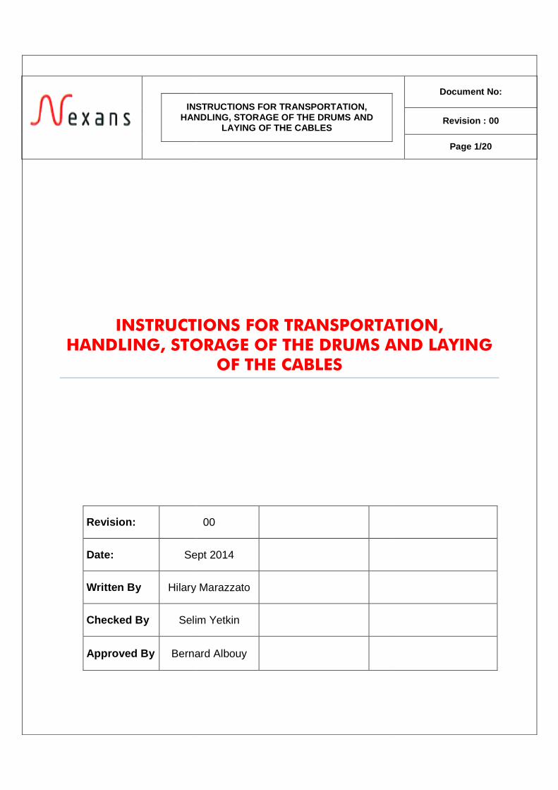
Drum flanges are marked to provide vital information to assist with the handling of the drums and the
installation of the cable. This information includes drum weight, a mark on the flange indicating the end
of the cable, and an arrow indicating the direction the drum is to be rolled during rolling or
transportation.
The rolling of the drum in the direction of the arrow ensures that there is no tendency for the cable to
loosen its wind on the drum. It should be noted that when pulling the cable off the drum and installing
the cable, the arrow will point in the opposite
Drum Handling
The movement of cable drums by motorised forklift truck is the preferred method. Most drums of cable
are within a weight range that permits their movement by this method.
In general, the forklift truck method of drum handling is only applicable where a hard and level ground
surface is available. This is required in the intended storage area. In this case a fork
about 12 tonnes will be required (maximum drum weight
ensure that the forklift truck tines are capable of traversing the width of the drum and provide support
to both flanges.
For the smaller drums, tines of 1200
1800 mm length. For the larger drums
cable, it will be necessary to have
supported by both drum flanges.
Some drums may be of sufficient length and weight to require cranes to load and unload from transport
vehicles. In this case, it will be necessary to ensure that a spreader bar of sufficient length is used to
ensure the lifting chains do not compr
The rolling of the drum in the direction of the arrow ensures that there is no tendency for the cable to
loosen its wind on the drum. It should be noted that when pulling the cable off the drum and installing
the cable, the arrow will point in the opposite direction to the rotation of the drum.
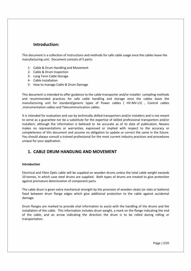
The movement of cable drums by motorised forklift truck is the preferred method. Most drums of cable
are within a weight range that permits their movement by this method.
forklift truck method of drum handling is only applicable where a hard and level ground
surface is available. This is required in the intended storage area. In this case a fork
about 12 tonnes will be required (maximum drum weight plus contingency). It is also necessary to
ensure that the forklift truck tines are capable of traversing the width of the drum and provide support
For the smaller drums, tines of 1200 mm length will be satisfactory. The larger drums wil
mm length. For the larger drums, for example containing 33 kV or 132 kV cables
, it will be necessary to have tines at least 2500 mm so that the cable drums are adequately
supported by both drum flanges.
Some drums may be of sufficient length and weight to require cranes to load and unload from transport
vehicles. In this case, it will be necessary to ensure that a spreader bar of sufficient length is used to
ensure the lifting chains do not compress the drum flanges.
Page | 3/20
The rolling of the drum in the direction of the arrow ensures that there is no tendency for the cable to
loosen its wind on the drum. It should be noted that when pulling the cable off the drum and installing
direction to the rotation of the drum.
The movement of cable drums by motorised forklift truck is the preferred method. Most drums of cable
forklift truck method of drum handling is only applicable where a hard and level ground
surface is available. This is required in the intended storage area. In this case a forklift capable of lifting
plus contingency). It is also necessary to
ensure that the forklift truck tines are capable of traversing the width of the drum and provide support
mm length will be satisfactory. The larger drums will require tines of
kV cables or long lengths of
tines at least 2500 mm so that the cable drums are adequately
Some drums may be of sufficient length and weight to require cranes to load and unload from transport
vehicles. In this case, it will be necessary to ensure that a spreader bar of sufficient length is used to
During transportation, cable drums must be securely restrained to prevent their movement and the
possibility of a serious mishap in which the cable could be damaged beyond repair.
When forklift or crane is not available, a makeshift ramp with approximate inclination of 1:4 should be
constructed. The cable drum should then be rolled over this ramp by means of ropes or winches.
Additionally, a sand bed at the foot of the ramp can be b
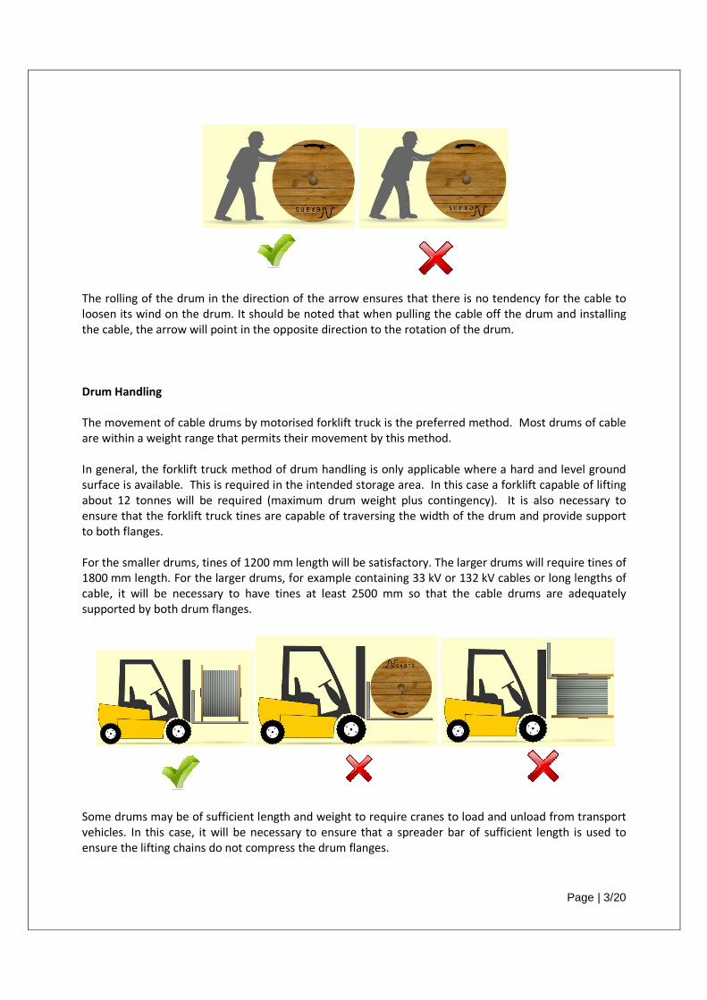
During transportation, cable drums must be securely restrained to prevent their movement and the
possibility of a serious mishap in which the cable could be damaged beyond repair.
When forklift or crane is not available, a makeshift ramp with approximate inclination of 1:4 should be
constructed. The cable drum should then be rolled over this ramp by means of ropes or winches.
Additionally, a sand bed at the foot of the ramp can be build to brake the rolling cable drum.
Page | 4/20
During transportation, cable drums must be securely restrained to prevent their movement and the
possibility of a serious mishap in which the cable could be damaged beyond repair.
When forklift or crane is not available, a makeshift ramp with approximate inclination of 1:4 should be
constructed. The cable drum should then be rolled over this ramp by means of ropes or winches.
uild to brake the rolling cable drum.
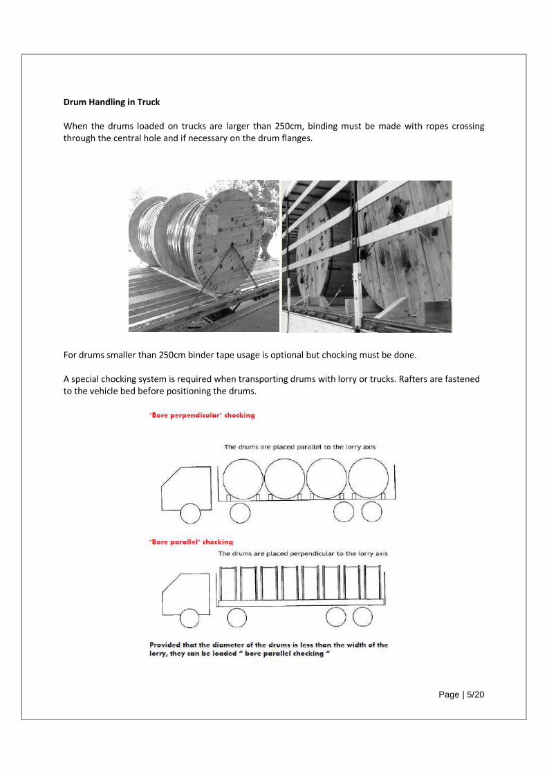
Drum Handling in Truck
When the drums loaded on trucks are larger than 250cm, binding must be made with ropes crossing
through the central hole and if necessary on the drum flanges.
For drums smaller than 250cm b
A special chocking system is required when transporting drums with lorry or trucks. Rafters are fastened
to the vehicle bed before positioning the drums.
loaded on trucks are larger than 250cm, binding must be made with ropes crossing
through the central hole and if necessary on the drum flanges.
binder tape usage is optional but chocking must b
A special chocking system is required when transporting drums with lorry or trucks. Rafters are fastened
to the vehicle bed before positioning the drums.
Page | 5/20
loaded on trucks are larger than 250cm, binding must be made with ropes crossing
be done.
A special chocking system is required when transporting drums with lorry or trucks. Rafters are fastened
Page | 6/20
2. DRUM AND CABLE INSPECTION Inspection Cable and drum should be inspected when received at the storage area.
Cable and drum should also be inspected before removal from the storage area.
Both wooden and steel cable drums should be inspected to ensure that the drum cleats (or slats or
battens) are not damaged.
If any damage has occurred in transit the cleats should be carefully removed to verify if any damage has
occurred to the cable. Normally the outer layer of cable on the drum has adequate space between it and
the inside of the drum cleats to prevent cable damage.
Additionally, inspection must include an assessment of the state of the drum due to transport vibration
and movement, weathering or environmental damage.
In changeable dry and wet weather, or consistently dry and hot weather (near or above 30oC), the
wooden section of the drum shrinks and the whole drum could become unstable and cause damage to
the cable when the drum is moved.
Therefore, the transverse bolts must be tightened with a torque wrench before the drums are moved
otherwise the drums could collapse during this operation. To ensure they are “tight” these bolts must
also be re-tightened during cable installation. The force (torque) shall be as follows:
• Drum size 700–1400 mm = force 80 Nm
• Drum size 1600–2200 mm = force 100 Nm
• Drum size 2500–2800 mm = force 120 Nm
The corrective action is to identify the 4 (or more) bolts extending from one flange to the other with
hexagonal nuts at each end. These nuts must be tightened before any unstable drum is moved.
The design of wooden drums for heavy power cable includes a metal spindle assembly to provide added
strength at the spindle hole. So, where fitted, the 4 (or more) bolts holding the steel plate at the spindle
hole are to be tightened or the drum will not turn smoothly on the shaft or spindles during cable
installation.
This procedure is to be adhered to in all installation projects before wooden drums are handled since the
effects of vibration, movement, the climate and duration of exposure to the environment can be
extensive.
Note that timbers of the drum flanges and barrels that have shrunk are likely to have loose nails as well
as the bolts, but loose nails are harder to correct. It will be necessary to apply caution and vigilance
during the cable unwinding to identify and reduce the damage to the cable produced by the loose nails.
Page | 7/20
If the cable ends are accessible, it is possible to inspect the presence and condition of the end caps. The
end cap is designed to prevent the ingress of moisture into the end of the cable. Any damage, holes or
cracks, in the end cap must be identified and the end cap replaced so to avoid any moisture or water
from entering the cable either due to further storage time or during installation.
If the end cap is absent, although the cable ends may have been sealed by a mastic or adhesive applied
on the cable end by the supplier, but if no end sealing is seen, a heat shrink cap should be applied
ensuring a tight seal to the cable outer layer.
It is also implied that, if the end cap or sealing is absent from the outer end of the cable (the end from
which the cable would normally be pulled), then the cable end must be examined and assessed.
The following is recommended, so if the cap or sealing has been absent for a long time (more than one
month); or the cable end faces up toward the sky; or the end cap has been absent during periods of rain;
or any form of cable end deterioration / ageing / swelling / or soiling is observed, then the cable end
should be cut back 300 mm and re-examined for presence of moisture and cut back further when
moisture is found, and a new end cap must be applied to the cable end, ensuring a tight seal to the cable
outer layer.
Warning
When any damage to the drum cleats (or slats or battens), or slackening of the cable layers has occurred,
or drums moved when unstable, then cable damage is possible and it is necessary to contact the nearest
Nexans representative to assess the situation and advise of an appropriate solution.
3. LONG TERM CABLE STORAGE
(more than 3 or 4 months) The instructions below are directed to assist in the case of any of the following:
a) Drums and the timber used in drums deteriorates with time and weather
b) Cable end caps deteriorate with time and weather
c) Exposed cable surfaces can deteriorate or colours fade
d) Cable can be damaged by the environment
e) Cable may be damaged during movements or transport
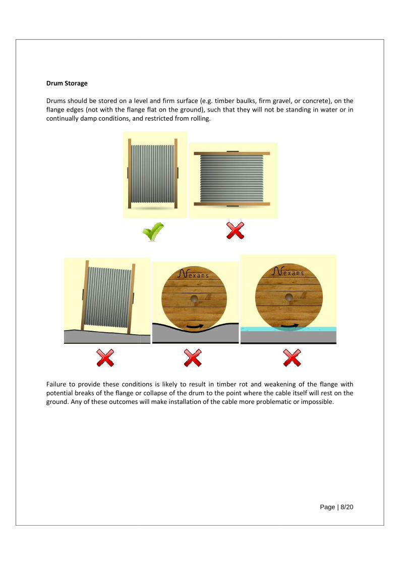
Drum Storage
Drums should be stored on a level and firm surface (e.g. timber baulks,
flange edges (not with the flange flat on the ground), such that they will not be standing in water or in
continually damp conditions, and restricted
Failure to provide these conditions is likely to result in timber rot and weakening of the flange with
potential breaks of the flange or collapse of the drum to the point where the cable itself will rest on the
ground. Any of these outcomes will make installation of the cable more problematic or impossible.
Drums should be stored on a level and firm surface (e.g. timber baulks, firm gravel, or concrete), on the
flange edges (not with the flange flat on the ground), such that they will not be standing in water or in
continually damp conditions, and restricted from rolling.
Failure to provide these conditions is likely to result in timber rot and weakening of the flange with
potential breaks of the flange or collapse of the drum to the point where the cable itself will rest on the
Any of these outcomes will make installation of the cable more problematic or impossible.
Page | 8/20
gravel, or concrete), on the
flange edges (not with the flange flat on the ground), such that they will not be standing in water or in
Failure to provide these conditions is likely to result in timber rot and weakening of the flange with
potential breaks of the flange or collapse of the drum to the point where the cable itself will rest on the
Any of these outcomes will make installation of the cable more problematic or impossible.
Page | 9/20
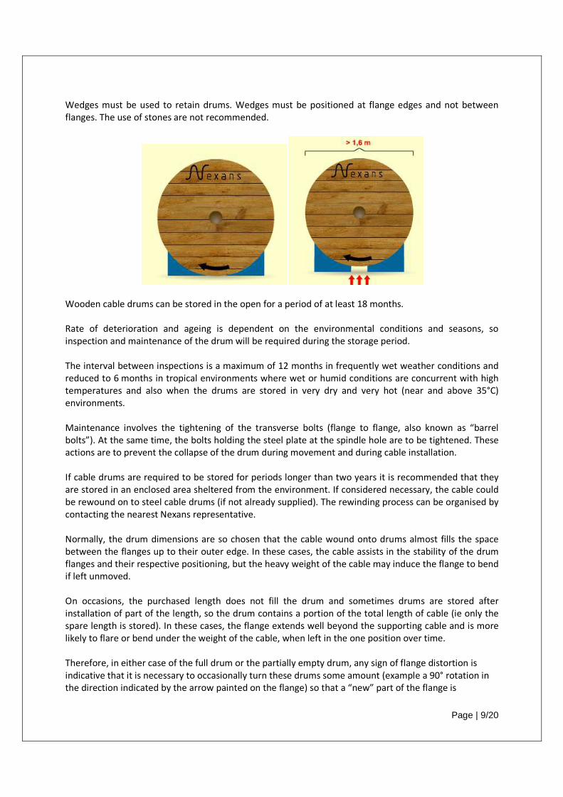
Wedges must be used to retain drums. Wedges must be positioned at flange edges and not between
flanges. The use of stones are not recommended.
Wooden cable drums can be stored in the open for a period of at least 18 months.
Rate of deterioration and ageing is dependent on the environmental conditions and seasons, so
inspection and maintenance of the drum will be required during the storage period.
The interval between inspections is a maximum of 12 months in frequently wet weather conditions and
reduced to 6 months in tropical environments where wet or humid conditions are concurrent with high
temperatures and also when the drums are stored in very dry and very hot (near and above 35°C)
environments.
Maintenance involves the tightening of the transverse bolts (flange to flange, also known as “barrel
bolts”). At the same time, the bolts holding the steel plate at the spindle hole are to be tightened. These
actions are to prevent the collapse of the drum during movement and during cable installation.
If cable drums are required to be stored for periods longer than two years it is recommended that they
are stored in an enclosed area sheltered from the environment. If considered necessary, the cable could
be rewound on to steel cable drums (if not already supplied). The rewinding process can be organised by
contacting the nearest Nexans representative.
Normally, the drum dimensions are so chosen that the cable wound onto drums almost fills the space
between the flanges up to their outer edge. In these cases, the cable assists in the stability of the drum
flanges and their respective positioning, but the heavy weight of the cable may induce the flange to bend
if left unmoved.
On occasions, the purchased length does not fill the drum and sometimes drums are stored after
installation of part of the length, so the drum contains a portion of the total length of cable (ie only the
spare length is stored). In these cases, the flange extends well beyond the supporting cable and is more
likely to flare or bend under the weight of the cable, when left in the one position over time.
Therefore, in either case of the full drum or the partially empty drum, any sign of flange distortion is
indicative that it is necessary to occasionally turn these drums some amount (example a 90° rotation in
the direction indicated by the arrow painted on the flange) so that a “new” part of the flange is
Page | 10/20
employed to support the cable weight. Failure to do this could result in a flange distortion that will make
it difficult to wind the cable off the drum and may result in damage to the cable.
Arresting or slowing the rate of deterioration for any drum, but particularly for those drums most
affected, can only be done by storage in a covered dry area.
Cable Storage
Cables are supplied with end cap sealing to prevent ingress of moisture or water. Cable drums should be
handled such that damage to the cable sheath or to sealing caps does not occur as this would
subsequently permit the ingress of moisture.
If the cable is used progressively (partial length is cut off and used) the exposed end must be
immediately sealed with a new end cap. Heat shrinkable end caps are recommended for this purpose
for installation as follows:
The cable end to be sealed must be cut at right angles and flat so that the cores do not
protrude from the sheath. To fit the end cap, position the cable end so that it is facing
vertically upwards.
Some hard plastic sheathing materials are quite smooth and slippery. These materials
may not adhere to the end cap and may not adhere even if mastic lined end caps are
used.
To enable adhesion to take place, such sheath materials must be abraded with coarse
sand paper before shrinking the end cap over the cable surface.
Place the end cap over the cable end and gently apply heat using a propane flame. Heat
should be applied evenly over the whole surface of the end cap, by smooth movements
of the flame (Only a small flame is necessary), but starting at the very end of the cable
and shrinking the cap sleeve away from the cable end.
Allow the cable end to cool and then check that the end cap has firmly gripped the cable
end and that a satisfactory seal has been achieved. Electricians' PVC tape is then
wrapped around the junction of the end cap and the cable sheath to reinforce the seal.
Cables with coloured outer sheaths should not be stored in direct sunlight to prevent fading of the
colour. Cables should be protected against direct sun light with suitable protection package such as
black plastic sheeting, lagging etc…
4. CABLE INSTALLATION Preparation for Cable Installation
Page | 11/20
Route preparation
The cable route needs to be prepared and inspected to ensure a proper installation can take place
without obstructions, protrusions, or debris in the way of the cable during a pull.
Cable ducting, if used, should also be checked to ensure they are clear and will not cause a jamming or
scraping of the cable sheath. In the case of very long duct runs, they may only be able to be checked
using special camera systems to verify the integrity of ducts, duct joins are not misaligned, and the ducts
are clean.
Drum and cable preparation
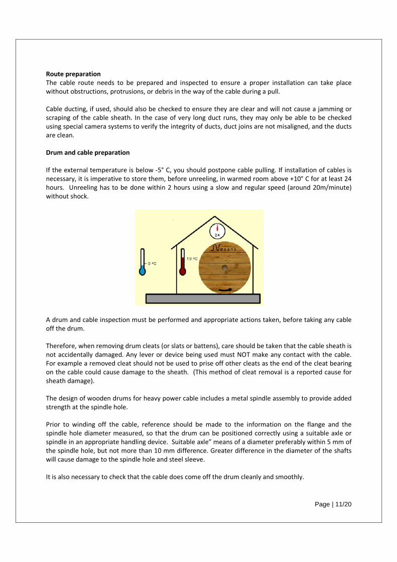
If the external temperature is below -5° C, you should postpone cable pulling. If installation of cables is
necessary, it is imperative to store them, before unreeling, in warmed room above +10° C for at least 24
hours. Unreeling has to be done within 2 hours using a slow and regular speed (around 20m/minute)
without shock.
A drum and cable inspection must be performed and appropriate actions taken, before taking any cable
off the drum.
Therefore, when removing drum cleats (or slats or battens), care should be taken that the cable sheath is
not accidentally damaged. Any lever or device being used must NOT make any contact with the cable.
For example a removed cleat should not be used to prise off other cleats as the end of the cleat bearing
on the cable could cause damage to the sheath. (This method of cleat removal is a reported cause for
sheath damage).
The design of wooden drums for heavy power cable includes a metal spindle assembly to provide added
strength at the spindle hole.
Prior to winding off the cable, reference should be made to the information on the flange and the
spindle hole diameter measured, so that the drum can be positioned correctly using a suitable axle or
spindle in an appropriate handling device. Suitable axle” means of a diameter preferably within 5 mm of
the spindle hole, but not more than 10 mm difference. Greater difference in the diameter of the shafts
will cause damage to the spindle hole and steel sleeve.
It is also necessary to check that the cable does come off the drum cleanly and smoothly.

Page | 12/20
It has been found that some cables with sheath materials that are affected by warmer ambient
temperatures (near or above 30°C, which means that actual cable surface temperature will be higher
than ambient temperature) or that are affected by the tension with which they are wound onto the
drum, may tend to exhibit some adhesion between the layers and turns of the cable. This adhesion, if
strong enough, may cause the cable to resist the unwinding and interfere with the installation. Remedial
action is to ensure that the turns are pulled off by hand or equipment, to ensure a smooth installation
pull.
Rotation of drum and drum brake
It should be noted that when pulling the cable off the drum, the arrow (painted on the flange of the
drum) will point in the opposite direction to the rotation of the drum. This is an expected practice.
A brake or other means of preventing unnecessary rotation of the drum is required. The lack of a brake
will result in extra rotation of the drum and surplus cable being forced off the drum. This presents a
safety risk for any adjacent operators and is likely to cause unacceptable damage to the cable.
The aim is to have the drum rotating only when cable is intentionally being pulled off. Excessive braking
is not necessary and may cause cable damage or make the pull unnecessarily difficult or induce too much
tension in the cable.
Pulling strength based on conductor types should be as follows:
• 5 daN/mm² of cross section for copper conductors
• 3 daN/mm² of cross section for aluminium conductors
During unreeling, drum rotational velocity and cable pulling velocity should be even, and should not
exceed 20 metre/minute.
Cable end caps and pulling eyes
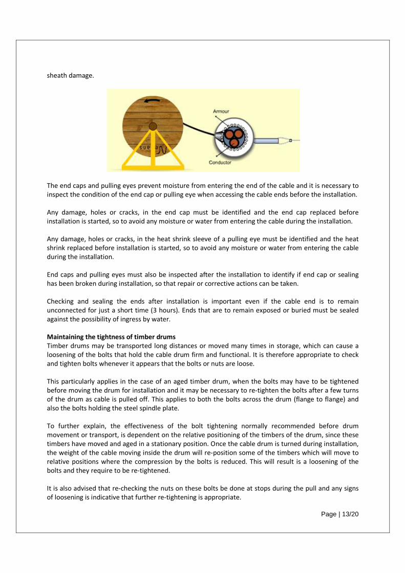
Cable ends will be protected by end caps or by pulling eyes. For longer lengths of cable (perhaps over
800 m) or for large conductor sizes (over 630 mm2), Nexans recommends the use of pulling eyes fixed to
the main conductors of the cable. Pulling long and heavy cables by pulling socks can lead to cable or
Page | 13/20
sheath damage.
The end caps and pulling eyes prevent moisture from entering the end of the cable and it is necessary to
inspect the condition of the end cap or pulling eye when accessing the cable ends before the installation.
Any damage, holes or cracks, in the end cap must be identified and the end cap replaced before
installation is started, so to avoid any moisture or water from entering the cable during the installation.
Any damage, holes or cracks, in the heat shrink sleeve of a pulling eye must be identified and the heat
shrink replaced before installation is started, so to avoid any moisture or water from entering the cable
during the installation.
End caps and pulling eyes must also be inspected after the installation to identify if end cap or sealing
has been broken during installation, so that repair or corrective actions can be taken.
Checking and sealing the ends after installation is important even if the cable end is to remain
unconnected for just a short time (3 hours). Ends that are to remain exposed or buried must be sealed
against the possibility of ingress by water.
Maintaining the tightness of timber drums
Timber drums may be transported long distances or moved many times in storage, which can cause a
loosening of the bolts that hold the cable drum firm and functional. It is therefore appropriate to check
and tighten bolts whenever it appears that the bolts or nuts are loose.
This particularly applies in the case of an aged timber drum, when the bolts may have to be tightened
before moving the drum for installation and it may be necessary to re-tighten the bolts after a few turns
of the drum as cable is pulled off. This applies to both the bolts across the drum (flange to flange) and
also the bolts holding the steel spindle plate.
To further explain, the effectiveness of the bolt tightening normally recommended before drum
movement or transport, is dependent on the relative positioning of the timbers of the drum, since these
timbers have moved and aged in a stationary position. Once the cable drum is turned during installation,
the weight of the cable moving inside the drum will re-position some of the timbers which will move to
relative positions where the compression by the bolts is reduced. This will result is a loosening of the
bolts and they require to be re-tightened.
It is also advised that re-checking the nuts on these bolts be done at stops during the pull and any signs
of loosening is indicative that further re-tightening is appropriate.
Page | 14/20
One effect of loose barrel bolts is that the tension on the cable during installation may be sufficient for
the cable end being pulled to force its way between other cable turns on the drum or between cable and
the drum flange. Trying to pry that embedded cable out can become difficult and may result in damage
to the cable.
Note that timbers of the drum flanges and barrels that have shrunk are also likely to have loose nails as
well as the bolts, but loose nails are harder to correct. It will be necessary to apply caution and vigilance
during the cable unwinding to identify and reduce the damage to the cable produced by the loose nails.
Loose nails in the flange can be pulled tight from the outside surface and clinched / bent hard against the
flange so they no longer will protrude on the inside of the drum.
Cable Make or Cable Creepage
During installation, it is expected
direction of the drum. It occurs less, or not at all, with steel drums and is normally a small extension with
timber drums. This extension is sometimes called “Cable
The inside end of the cable has a tendency to creep through the hole in the flange when the drum is
revolved in the opposite direction to that originally employed when winding the cable onto it. This
tendency cannot be prevented. The amount of creepage depends
drum, the size of the cable and the number of times the drum is revolved. The accumulated slack due to
unwinding long lengths of cable may amount to several
timber drums bolts have loosened or the timber has aged and shrinkage has taken place.
Cable-Make or Cable Creepage
bottom rather than the top of the drum and so the reeling is in the same direction of the arrow
on the flange of the drum. In this case, it may occur that the cable inner end, intentionally left out for
testing, will in fact withdraw into the drum and will be “lost” unless it is fixed firmly to the drum flange. If
the end is allowed to move inside the drum, it is possible that the friction and tight space will exert
pressure on any cable end cap and cause it to be pulled off.
Note that to enable a pull to be moved from a top to a bottom feed, it is necessary to stop the pulling
process, relieve the cable tension, and lift the cable drum off the stand, rotate the drum 180
vertical axis, and re-position in the stand, while ensuring that the cable end being pulled is not damaged.
Not impossible, but care and a risk assessment is requ
To avoid creepage and sinuous shape on the barrel of the drum during paying off, the
cable on the drum flange should be free, not fixed to the drum.
Fixed Cable End –Creepage occurs
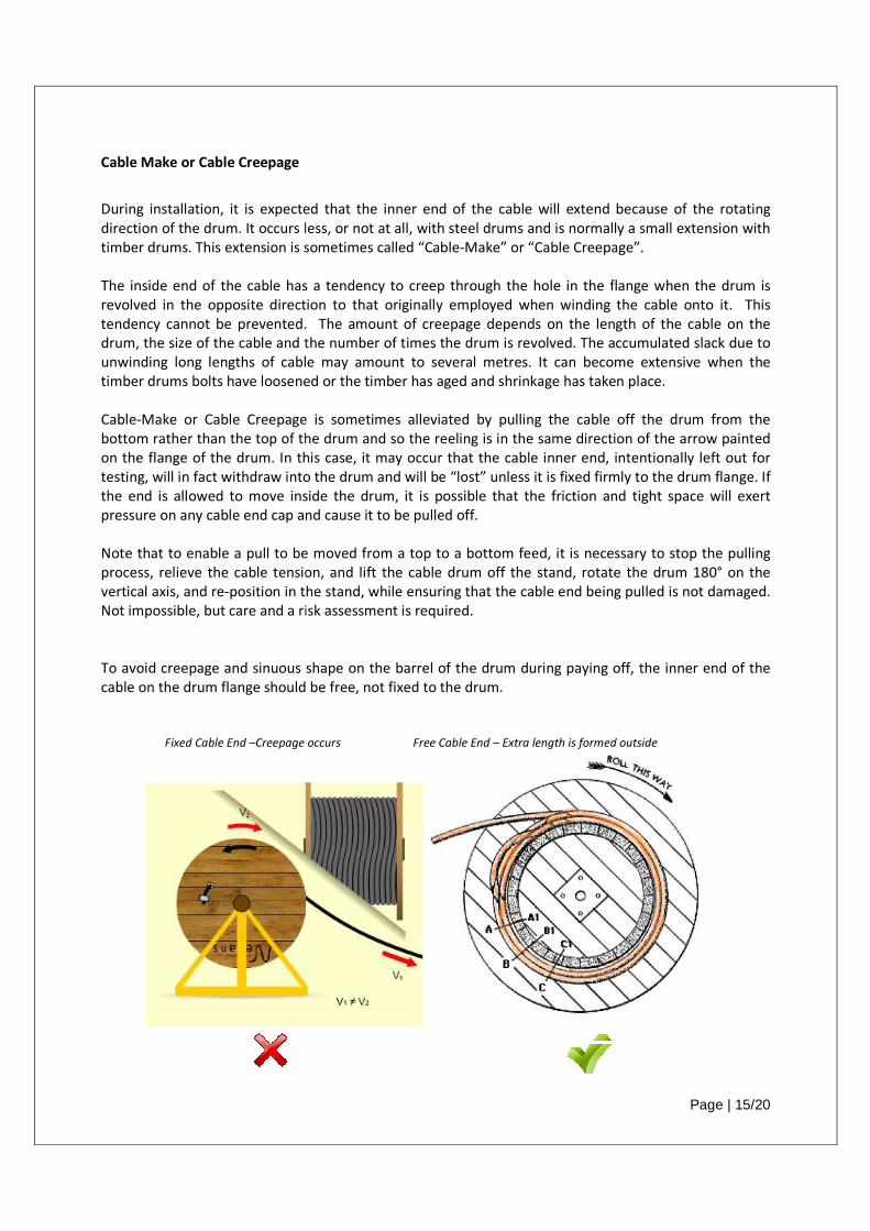
installation, it is expected that the inner end of the cable will extend because of the rotating
direction of the drum. It occurs less, or not at all, with steel drums and is normally a small extension with
timber drums. This extension is sometimes called “Cable-Make” or “Cable Creepage”
ide end of the cable has a tendency to creep through the hole in the flange when the drum is
revolved in the opposite direction to that originally employed when winding the cable onto it. This
tendency cannot be prevented. The amount of creepage depends on the length of the cable on the
drum, the size of the cable and the number of times the drum is revolved. The accumulated slack due to
unwinding long lengths of cable may amount to several metres. It can become extensive when the
loosened or the timber has aged and shrinkage has taken place.
or Cable Creepage is sometimes alleviated by pulling the cable off the drum from the
bottom rather than the top of the drum and so the reeling is in the same direction of the arrow
on the flange of the drum. In this case, it may occur that the cable inner end, intentionally left out for
testing, will in fact withdraw into the drum and will be “lost” unless it is fixed firmly to the drum flange. If
nside the drum, it is possible that the friction and tight space will exert
pressure on any cable end cap and cause it to be pulled off.
Note that to enable a pull to be moved from a top to a bottom feed, it is necessary to stop the pulling
relieve the cable tension, and lift the cable drum off the stand, rotate the drum 180
position in the stand, while ensuring that the cable end being pulled is not damaged.
Not impossible, but care and a risk assessment is required.
To avoid creepage and sinuous shape on the barrel of the drum during paying off, the
cable on the drum flange should be free, not fixed to the drum.
Creepage occurs Free Cable End – Extra length is formed outside
Page | 15/20
r end of the cable will extend because of the rotating
direction of the drum. It occurs less, or not at all, with steel drums and is normally a small extension with
or “Cable Creepage”.
ide end of the cable has a tendency to creep through the hole in the flange when the drum is
revolved in the opposite direction to that originally employed when winding the cable onto it. This
on the length of the cable on the
drum, the size of the cable and the number of times the drum is revolved. The accumulated slack due to
It can become extensive when the
loosened or the timber has aged and shrinkage has taken place.
is sometimes alleviated by pulling the cable off the drum from the
bottom rather than the top of the drum and so the reeling is in the same direction of the arrow painted
on the flange of the drum. In this case, it may occur that the cable inner end, intentionally left out for
testing, will in fact withdraw into the drum and will be “lost” unless it is fixed firmly to the drum flange. If
nside the drum, it is possible that the friction and tight space will exert
Note that to enable a pull to be moved from a top to a bottom feed, it is necessary to stop the pulling
relieve the cable tension, and lift the cable drum off the stand, rotate the drum 180° on the
position in the stand, while ensuring that the cable end being pulled is not damaged.
To avoid creepage and sinuous shape on the barrel of the drum during paying off, the inner end of the
Extra length is formed outside
Page | 16/20
Cable Installation
Installation of the cable must be performed within these guidelines:
a) Maximum pulling tension.
The cable must not be pulled with a tension above the maximum pulling tension.
It is recommended that a load cell is in-line with the cable to measure the tension. Calculations
should be done before the pull to ensure an appropriate number of cable-pullers and cable-
pushers are used to keep cable tension below the maximum value and the load cell is monitored
to ensure the maximum tension is not exceeded. Many installers will have recording devices so
that the digital output from the load cell is stored and proof can be presented that each cable
pull was performed below maximum tension.
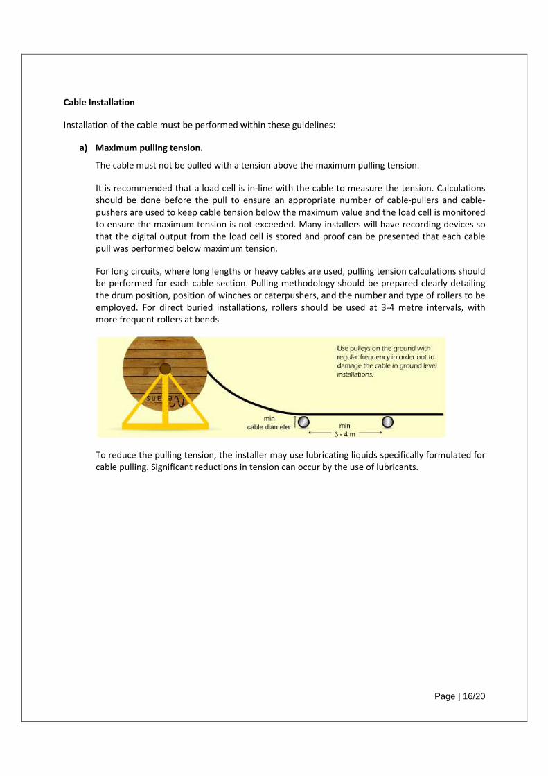
For long circuits, where long lengths or heavy cables are used, pulling tension calculations should
be performed for each cable section. Pulling methodology should be prepared clearly detailing
the drum position, position of winches or caterpushers, and the number and type of rollers to be
employed. For direct buried installations, rollers should be used at 3-4 metre intervals, with
more frequent rollers at bends
To reduce the pulling tension, the installer may use lubricating liquids specifically formulated for
cable pulling. Significant reductions in tension can occur by the use of lubricants.
Page | 17/20
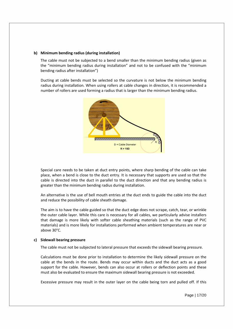
b) Minimum bending radius (during installation)
The cable must not be subjected to a bend smaller than the minimum bending radius (given as
the “minimum bending radius during installation” and not to be confused with the “minimum
bending radius after installation”)
Ducting at cable bends must be selected so the curvature is not below the minimum bending
radius during installation. When using rollers at cable changes in direction, it is recommended a
number of rollers are used forming a radius that is larger than the minimum bending radius.
Special care needs to be taken at duct entry points, where sharp bending of the cable can take
place, when a bend is close to the duct entry. It is necessary that supports are used so that the
cable is directed into the duct in parallel to the duct direction and that any bending radius is
greater than the minimum bending radius during installation.
An alternative is the use of bell mouth entries at the duct ends to guide the cable into the duct
and reduce the possibility of cable sheath damage.
The aim is to have the cable guided so that the duct edge does not scrape, catch, tear, or wrinkle
the outer cable layer. While this care is necessary for all cables, we particularly advise installers
that damage is more likely with softer cable sheathing materials (such as the range of PVC
materials) and is more likely for installations performed when ambient temperatures are near or
above 30°C.
c) Sidewall bearing pressure
The cable must not be subjected to lateral pressure that exceeds the sidewall bearing pressure.
Calculations must be done prior to installation to determine the likely sidewall pressure on the
cable at the bends in the route. Bends may occur within ducts and the duct acts as a good
support for the cable. However, bends can also occur at rollers or deflection points and these
must also be evaluated to ensure the maximum sidewall bearing pressure is not exceeded.
Excessive pressure may result in the outer layer on the cable being torn and pulled off. If this
Page | 18/20
takes place, it is a common effect that the tear will continue during the cable pull and the torn
sheath will accumulate at one point within the bend and create an increase in cable pulling
tension.
d) Deformation of the sheath
A combination or action of any of the above three items, even without exceeding any of the
manufacturers recommendations, can result in the elongation of outer layer of the cable and
form a “rucking” or “corrugation” of the cable sheath during installation.
Deformation of the sheath during installation is known to occur when the sheath material is
softened by elevated temperatures, such as the range of PVC sheathing materials, particularly
when the cable is installed in warmer ambient temperatures (near and above 30°C). Note that
actual cable surface temperature can be higher than ambient temperature.
It is also known to occur when the outer layer is thinner than a full sheath, such as may occur
when installing a Nylon covered cable, which is covered by a thin Sacrificial Sheath.
Such deformation should be monitored to avoid an escalation to very severe puckering, which
could induce the tearing of the sheath. Rucking, corrugation, and puckering can be reduced by
the use of lubricating substances which will reduce the friction experienced at turns or bends on
fixed deflectors and on rollers and even on long straight sections.
Note that longer runs and heavier cables will experience this deformation more often.
Corrective action includes the pausing of the installation pull and the easing of tension and
pulling the affected cable length past the bend or roller or friction point that is causing the effect.
Once the affected area is moved along, there is often a re-settling of the elongated sheath and
the effect is reduced. Stopping and allowing the cable to cool, will tend to set the corrugations in
place and they will not easily be removed.
Where this deformation takes place, there is a small reduction of the thickness where the
material is stretched, but such deformation as a whole is considered to be of minor
consequence.
Usually, no repair or corrective action is required on the cable itself.
Repair is only necessary when there is a breaking or tearing of the sheath.
e) Thermal backfill
When special thermal backfill is required, it is important that the installer to be fully informed of
the arrangement planned. There will be a defined minimum thickness of backfill below the cable
and a minimum thickness above the cable, as well as a width of trench that must be filled with
backfill material.
In order for the cables to avoid overheating during operation, it is important that the minimum
thicknesses of backfill are maintained along the complete route of the cable.
Also, the backfill material must not be mixed with native soil or other available materials as they
are not likely to have the same thermal properties as the backfill materials selected.
Page | 19/20
Failure to comply with minimum thickness or failure to ensure that only clean backfill material is
used will result in the cable overheating during operation.
A cable failure is not likely in the short term, but eventually the excessive heat will cause a
breakdown of the cable insulation. It is likely that a cable repair will be expensive and difficult to
perform and the loss of supply could incur very high costs for the operation of the plant.
f) Free movement of the drum
It is also necessary to check that the cable does come off the drum cleanly and smoothly.
Sufficient tension is required to ensure the cable comes off the drum and moves in the direction
of the pull without a bend that is smaller than the bending radius of the cable.
Obstructions, protrusions, and equipment frames should not interfere with the path of the cable
and the installer must ensure the cable is not damaged.
Summary
The installer must take precautions to ensure the cable is installed correctly and without damage. The
above specific points must be observed, but additional observation and care may be needed by the
installer to ensure a successful installation.
5. HOW TO MANAGE DRUM AND CABLE DAMAGE
Timber drums do deteriorate over time when exposed to the weather and the level of deterioration is
dependent on the variety and type of weather to which the drum is exposed.
Temperate or colder environments are the most kind to the ageing process, but wetness can induce rot
in the timber and wetness concurrent high temperatures (as may be found in tropical areas) will
accelerate the rotting process. The most obvious point of fastest deterioration is the contact point of the
timber drum to the ground, so it is essential for the drums to be stored on a firm gravel surface or on
concrete and that the drum is not allowed to rest with the flange in water.
Dry and hot environments (near and above 35°C) will have the effect of drying out the timber and
inducing timber shrinkage. The metal components (bolts, shafts, and nails) that hold the timbers in place
will therefore need to be tightened to avoid a loose assembly of timber that will not tolerate the forces
of transport and unwinding of the cable during an installation.
With a drum that has aged or deteriorated, it is necessary that the transverse bolts (flange to flange, also
known as “barrel bolts”) are inspected and tightened and the bolts holding the steel plate at the spindle
hole are to be tightened. Inspection is required before lifting or moving the drum and also after a few
turns of the drum at installation and at intervals during the installation.
One effect of loose barrel bolts is that the tension on the cable during installation may be sufficient for
the cable end being pulled to force its way between other cable turns on the drum or between cable and
the drum flange. Trying to pry that embedded cable out can become difficult and may result in damage
to the cable.
Page | 20/20
It is also important that the shaft or spindles used to support the drum during unwinding or installation
of the cable are close to the size of the hole provided in the drum. Shafts or supports that are too small
will tend to gouge the spindle hole so that rotation of the drum becomes uneven, usually leading to
additional damage and greater gouging of the spindle hole which leads to greater difficulty in using the
drum and cable and could even escalate to a point that winding is no longer possible.
Should it be apparent that spindle hole damage continues to occur then a larger spindle hole needs to be
formed or a Nexans representative be contacted for assistance.
Looseness in the bolts around a spindle plate may induce similar problems. This is why these bolts also
need to be tightened.
Lubrication of the shaft or spindle is advised when the timbers around the spindle hole or around the
spindle plate are suspected of being weakened by ageing. The lubrication will relieve rotational forces on
the timbers and on the spindle plate bolts and the timbers they are bolted to.
It is more difficult to tighten loose nails and some nails that are under the cable will not be accessible.
Thus care is required to make observations and take corrective actions to avoid cable damage.
In those cases where damage is not avoidable then the following corrective actions are recommended:
a) In the case of the damage being sustained on the surface of the cable sheath and not
penetrating much of the thickness (say depth of damage less than 1.5 mm or 50% of the total
thickness, whichever is smallest) then no repair action is required.
b) Should it be desired to repair deeper damage or broken or torn or slit sheath, then a heat shrink
sleeve to cover all such damage is acceptable and most commonly used for such repairs.
In terms of cable longevity, for damage deeper than 1.5 mm or 50% of the sheath thickness, a heat
shrink sleeve over the damage restores the function of the sheath.
And should the cable sheath be torn or broken or slit, a heat shrink sleeve over this damage restores the
function of the sheath.