instruction manual – microchem 2 chlorine probes series...
TRANSCRIPT

- 1 - 210.6410.1
Instruction Manual – MicroChem®2 Chlorine Probes Series CL4000

210.6410.1 - 2 -
These instructions describe the installation, operation and maintenance of the subject equipment. Failure to strictly follow these instructions can lead to an equipment rupture that may cause significant property damage, severe personal injury and even death. If you do not understand these instructions, please call De Nora Water Technologies for clarification before commencing any work at +1 215-997-4000 and ask for a Field Service Manager. De Nora Water Technologies, Inc. reserves the rights to make engineering refinements that may not be described herein. It is the responsibility of the installer to contact De Nora Water Technologies, Inc. for information that cannot be answered specifically by these instructions.
Any customer request to alter or reduce the design safeguards incorporated into De Nora Water Technologies equipment is conditioned on the customer absolving De Nora Water Technologies from any consequences of such a decision.
De Nora Water Technologies has developed the recommended installation, operating and maintenance procedures with careful attention to safety. In addition to instruction/operating manuals, all instructions given on labels or attached tags should be followed. Regardless of these efforts, it is not possible to eliminate all hazards from the equipment or foresee every possible hazard that may occur. It is the responsibility of the installer to ensure that the recommended installation instructions are followed. It is the responsibility of the user to ensure that the recommended operating and maintenance instructions are followed. De Nora Water Technologies, Inc. cannot be responsible for deviations from the recommended instructions that may result in a hazardous or unsafe condition.
De Nora Water Technologies, Inc. cannot be responsible for the overall system design of which our equipment may be an integral part of or any unauthorized modifications to the equipment made by any party other that De Nora Water Technologies, Inc.
De Nora Water Technologies, Inc. takes all reasonable precautions in packaging the equipment to prevent shipping damage. Carefully inspect each item and report damages immediately to the shipping agent involved for equipment shipped “F.O.B. Colmar” or to De Nora Water Technologies for equipment shipped “F.O.B Jobsite”. Do not install damaged equipment.
De Nora Water Technologies, COLMAR OPERATIONS COLMAR, PENNSYLVANIA, USA ISO 9001: 2008 CERTIFIED

- 3 - 210.6410.1
TABLE OF CONTENTS
1 INTRODUCTION...........................................................................................................................4 1.1 General Description ..........................................................................................................4 1.2 Safety ...............................................................................................................................4
1.3 Chlorine Probes, Cables, Accessories and Consumables ...............................................5 1.4 Technical Data / Specifications.........................................................................................6
1.5 Principle of Operation .......................................................................................................7 2 INSTALLATION ............................................................................................................................8
2.1 General..............................................................................................................................8 2.2 Mounting Dimensions........................................................................................................8
2.3 Chlorine Probes...............................................................................................................10 2.4 Flow Cell Panel................................................................................................................11
2.5 Plumbing Connections ........................................................................................11 2.5.1 Drain ....................................................................................................................11 2.5.2 Sample Inlet.........................................................................................................11
2.6 Sample Flow Regulation..................................................................................................11 2.6.1 General................................................................................................................11 2.6.2 Sample flow adjustment ......................................................................................12
2.7 Probe Electrical Connections..........................................................................................15 2.7.1 Chlorine probes...................................................................................................15 2.7.2 Other probes .......................................................................................................17 2.7.3 Wire duct .............................................................................................................17
3 STARTUP .............................................................................................................................18 4 MAINTENANCE..........................................................................................................................19
4.1 Periodic Functional Check ..............................................................................................19 4.2 Electrode Maintenance ...................................................................................................19
4.2.1 Electrode Membrane...........................................................................................19 4.2.2 Cleaning the electrode surfaces .........................................................................19
4.3 Flow Cell Maintenance...................................................................................................19 5 TROUBLE SHOOTING PROCEDURE.......................................................................................20
FIGURES 1 Chlorine Probe ..............................................................................................................................4 2 Mounting Dimensions – Panel Assembly with MicroChem®2 ......................................................8 3 Mounting Dimensions – Panel Assembly with MicroChem, Remote ............................................9 4 Chlorine Probe Components.......................................................................................................13 5 Panel Arrangement .....................................................................................................................14 6 Probe Cable Connections ..........................................................................................................16

210.6410.1 - 4 -
1 INTRODUCTION
1.1 General Description This manual describes the general description, installation, operation and maintenance of the CL4000 Chlorine probes and accessories.
Chlorine is the most common chemical used in disinfection of municipal drinking water, cooling towers and many industrial applications.
A chlorine measuring system incorporating the CL4000 chlorine probes, connected to the MicroChem®2 transmitter, provides automatic measurement/control of chlorine dosage. The CL4000 chlorine probe measures free chlorine.
The transmitter is part of the MicroChem2 series, which is capable of supporting up to three of the following measurements in all possible combinations: Dissolved Oxygen, Chlorine Dioxide, Residual Chlorine, Bromine, Ozone, ORP, Temperature, pH, Iodine and Conductivity. For a description and instructions regarding the transmitter, see the MicroChem2 transmitter instruction manual.
The chlorine probes are 3 electrode amperometric cells covered with a permeable membrane. The probe exterior is manufactured from a durable PVC and stainless steel and has a diameter of 25mm (1 inch). The probes are engineered to fit a specially designed flow cell.
De Nora Water Technologies chlorine probes can be used without the need for pH compensation.
All the CL4000 probes are designed to run without the need for reagents. The probes have no moving parts and are designed to require minimal maintenance.
Figure 1 - Chlorine Probe
1.2 Safety The recommended operating procedures have been designed with careful attention to safety. De Nora Water Technologies has made formal safety reviews of the initial design and any subsequent changes. This procedure is followed for all new products and covers areas in addition to those included in applicable safety standards.
Observe the following safety precautions: a. Observe all safety warnings marked on the equipment. These warnings identify areas of
immediate hazard, which could result in personal injury, or loss of life.b. Do not use this equipment for any purpose other than described in this manual.c. Disconnect power prior to making any terminal connections within the enclosure.d. Use the recommended connection procedures described in Section 2 of this manual.
This equipment should only be installed by suitably qualified personnel.

- 5 - 210.6410.1
1.3 Chlorine Probes, Cables, Accessories and Consumables
Chlorine Probe 0-2 ppm, pH tolerable 4.0 - 9.5 (Note 1) 23183 Chlorine Probe 0-5 ppm, pH tolerable 4.0 - 9.5 (Note 1) 23184 Chlorine Probe 0-10 ppm, pH tolerable 4.0 - 9.5 (Note 1) 23185
4 Foot Cable (Note 2) 78-400112 Foot Cable (Note 2) 78-400240 Cable (Note 2) 78-4003Sample Tubing, 1/4” OD (25 ft) 17594 Sample Tube Fitting ¼ NPT x ¼ OD Tube 26098 Drain Tube , ¾” ID (ordered by the foot) R-886Flow Through Cell Remote Panel (Note 3) 26738 Flow Through Cell Remote Panel with PRV option (Note 4, 5) 26881 Y Strainer 80 mesh, Max Inlet 75 PSIG 22901 Pressure Reducing Valve Kit, 0-15 PSIG, Max Inlet 150 PSIG w/15 PSIG Gauge & Bracket (Note 5) 26735 Flow Switch (Note 6) 22896 Carbon Dechlorinating Filter (Note 7) 26903 Annual Maintenance Kit for: 23183, 23184, 23185, 01-4032 and 01-4033 Probes Includes: PN 77-4004 and PN 94-2136 10-400201-4034 and 01-4035 ProbesIncludes: PN 77-4004 and PN 94-2137 10-4003
M48 Membrane Cap to fit 23183, 23184, 23185, 01-4032, 01-4033, 01-4034 and 01-4035 Probes 77-4004G-Holder for 23183, 23184, 23185, 01-4032 and 01-4033 Probes 77-4017Electrolyte Solution (100ml) for 23183, 23184, 23185, 01-4032 and 01-4033 Probes (Note 8) 94-2136Electrolyte Solution (100ml) for 01-4034 and 01-4035 Probes (Note 8) 94-2137
Notes:
1. 23183, 23184, and 23185, probes with 3-electrode sensor for the measurement of free available chlorine.Temperature compensated (0 to 40°C). pH tolerable within the operating range 4 to 9.5.
2. Cable 78-4001, 78-4002 or 78-4003 must be used for probe to function properly.3. Used when sample inlet pressure is constant and between 2 – 15 psi.4. For use with fluctuating sample inlet pressure or inlet pressure up to 150 psi.5. PRV kit is included with Panel #26881, but may be added to Panel #26738 if necessary.6. Flow Switch: dry contact opens on loss of sample flow.7. Dechlorinating Filter provides a chlorine free sample stream, used for calibrating the MicroChem®2. (includes 2, #26098 tubing
fittings)8. 100 ml of electrolyte is enough for 15 electrolyte refittings.
210.6410.1 - 6 -
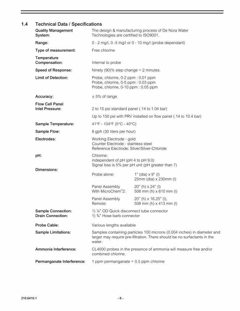
1.4 Technical Data / Specifications
Quality Management System:
Range:
Type of measurement:
Temperature Compensation:
Speed of Response:
Limit of Detection:
Accuracy:
Flow Cell Panel Inlet Pressure:
Sample Temperature:
Sample Flow:
Electrodes:
pH:
The design & manufacturing process of De Nora Water Technologies are certified to ISO9001.
0 - 2 mg/l, 0 -5 mg/l or 0 - 10 mg/l (probe dependant)
Free chlorine
Internal to probe
Ninety (90)% step change < 2 minutes.
Probe, chlorine, 0-2 ppm : 0.01 ppm Probe, chlorine, 0-5 ppm : 0.03 ppm Probe, chlorine, 0-10 ppm : 0.05 ppm
± 5% of range
2 to 15 psi standard panel (.14 to 1.04 bar)
Up to 150 psi with PRV installed on flow panel (.14 to 10.4 bar)
41°F - 104°F (5°C - 40°C)
8 gph (30 liters per hour)
Working Electrode - gold Counter Electrode - stainless steel Reference Electrode: Silver/Silver-Chloride
Chlorine:independent of pH (pH 4 to pH 9.0) Signal loss is 5% per pH unit (pH greater than 7)
Dimensions:Probe alone: 1” (dia) x 9” (l)
25mm (dia) x 230mm (l)
Panel Assembly 20” (h) x 24” (l) With MicroChem®2: 508 mm (h) x 610 mm (l)
Panel Assembly 20” (h) x 16.25” (l), Remote: 508 mm (h) x 413 mm (l)
Sample Connection: 1) ¼” OD Quick disconnect tube connectorDrain Connection: 1) ¾” Hose barb connector
Probe Cable: Various lengths available
Sample Limitations: Samples containing particles 100 microns (0.004 inches) in diameter and larger may require pre-filtration. There should be no surfactants in the water.
Ammonia Interference: CL4000 probes in the presence of ammonia will measure free and/or combined chlorine.
Permanganate Interference: 1 ppm permanganate = 0.5 ppm chlorine

- 7 - 210.6410.1
1.5 Principle of Operation The chlorine probes are amperometric cells covered with a permeable membrane. The probes are engineered to fit a specially designed flow cell.
A sample of liquid is delivered to the input (bottom) of the flow panel at an approximate rate of 500 ml/min.
The flow cell operates on a constant head principle. Incoming sample is regulated by a sample control valve. The sample control valve is adjusted such that a constant flow comes out of the overflow tube and into the drain. So long as excess sample is coming out of the overflow tube, the flow and pressure of the sample will be held constant in the flow cell.
The sample passes through the flowcell to the membrane on the tip of the probes membrane cap. Chlorine diffuses through the membrane and into the internal filling solution where a small DC current is generated between the stainless steel counter electrode and gold working electrode in direct linear proportion to the amount of residual present in the sample. A third reference electrode establishes a constant potential on the gold working electrode to provide an accurate and stable residual signal.
The signal is amplified and transmitted to the MicroChem®2 transmitter/controller via the sensor cable. The probe needs to be loop powered. This power is generated within the MicroChem2 and supplied to the probe in the same cable which transmits the residual signal.
All the CL4000 chlorine probes are designed to run without the need for reagents. The probes have no moving parts and are designed to require minimal maintenance.

210.6410.1 - 8 -
2 INSTALLATION
2.1 General Remove the instrument from its box and carefully inspect each item and report damages immediately. The box will include the chlorine probe (electrode shaft, top cap and membrane cap with G holder), electrolyte bottle and a sheet of blue abrasive paper.
The chlorine probes are designed for general duty indoor installation. Outdoor installation is possible if the instrument is shielded from dripping water and not mounted in direct sunlight. Ensure that the process and environmental conditions are within specified limits (see specification). Excessive heat and vibration will affect the sensors.
2.2 Mounting Dimensions
Reference Dimensional Drawing 210D1041
Figure 2 – Panel Assembly, MicroChem®2 Mounting Dimensions
INLET
OUTLET
SAMPLE
- 9 - 210.6410.1
OUTLET
SAMPLE
INLET
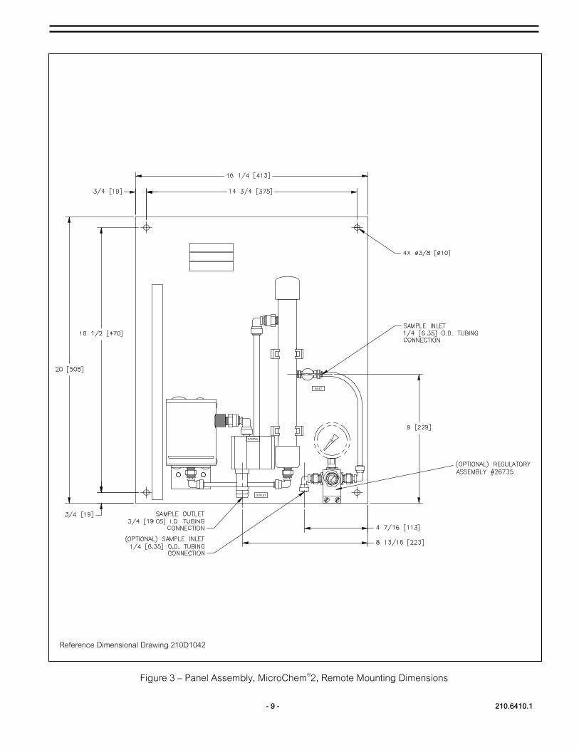
Reference Dimensional Drawing 210D1042
Figure 3 – Panel Assembly, MicroChem®2, Remote Mounting Dimensions

210.6410.1 - 10 -
Vent holeVent Seal
2.3 Chlorine Probes
Do not touch the electrode finger (see Figure 4) Do not touch the bottom of the membrane cap (see Figure 4)
CAUTION
To assemble the probes for use:
Fill the membrane cap to the top with electrode filling solution (note each electrode has a specially formulated filling solution which is unique to that sensor – see parts list for details). Tap the side of the membrane cap to remove any air bubbles that may have formed in the solution.
Reposition the vent seal, making sure that the vent hole is completely covered.
Fill up the G-holder with filling solution. Be careful that there are no bubbles.
Hold the electrode shaft upright and push the electrode finger carefully into the filled G-holder.
While holding the electrode shaft vertically with the G-holder in place, screw the filled membrane cap back on to the electrode shaft until tight to probe shoulder. Make sure not to press on the vent ring seal or cover the area of the vent hole with a finger when installing the membrane cap. Excess filling solution will escape from top or the vent in the membrane cap. Rinse off any filling solution that may have escaped during the installation with clean water.
When removing the membrane cap, move the vent seal away from the vent hole to allow air into the membrane cap. Not doing so may cause a vacuum to form and damage the membrane.

- 11 - 210.6410.1
Note: The G-holder is supplied and required for use with the chlorine probes and with the annual maintenance kits containing the M48 membrane cap. See parts list for details.
Note: When unscrewing the filled membrane cap from the electrode shaft, first remove the vent seal and ensure that the vent is not covered by a finger (air needs to be allowed through the vent hole to equalize the pressure).
Note: Make sure the membrane cap is tightly fastened to the electrode shaft ensuring that no gap remains between the electrode shaft and the membrane cap.
Note: It is best to wait 1 - 4 hours before the first calibration is performed. After one day, repeat the calibration. See the MicroChem®2 electronics manual for calibration instructions.
Note: Calibration must be made with a continuous flow of liquid at 500 mL/min at the flow panel inlet.
2.4 Flow Cell Panel The flow cell panel will accept one 25 mm chlorine probe and an additional 12 mm probe to be used to measure another parameter in a common sample stream. The flow cell is shipped with plugs inserted in the probe openings. Remove the plug(s) as required to install probe(s) into the cell. The Chlorine probe is inserted into the larger 25 mm opening. Push the probe through the o-ring retainer and press it down until it rests on the bottom of the cell. If additional (optional) 12 mm probe is to be installed, it should be inserted in the cell such that the probe tip is full immersed in the sample.
Note: Chlorine and Conductivity cannot be measured within the same flow cell.
2.5 Plumbing Connections (See Figure 5) 2.5.1 Drain
Ten feet of ¾” I.D. clear drain tubing has been supplied with the flow cell panel. Connect the drain tube to the ¾” hose barb on the bottom of the drain assembly and secure with the supplied hose clamp. Insert the opposite end of the drain tube into the local site drain system.
2.5.2 Sample Inlet Fifteen feet of 1/4” O.D. tubing has been supplied with the flow cell panel to connect the water supply to the panel. Cut the tube to length as necessary to fit the site installation needs. Push tubing into the sample inlet connection fitting. If it becomes necessary to release the tube from the fitting simply push on the fittings collar and pull back on the tubing. One ¼ “NPT fitting # 26098 is supplied to allow for tube connection to the site plumbing. Install the fitting in the site plumbing and push the sample tube into the fitting to complete the sample line connection.
2.6 Sample Flow Regulation 2.6.1 General
Maintaining constant flow and pressure to a chlorine measuring probe is essential for reliable operation. De Nora Water Technologies’ Flow Cell incorporates a constant head flow design to provide measurement stability.

210.6410.1 - 12 -
When water sample pressure is consistent and between 2 and 15 psi, the flow to the measuring cell can be controlled via the sample valve on the side of the overflow tube. For applications where the sample pressure is greater then 15 psi or variable, the optional PRV assembly # 26735 should be used.
2.6.2 Sample Flow Adjustment (See Figure 5) For flow cell panels that have the optional pressure regulator (3) installed set the regulator to 8psi via the adjustment screw on the front of the regulator.
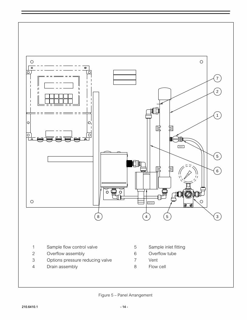
Sample flow is regulated by the valve (1) located on the right side of the overflow assembly (2). Once water is supplied to the panel, allow the overflow assembly and flow cell (8) to fill. Adjust the sample flow control valve such that you have a consistent flow coming out of the overflow tube (6) going into the drain (4). If water is noticed coming out of the vent hole (7) on the top left side of the overflow tube the flow must be reduced by closing the sample flow control valve.
Note: The sample that flows through the overflow tube (6) can be used for calibration purposes. The overflow tube is designed to pivot out and allow the operator to easily collect water samples in a beaker to determine the chlorine concentration.

- 13 - 210.6410.1
Figure 4 - Chlorine Probe Components.
210.6410.1 - 14 -
Figure 5 – Panel Arrangement
INLET
OUTLET
SAMPLE
1
5
3548
2
6
7
1 Sample flow control valve 5 Sample inlet fitting
2 Overflow assembly 6 Overflow tube
3 Options pressure reducing valve 7 Vent
4 Drain assembly 8 Flow cell

- 15 - 210.6410.1
2.7 Probe Electrical Connections (See Figure 6) Refer to the Instruction Manual #210.6401 for complete information on making electrical connections to the MicroChem®2 and for system programming instructions.
Electrical Shock Hazard Shut off power to the instrument prior to removing wiring cover.
CAUTION
2.7.1 Chlorine Probes Chlorine probes get connected to the MicroChem with a special cable assembly that provides the loop power necessary to operate the probe. Connect the cable to the probe first. Remove the top cap and insert the cable through the PG gland (See Figure 4). Using a small straight blade screwdriver carefully connect the + and - wires to the respective terminals on the probe. Reinstall the top cap making sure the cap is sealed against the electrode main body. Tighten the cap on the PG connector to ensure a water tight connection. Insert the opposite end of the cable through one of the gland connectors on the bottom of the MicroChem. Terminate the cables wires as shown in Figure 6 to the MicroChem. Tighten the PG connector to ensure a water tight connection.

210.6410.1 - 16 -
(+)
(-)
(6)
(5)
The transmitter power MUST be switched OFF before the probe is attached.
WARNING
Figure 6 - Probe Cable Connections
For proper operation of the chlorine probe, one of the above listed cable assemblies must be used.
WARNING
Terminals 9-12 are +24v Terminals 13-16 are 0V
- +probe
S4000 Cable Assembly 4 feet 78-4001 12 feet 78-4002 40 feet 78-4003
(G)
1 2 3 4

- 17 - 210.6410.1
2.7.2 Other Probes When additional probes like pH are added to the flow cell refer to the appropriate instruction manual for wiring instructions.
2.7.3 Wire Duct Wire duct is provided on the flow cell panel. The top cover can be removed and extra probe wires can be inserted to neaten up the installation between the flow cell and MicroChem®2. Once wiring is complete, snap the cover back on to the wire duct.
210.6410.1 - 18 -
3 STARTUP 1. Check that the entire installation is connected properly. Check the electrode is properly
assembled and connected via the supplied cable.
2. Turn on water sample to the panel and apply power to the MicroChem®2.
3. For chlorine measurement, configure the transmitter channel where the probe is connected.Select CL probe (mA) as the probe type. Set the probe range (0-2, 0-5 or 0-10 ppm) asindicated on the chlorine probe label. Refer to the MicroChem2 Transmitter instructionmanual, 210.6401, for additional start-up information.
4. Under normal operating conditions, output from CL4000 probes is never below 3.8 mA. Atstart-up, the probes may have an output as low as 2 to 2.5 mA, but will rise to about 4 mAafter half an hour. If output is less, the electrolyte will need to be changed and the goldprobe cleaned. Momentary power losses will also result in low output, but will increase inabout 30 minutes. Allow the probe to operate in chlorinated sample for at least two hoursbefore attempting calibration.
5. A calibration must be performed on the chlorine probe. Please find the instructions related tothe procedure in the MicroChem2 instruction manual, 210.6401.
6. For each additional probe connected, configure the transmitter channel for that probe. Referto the MicroChem2 transmitter instruction manual, 210.6401, for additional start-upinformation.
7. Calibration must be performed for each additional probe. Please find instructions related tothe procedure in the MicroChem2 instruction manual, 210.6401.

- 19 - 210.6410.1
4 MAINTENANCE
4.1 Periodic Functional Check The MicroChem®2 analyzer, like other analyzers, should be checked once per week to
assure the best measurement accuracy.
4.2 Electrode Maintenance There is very little maintenance required on a chlorine probe. If the probe appears dirty then it can be removed from the flow cell and rinsed with clean water.
4.2.1 Electrode Membrane The membrane cap needs to be replaced periodically (typically annually). The internal filling solution needs to be replaced at the same time (section 2.3)
Note: pay particular attention to the notes on removing the membrane cap.
If the membrane gets coated, it is possible to clean it. Very carefully swirl the membrane in a 1% hydrochloric acid solution.
4.2.2 Cleaning the electrode surfaces If the electrode has been stored for a long period of time the (gold) working electrode surface may become tarnished and require polishing.
Empty out the internal filling solution – (section 2.3). Rinse the electrode finger carefully. Holding the blue abrasive paper flat on a clean dry surface and holding the electrode body vertically move the gold tip of the electrode across the paper two or three times. Refill and reattach the membrane cap. (see section 2.3)
Do not touch the electrode finder (See Figure 4). Do not touch the bottom of the membrane cap (See Figure 4).
CAUTION
4.3 Flow Cell Maintenance The flow cell can be flushed out and drained by removing the tubing connection at the bottom of the cell. If heavy sediment is present, the probes should be removed and a pressurized water source can be used to flush out the cell. The overflow tube has a removable top cap to aid in cleaning if necessary.

- 20 -
5 TROUBLE SHOOTING PROCEDURE
PROBLEM PROBABLE CAUSE CORRECTIVE ACTION No indication No power supply to the transmitter Power the transmitter up or check the
power supply fuse. Check power supply jumper setting.
Bad calibration Recalibrate Faulty transmitter Verify transmitter (especially analog
board) The sensor is not continuously in contact with the sample
Modify sensor installation
The connection between the sensor and the transmitter is not correct.
Make correct connections
Membrane is split or coated; internal filling solution contaminated or depleted
Replace membrane and filling solution
The working electrode may be tarnished Clean the electrode surface The chlorine cell has been selected rather than the chlorine probe. (RT Fault will be displayed with this error)
Reprogram the transmitter software
The wrong chlorine range has been set up Reprogram the transmitter software
Reading on Display is not in agreement with the chlorine level present in the sample
Verify sample flow from cell to drain and overflow tube to drain.
Clean flow cell and overflow assembly.
Not properly calibrated Recalibrate Chlorine level is fluctuating Check the process Sample flow rate is too low or variable Adjust sample inlet valve to resolve flow
problems. Add Pressure Regulator if necessary.
Reading on Display is fluctuating or erratic
The sensor is not continuously in contact with the sample
Modify sensor installation
“RT” Fault displayed Incorrect chlorine channel definition – Wrong chlorine input selected
Refer to transmitter instruction manual. Select chlorine probe channel definition.
Water leaking from overflow vent
Sample flow too high Adjust sample flow control valve for correct flow rate.
De Nora Water Technologies
Arley Drive
Birch Coppice Business Park Dordon,
Tamworth B78 1SA
T: +44 (0) 182 726 6000
F: +44 (0) 182 726 6099
Design improvements may be made without notice.
Represented By:
De Nora Water Technologies
3000 Advance Lane Colmar, PA 18915
ph +1 215 997 4000 • fax +1 215 997 4062
web: www.denora.com
mail: [email protected]
®Registered Trademark. © 2015. All Rights Reserved.
SEP 2015210.6410.1