instruction book iqan-mdm -...
TRANSCRIPT

® Instruction bookIQAN-MDMPubl. no. HY17-8328/UKEdition June, 2007
2
Contents
Instruction book, IQAN-MDM
1 Introduction . . . . . . . . . . . . . . . . . . . . . . . . . . . . . . . . . . . . . . . . . . . . . . . . . . . . . . . . . . . . . . .3Safety symbols . . . . . . . . . . . . . . . . . . . . . . . . . . . . . . . . . . . . . . . . . . . . . . . . . . . . . . . . . . . . . . . . 3
2 Precautions . . . . . . . . . . . . . . . . . . . . . . . . . . . . . . . . . . . . . . . . . . . . . . . . . . . . . . . . . . . . . . . . 4General safety regulations . . . . . . . . . . . . . . . . . . . . . . . . . . . . . . . . . . . . . . . . . . . . . . . . . . . . . 4
Construction regulations . . . . . . . . . . . . . . . . . . . . . . . . . . . . . . . . . . . . . . . . . . . . . . . . . . 4Safety during installation . . . . . . . . . . . . . . . . . . . . . . . . . . . . . . . . . . . . . . . . . . . . . . . . . . 4Safety during start-up . . . . . . . . . . . . . . . . . . . . . . . . . . . . . . . . . . . . . . . . . . . . . . . . . . . . . 5Safety during maintenance and fault diagnosis . . . . . . . . . . . . . . . . . . . . . . . . . . . . 5
3 Product description . . . . . . . . . . . . . . . . . . . . . . . . . . . . . . . . . . . . . . . . . . . . . . . . . . . . . . . . 6IQAN-MDM . . . . . . . . . . . . . . . . . . . . . . . . . . . . . . . . . . . . . . . . . . . . . . . . . . . . . . . . . . . . . . . . . . . . 6
System overview . . . . . . . . . . . . . . . . . . . . . . . . . . . . . . . . . . . . . . . . . . . . . . . . . . . . . . . . . . 6I/O overview . . . . . . . . . . . . . . . . . . . . . . . . . . . . . . . . . . . . . . . . . . . . . . . . . . . . . . . . . . . . . . 6CAN related functions . . . . . . . . . . . . . . . . . . . . . . . . . . . . . . . . . . . . . . . . . . . . . . . . . . . . . 7Communication . . . . . . . . . . . . . . . . . . . . . . . . . . . . . . . . . . . . . . . . . . . . . . . . . . . . . . . . . . . 7Features . . . . . . . . . . . . . . . . . . . . . . . . . . . . . . . . . . . . . . . . . . . . . . . . . . . . . . . . . . . . . . . . . . 7
4 Safety . . . . . . . . . . . . . . . . . . . . . . . . . . . . . . . . . . . . . . . . . . . . . . . . . . . . . . . . . . . . . . . . . . . . .8General . . . . . . . . . . . . . . . . . . . . . . . . . . . . . . . . . . . . . . . . . . . . . . . . . . . . . . . . . . . . . . . . . . . . . . . . 8
Polarity reversal . . . . . . . . . . . . . . . . . . . . . . . . . . . . . . . . . . . . . . . . . . . . . . . . . . . . . . . . . . . 8CAN-bus interruption . . . . . . . . . . . . . . . . . . . . . . . . . . . . . . . . . . . . . . . . . . . . . . . . . . . . . 8Input/output Protection . . . . . . . . . . . . . . . . . . . . . . . . . . . . . . . . . . . . . . . . . . . . . . . . . . . 8Memory test . . . . . . . . . . . . . . . . . . . . . . . . . . . . . . . . . . . . . . . . . . . . . . . . . . . . . . . . . . . . . . 8
System Diagnostics . . . . . . . . . . . . . . . . . . . . . . . . . . . . . . . . . . . . . . . . . . . . . . . . . . . . . . . . . . . . 9
5 Mounting . . . . . . . . . . . . . . . . . . . . . . . . . . . . . . . . . . . . . . . . . . . . . . . . . . . . . . . . . . . . . . . . 10Mounting the unit . . . . . . . . . . . . . . . . . . . . . . . . . . . . . . . . . . . . . . . . . . . . . . . . . . . . . . . . . . . . 10
6 Installation . . . . . . . . . . . . . . . . . . . . . . . . . . . . . . . . . . . . . . . . . . . . . . . . . . . . . . . . . . . . . . 12Connector C1 . . . . . . . . . . . . . . . . . . . . . . . . . . . . . . . . . . . . . . . . . . . . . . . . . . . . . . . . . . . . . . . . . 12
Supply Voltage . . . . . . . . . . . . . . . . . . . . . . . . . . . . . . . . . . . . . . . . . . . . . . . . . . . . . . . . . . . . . . . 13
Emergency stop . . . . . . . . . . . . . . . . . . . . . . . . . . . . . . . . . . . . . . . . . . . . . . . . . . . . . . . . . . 13Connecting of Supply Voltage . . . . . . . . . . . . . . . . . . . . . . . . . . . . . . . . . . . . . . . . . . . . 13
IQAN-MDM addressing/terminating . . . . . . . . . . . . . . . . . . . . . . . . . . . . . . . . . . . . . . . . . . . 14
Addressing . . . . . . . . . . . . . . . . . . . . . . . . . . . . . . . . . . . . . . . . . . . . . . . . . . . . . . . . . . . . . . 14Terminating . . . . . . . . . . . . . . . . . . . . . . . . . . . . . . . . . . . . . . . . . . . . . . . . . . . . . . . . . . . . . 14
7 Start-up . . . . . . . . . . . . . . . . . . . . . . . . . . . . . . . . . . . . . . . . . . . . . . . . . . . . . . . . . . . . . . . . . 15Start-up procedures . . . . . . . . . . . . . . . . . . . . . . . . . . . . . . . . . . . . . . . . . . . . . . . . . . . . . . . . . . 15
Starting the control system . . . . . . . . . . . . . . . . . . . . . . . . . . . . . . . . . . . . . . . . . . . . . . . 15Prepare for system start . . . . . . . . . . . . . . . . . . . . . . . . . . . . . . . . . . . . . . . . . . . . . . . . . . 15Start the system . . . . . . . . . . . . . . . . . . . . . . . . . . . . . . . . . . . . . . . . . . . . . . . . . . . . . . . . . . 16
Appendix A . . . . . . . . . . . . . . . . . . . . . . . . . . . . . . . . . . . . . . . . . . . . . . . . . . . . . . . . . . . . . . 17
IQAN-MDM Technical Overview . . . . . . . . . . . . . . . . . . . . . . . . . . . . . . . . . . . . . . . . . . . . . . . 17
Absolute maximum ratings . . . . . . . . . . . . . . . . . . . . . . . . . . . . . . . . . . . . . . . . . . . . . . . 17Environmental rating . . . . . . . . . . . . . . . . . . . . . . . . . . . . . . . . . . . . . . . . . . . . . . . . . . . . . 17Operation . . . . . . . . . . . . . . . . . . . . . . . . . . . . . . . . . . . . . . . . . . . . . . . . . . . . . . . . . . . . . . . 18I/O . . . . . . . . . . . . . . . . . . . . . . . . . . . . . . . . . . . . . . . . . . . . . . . . . . . . . . . . . . . . . . . . . . . . . . . 18
Appendix B . . . . . . . . . . . . . . . . . . . . . . . . . . . . . . . . . . . . . . . . . . . . . . . . . . . . . . . . . . . . . . 19
Error codes, messages and actions . . . . . . . . . . . . . . . . . . . . . . . . . . . . . . . . . . . . . . . . . . . . 19Appendix C . . . . . . . . . . . . . . . . . . . . . . . . . . . . . . . . . . . . . . . . . . . . . . . . . . . . . . . . . . . . . . 21
Dimensioning of the IQAN-MDM module . . . . . . . . . . . . . . . . . . . . . . . . . . . . . . . . . . . . . . 21

Safety symbols1 Introduction
1 Introduction
These instructions are to be used as a reference tool for the vehicle manufacturer’s design, production, and service personnel.
The user of these instructions should have basic knowledge in the handling of electronic equipment.
Safety symbolsSections regarding safety, marked with a symbol in the left margin, must be read and understood by everyone using the system, carrying out service work or making changes to hardware and software.
The different safety levels used in this manual are defined below.
WARNING
Sections marked with a warning symbol in the left margin, indicate that a hazardous situation exists. If precautions are not taken, this could result in death, serious injury or major property damage.
CAUTION
Sections marked with a caution symbol in the left margin, indicate that a potentially hazardous situation exists. If precautions are not taken, this could result in minor injury or property damage.
NOTICE
Sections marked with a notice symbol in the left margin, indicate there is important information about the product. Ignoring this could result in damage to the product.
Contact the manufacturer if there is anything you are not sure about or if you have any questions regarding the product and its handling or maintenance.
The term "manufacturer" refers to Parker Hannifin Corporation.
3Instruction book, IQAN- MDM
General safety regulations2 Precautions
2 Precautions
General safety regulationsWork on the hydraulics control electronics may only be carried out by trained personnel who are well-acquainted with the control system, the machine and its safety regulations.
WARNING
Mounting, modification, repair and maintenance must be carried out in accordance with the manufacturer's regulations. The manufacturer has no responsibility for any accidents caused by incorrectly mounted or incorrectly maintained equipment. The manufacturer does not assume any responsibility for the system being incorrectly applied, or the system being programmed in a manner that jeopardizes safety.
WARNING
Damaged product may not be used. If the control system shows error functions or if electronic modules, cabling or connectors are damaged, the system shall not be used.
WARNING
Electronic control systems in an inappropriate installation and in combination with strong electromagnetic interference fields can, in extreme cases, cause an unintentional change of speed of the output function.
NOTICE
As much as possible of the welding work on the chassis should be done before the installation of the system. If welding has to be done afterwards, the electrical connections on the system must be disconnected from other equipment. The negative cable must always be disconnected from the battery before disconnecting the positive cable. The ground wire of the welder shall be positioned as close as possible to the place of the welding. The cables on the welding unit shall never be placed near the electrical wires of the control system.
Construction regulations
CAUTION
The vehicle must be equipped with an emergency stop which disconnects the supply voltage to the control system's electrical units. The emergency stop must be easily accessible to the operator. The machine must be built if possible, so that the supply voltage to the control system's electrical units is disconnected when the operator leaves the operator’s station.
Safety during installation
CAUTION
Incorrectly positioned or mounted cabling can be influenced by radio signals which can interfere with the functions of the system.
4Instruction book, IQAN- MDM
General safety regulations2 Precautions
Safety during start-up
WARNING
The machine's engine must not be started before the control system is mounted and its electrical functions have been verified.
Ensure that no one is in front, behind or nearby the machine when first starting up the machine.
Follow the instructions for function control in the Start-up section.
Safety during maintenance and fault diagnosis
CAUTION
Ensure that the following requirements are fulfilled before any work is carried out on the hydraulics control electronics.
• The machine cannot start moving.
• Functions are positioned safely.
• The machine is turned off.
• The hydraulic system is relieved from any pressure.
• Supply voltage to the control electronics is disconnected.
5Instruction book, IQAN- MDM

IQAN-MDM3 Product description
3 Product description
IQAN-MDMThe IQAN-MDM is the main unit of the control system. The IQAN-MDM contains the system’s application software and most decisions are made here. The communication on the CAN bus is initiated from IQAN-MDM.
The IQAN-MDM module.
The master module, MDM, is the central unit in the system. The master module contains a display where alarm texts, parameters and settings are presented. All communication with the other modules takes place from the MDM via the CAN-bus.
System overview
A typical MDM system
I/O overview
IQAN-LxIQAN-Lx IQAN-XT2 IQAN-MDM
+BAT CAN-H
CAN-L
DOUT
-BAT
MDM+RTC
RS232-DATA IN
RS232-DATA OUT
RS232-READY
6Instruction book, IQAN- MDM

IQAN-MDM3 Product description
Inputs/Outputs
There is an alarm output DOUT on IQAN-MDM that is activated when there is an error message for the system, such as a short-circuit and input or output interruption. By connecting the alarm output to a warning lamp or acoustic signal, the driver is alerted that an error message has been given.
Connect the alarm (acoustic signal)) between pin 2 and ground (the battery’s negative pole). See the illustration below. An active output gives battery voltage (9-32 Vdc). The maximum load is 120 mA.
Connection of alarm output.
CAN related functionsThe IQAN-MDM uses a CAN-bus (CAN = Controller Area Network) to communicate with IQAN expansion modules and other systems.
CommunicationThe IQAN-MDM has one RS232 port for communication with a PC, PDA and modems.
FeaturesThe front of IQAN-MDM consists of a control panel with a display and six buttons.
The front of the MDM.
• Back-lit graphic LCD display 32x202 pixels.
• F1 thru F3 buttons. The function for these buttons is dynamic, i.e the function of the buttons changes. The current function is stated on the display above the respective button.
• Two arrow keys Up/Dn - are to be used to increase/decrease value, or to go up/down a step in menus.
• ’Esc’ or BACK button. Cancel a selection or setting without saving the value and return to the previous menu.
Please refer to the IQANdevelop software manual and IQAN-MDM menu system instruction book, HY17-8363/UK for programming information.
4 5 6
1 2 3
F1
UP
DN
ESCF2 F3
®
7Instruction book, IQAN- MDM

General4 Safety
4 Safety
GeneralIn order to fulfill high safety demands, the IQAN-MDM uses a real-time operating system for fault tolerant embedded systems. The IQAN-MDM has an internal watchdog function. If the watchdog detects any software errors, necessary precautions will be activated.
Polarity reversalThe IQAN-MDM is protected against power supply polarity reversal, provided an external fuse, max 3 A (Fast) is being used. Polarity reversal can damage the unit if the fuse is not used.
CAN-bus interruptionThe IQAN-MDM has special safety functions if the CAN-bus is interrupted. Each module checks for any interruptions in the CAN-bus communication. If an error occurs the master will present a related message on the display.
Input/output ProtectionAll inputs on the IQAN-MDM are designed to withstand the maximum specified supply voltage. The outputs are protected against short circuit. Furthermore, an error on one in-/output will not influence other in-/outputs.
Memory testThe MDM module will execute a self-test during operation to verify the software. The test includes a CAN-bus verification, processor and memory verification and an internal signal verification. If any software error is detected, appropriate precautions will be activated.
8Instruction book, IQAN- MDM

System Diagnostics4 Safety
System DiagnosticsOne LED is mounted on the reverse side of the MDM. This LED indicates supply voltage with a steady green light. If this LED is out, the supply voltage is missing.
The location of the LED indicator.
Diagnostic messages for the IQAN-MDM or for the system in which it is the master unit are shown on the front LCD display.
Green, power on
9Instruction book, IQAN- MDM
Mounting the unit5 Mounting
5 Mounting
Mounting the unit
NOTICE
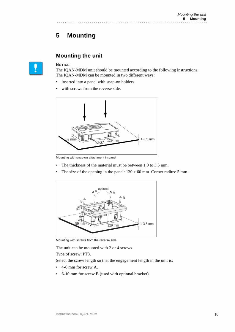
The IQAN-MDM unit should be mounted according to the following instructions. The IQAN-MDM can be mounted in two different ways:
• inserted into a panel with snap-on holders
• with screws from the reverse side.
Mounting with snap-on attachment in panel
• The thickness of the material must be between 1.0 to 3.5 mm.
• The size of the opening in the panel: 130 x 60 mm. Corner radius: 5 mm.
Mounting with screws from the reverse side
The unit can be mounted with 2 or 4 screws.
Type of screw: PT3.
Select the screw length so that the engagement length in the unit is:
• 4-6 mm for screw A.
• 6-10 mm for screw B (used with optional bracket).
"click"1-3,5 mm129 mm59 mm
1-3,5 mm129 mm59 mm
optionalA
BB
A
10Instruction book, IQAN- MDM
Mounting the unit5 Mounting
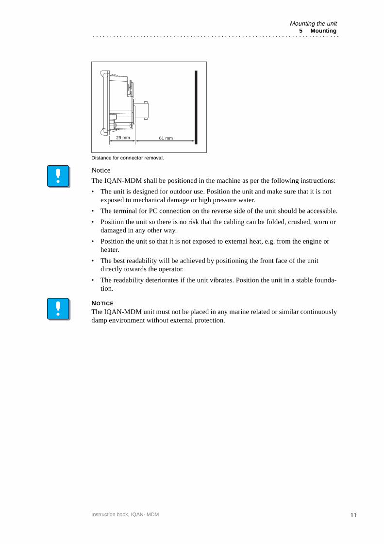
Distance for connector removal.
Notice
The IQAN-MDM shall be positioned in the machine as per the following instructions:
• The unit is designed for outdoor use. Position the unit and make sure that it is not exposed to mechanical damage or high pressure water.
• The terminal for PC connection on the reverse side of the unit should be accessible.
• Position the unit so there is no risk that the cabling can be folded, crushed, worn or damaged in any other way.
• Position the unit so that it is not exposed to external heat, e.g. from the engine or heater.
• The best readability will be achieved by positioning the front face of the unit directly towards the operator.
• The readability deteriorates if the unit vibrates. Position the unit in a stable founda-tion.
NOTICE
The IQAN-MDM unit must not be placed in any marine related or similar continuously damp environment without external protection.
61 mm29 mm
11Instruction book, IQAN- MDM
Connector C16 Installation
6 Installation
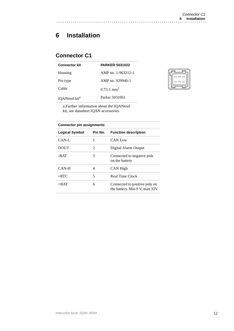
Connector C1
Connector kit PARKER 5031022
Housing AMP no. 1-963212-1
Pin type AMP no. 929940-1
Cable 0.75-1 mm2
IQANtool kita
a.Further information about the IQANtoolkit, see datasheet IQAN accessories
Parker 5031061
Connector pin assignments
Logical Symbol Pin No. Function description
CAN-L 1 CAN Low
DOUT 2 Digital Alarm Output
-BAT 3 Connected to negative pole on the battery
CAN-H 4 CAN High
+RTC 5 Real Time Clock
+BAT 6 Connected to positive pole on the battery. Min 9 V, max 32V
12Instruction book, IQAN- MDM
Supply Voltage6 Installation
Supply VoltageBefore any installation of the IQAN system can take place, make sure the ignition lock is turned off and the battery is disconnected.
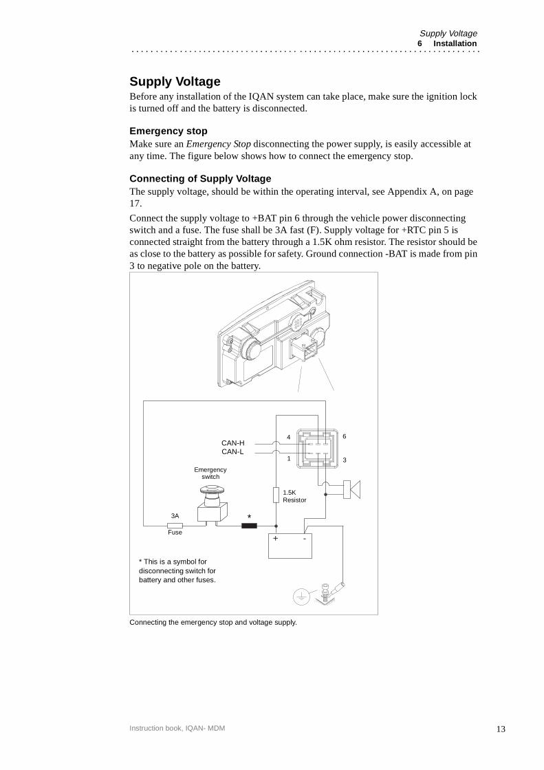
Emergency stopMake sure an Emergency Stop disconnecting the power supply, is easily accessible at any time. The figure below shows how to connect the emergency stop.
Connecting of Supply VoltageThe supply voltage, should be within the operating interval, see Appendix A, on page 17.
Connect the supply voltage to +BAT pin 6 through the vehicle power disconnecting switch and a fuse. The fuse shall be 3A fast (F). Supply voltage for +RTC pin 5 is connected straight from the battery through a 1.5K ohm resistor. The resistor should be as close to the battery as possible for safety. Ground connection -BAT is made from pin 3 to negative pole on the battery.
Connecting the emergency stop and voltage supply.
+ -
CAN-L
*
Emergency
3A
1.5K
64
1 3
switch
CAN-H
* This is a symbol for disconnecting switch for battery and other fuses.
Fuse
Resistor
13Instruction book, IQAN- MDM

IQAN-MDM addressing/terminating6 Installation
IQAN-MDM addressing/terminating
AddressingIQAN-MDM shall not be addressed because there is only one in every system.
TerminatingTermination shall not be done as it is built-in to the IQAN-MDM.
14Instruction book, IQAN- MDM
Start-up procedures7 Start-up
7 Start-up
Start-up proceduresThis chapter contains instructions for action to be taken in connection with the initial start.
WARNING
Risk of injury!If the control system is not fitted properly, the machine could move uncontrollably. The machine’s engine shall not be started before the control system is completely fitted and its signals are verified.
Starting the control system
Start the control system as follows:
• Prior to start, all modules and cables are to be fitted correctly.
• Check fuses, i.e. make sure that the supply voltage to the modules is equipped with the correct fuse.
• Make sure that connections for supply voltage and return lines are correct in the cable’s conductor joint.
• Make sure the emergency stop works.The emergency stop should disconnect the supply voltage to all modules.
Alternatively, the emergency stop may also shut off the diesel engine or a dump valve, and with that depressurize the hydraulic system.
Prepare for system start
WARNING
Make sure no one is in dangerous proximity to the vehicle to avoidinjuries when it starts.
Prepare for the initial system start as follows:
• The engine for the hydraulic system’s pump shall be in off position.
• Make sure that all connectors are properly connected.
• Turn on the control system.
• Make sure that voltage is being supplied to all modules, the green diode shall be illuminated on all modules. Also make sure that master is in contact with all mod-ules by reading the master’s display. Error messages are displayed if the master is not in contact with one or more of the modules.
• Make sure the emergency stop is functioning properly.
15Instruction book, IQAN- MDM
Start-up procedures7 Start-up
Start the system
Start the system as follows:
• Start the engine for the hydraulic system’s pump, assuming that the above men-tioned inspections have been carried out and shown correct values.
• Calibrate and adjust input and output signals according to the instructions related to the master menu system and check each and every output function carefully.
• In addition to these measures, the machine shall also meet the machine directives for the country in question.
16Instruction book, IQAN- MDM
IQAN-MDM Technical OverviewAppendix A
Appendix A
IQAN-MDM Technical Overview
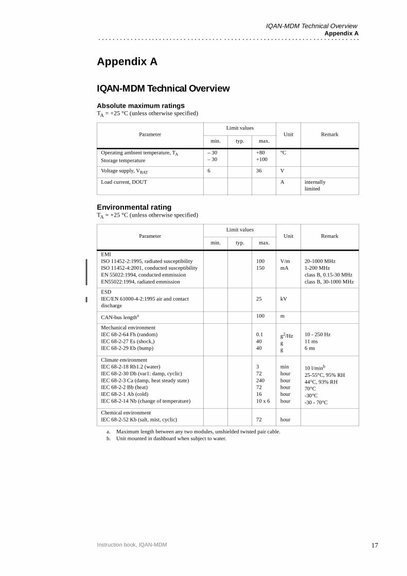
Absolute maximum ratingsTA = +25 °C (unless otherwise specified)
Environmental ratingTA = +25 °C (unless otherwise specified)
ParameterLimit values
Unit Remarkmin. typ. max.
Operating ambient temperature, TA
Storage temperature
– 30– 30
+80+100
°C
Voltage supply, VBAT 6 36 V
Load current, DOUT A internally limited
ParameterLimit values
Unit Remarkmin. typ. max.
EMIISO 11452-2:1995, radiated susceptibilityISO 11452-4:2001, conducted susceptibilityEN 55022:1994, conducted emmissionEN55022:1994, radiated emmission
100150
V/mmA
20-1000 MHz1-200 MHzclass B, 0.15-30 MHzclass B, 30-1000 MHz
ESDIEC/EN 61000-4-2:1995 air and contact discharge
25 kV
CAN-bus lengtha
a. Maximum length between any two modules, unshielded twisted pair cable.
100 m
Mechanical environmentIEC 68-2-64 Fh (random)IEC 68-2-27 Es (shock,)IEC 68-2-29 Eb (bump)
0.14040
g2/Hzgg
10 - 250 Hz11 ms6 ms
Climate environmentIEC 68-2-18 Rb1.2 (water)IEC 68-2-30 Db (var1: damp, cyclic)IEC 68-2-3 Ca (damp, heat steady state)IEC 68-2-2 Bb (heat)IEC 68-2-1 Ab (cold)IEC 68-2-14 Nb (change of temperature)
372240721610 x 6
minhourhourhourhourhour
10 l/minb
25-55°C, 95% RH44°C, 93% RH70°C-30°C-30 - 70°C
b. Unit mounted in dashboard when subject to water.
Chemical environmentIEC 68-2-52 Kb (salt, mist, cyclic) 72 hour
17Instruction book, IQAN-MDM
IQAN-MDM Technical OverviewAppendix A
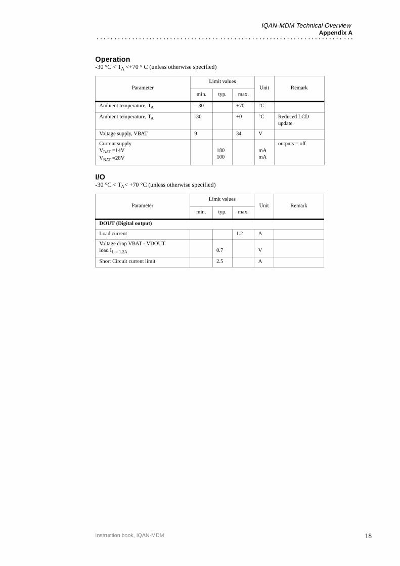
Operation-30 °C < TA <+70 ° C (unless otherwise specified)
I/O-30 °C < TA< +70 °C (unless otherwise specified)
ParameterLimit values
Unit Remarkmin. typ. max.
Ambient temperature, TA – 30 +70 °C
Ambient temperature, TA -30 +0 °C Reduced LCD update
Voltage supply, VBAT 9 34 V
Current supplyVBAT =14V
VBAT =28V
180100
mAmA
outputs = off
ParameterLimit values
Unit Remarkmin. typ. max.
DOUT (Digital output)
Load current 1.2 A
Voltage drop VBAT - VDOUTload IL = 1.2A 0.7 V
Short Circuit current limit 2.5 A
18Instruction book, IQAN-MDM

Error codes, messages and actionsAppendix B
Appendix B
Error codes, messages and actionsIf one of the following error is detected, a message will be presented on the display.
WARNING
An error message could indicate that a hazardous situation exists. If precautions are not taken, this could result in death, serious injury or major property damage.
The following sections will present what measures to take for different error situations put into appropriate context.
LOW/ HIGH SUPPLY VOLTAGE
VREF ERROR
MODULE IS OFFLINE
HIGH TEMPERATURE
Error code Situation Action MDM Comment
Error 1 +BAT < 8,5V - Check voltage supply
Error 1 +BAT > 34V - Check voltage supply
Error code Situation Action MDM Comment
Error 1 VREF < 4,9 V - Check voltage
Error 1 VREF > 5,1 V - Check voltage
Error code Situation Action MDM Comment
Error 3
Error 6
CAN-bus interrupt
Software error
All outputs shut offThe module turns off
Check CAN-bus
Contact supplier
Error code Situation Action MDM Comment
Error 2 Internal temperature> max temp
- Check ambient temperature
Error 4 Internal temperature sensor error
- Contact supplier
19Instruction book, IQAN-MDM
Error codes, messages and actionsAppendix B
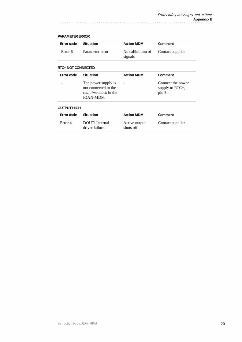
PARAMETER ERROR
RTC+ NOT CONNECTED
OUTPUT HIGH
Error code Situation Action MDM Comment
Error 6 Parameter error No calibration of signals
Contact supplier
Error code Situation Action MDM Comment
- The power supply is not connected to the real time clock in the IQAN-MDM
- Connect the power supply to RTC+, pin 5.
Error code Situation Action MDM Comment
Error 4 DOUT: Internal driver failure
Active output shuts off
Contact supplier
20Instruction book, IQAN-MDM
21
Dimensioning of the IQAN-MDM moduleAppendix C
Instruction book, IQAN-MDM
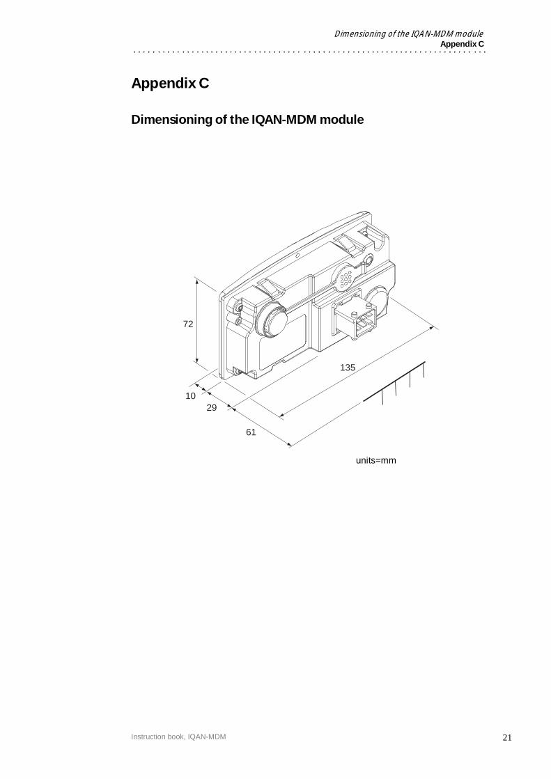
Appendix C
Dimensioning of the IQAN-MDM module
135
29
72
61
10
units=mm

Parker HannifinMobile Controls DivisionSE-435 35 MölnlyckeSwedenTel +46 31 750 44 00Fax +46 31 750 44 21www.parker.com
Parker HannifinMobile Controls Division203 Pine StreetForest City, NC 28043USATel +1 828 245 3233Fax +1 828 248 9733
Publ. no HY17-8328/UKEdition 06/2007
For the latest information visit our website www.iqan.com Information in this instructionbook is subject to change without notice