instruction book and parts list - lister...
TRANSCRIPT

Instruction Book and Parts List
www.lister-shearing.com
109-11270
If the handpiece is not adequately tensioned, the cutter can fly off.Adjust the tension nut correctly before starting the motor of your shearing machine.
CONTENTS
Page
Setting Comb & Cutter 1
Lubrication 2
Maintenance & Fulcrum Post Setting 3
Removing Backjoints & Main Bush 4
Service Equipment 5Parts Lists 6 - 8
Warning
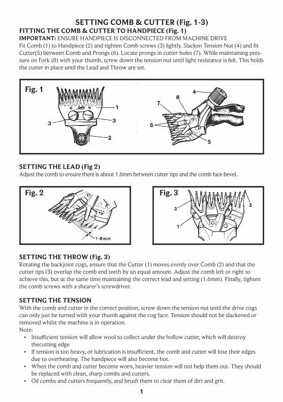
SETTING COMB & CUTTER (Fig. 1-3)FITTING THE COMB & CUTTER TO HANDPIECE (Fig. 1)IMPORTANT: ENSURE HANDPIECE IS DISCONNECTED FROM MACHINE DRIVEFit Comb (1) to Handpiece (2) and tighten Comb screws (3) lightly. Slacken Tension Nut (4) and fit Cutter(5) between Comb and Prongs (6). Locate prongs in cutter holes (7). While maintaining pres-sure on Fork (8) with your thumb, screw down the tension nut until light resistance is felt. This holds the cutter in place until the Lead and Throw are set.
SETTING THE THROW (Fig. 3)Rotating the backjoint cogs, ensure that the Cutter (1) moves evenly over Comb (2) and that the cutter tips (3) overlap the comb end teeth by an equal amount. Adjust the comb left or right to achieve this, but at the same time maintaining the correct lead and setting (1.6mm). Finally, tighten the comb screws with a shearer’s screwdriver.
SETTING THE TENSIONWith the comb and cutter in the correct position, screw down the tension nut until the drive cogs can only just be turned with your thumb against the cog face. Tension should not be slackened or removed whilst the machine is in operation.Note:• Insufficient tension will allow wool to collect under the hollow cutter, which will destroy
thecutting edge• If tension is too heavy, or lubrication is insufficient, the comb and cutter will lose their edges
due to overheating. The handpiece will also become hot.• When the comb and cutter become worn, heavier tension will not help them out. They should
be replaced with clean, sharp combs and cutters.• Oil combs and cutters frequently, and brush them to clear them of dirt and grit.
SETTING THE LEAD (Fig 2)Adjust the comb to ensure there is about 1.6mm between cutter tips and the comb face bevel.
1
Fig. 1
Fig. 2 Fig. 3
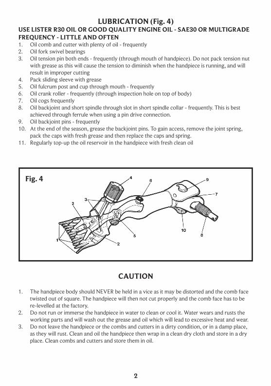
LUBRICATION (Fig. 4)USE LISTER R30 OIL OR GOOD QUALITY ENGINE OIL - SAE30 OR MULTIGRADEFREQUENCY - LITTLE AND OFTEN1. Oil comb and cutter with plenty of oil - frequently2. Oil fork swivel bearings3. Oil tension pin both ends - frequently (through mouth of handpiece). Do not pack tension nut
with grease as this will cause the tension to diminish when the handpiece is running, and will result in improper cutting
4. Pack sliding sleeve with grease5. Oil fulcrum post and cup through mouth - frequently6. Oil crank roller - frequently (through inspection hole on top of body)7. Oil cogs frequently8. Oil backjoint and short spindle through slot in short spindle collar - frequently. This is best
achieved through ferrule when using a pin drive connection.9. Oil backjoint pins - frequently10. At the end of the season, grease the backjoint pins. To gain access, remove the joint spring,
pack the caps with fresh grease and then replace the caps and spring.11. Regularly top-up the oil reservoir in the handpiece with fresh clean oil
CAUTION
1. The handpiece body should NEVER be held in a vice as it may be distorted and the comb face twisted out of square. The handpiece will then not cut properly and the comb face has to be re-levelled at the factory.
2. Do not run or immerse the handpiece in water to clean or cool it. Water wears and rusts the working parts and will wash out the grease and oil which will lead to excessive heat and wear.
3. Do not leave the handpiece or the combs and cutters in a dirty condition, or in a damp place, as they will rust. Clean and oil the handpiece then wrap in a clean dry cloth and store in a dry place. Clean combs and cutters and store them in oil.
Fig. 4
2

MAINTENANCE (Fig. 5)FORK AND PRONGSRight and left hand prongs (1 & 2) swivel independently, and must be oiled and cleaned regularly so that they can move freely. They can be removed by rotating through 90 degrees and withdraw-ing (once the comb and cutter are removed). Alternatively they can be removed by unscrewing the prong retaining spring. Once disassembled, check for wear of the prong cones and pads on the underside, and the prong holes in the fork. Replace if necessary.1. To remove the fork, follow this procedure;2. Remove the comb and cutter3. Remove tension nut and sliding sleeve4. Remove fork retainer screw5. Pull tension pin out ouf fork cup retainer6. Rotate crank to lowest position. The fork can now be withdrawn over the roller and out
through the mouth of the handpiece, leaving the roller in position. If the roller does come off, it can be replaced using a pencil or suitable piece of wire.
IT IS NOT NECESSARY TO ALTER THE FULCRUM POST SETTING.To replace the fork, reverse the above procedure.
FULCRUM POST SETTING PROCEDURE1. Fit comb to handpiece and turn crank roller (5) to bottom position.2. Insert gauge block (6) between comb and prongs.3. Screw down tension nut (7) lightly.4. Slacken fulcrum post locknut (8).5. Insert gauge (4) through hole in body to seat on the fork roller hole.6. Adjust post in or out, maintaining light tension on the tension nut until gauge inner shaft is
level with the top of the gauge barrel when the gauge is pressed down onto the fork roller hole.7. When correctly set, securely tighten locknut (8).
FULCRUM POSTThe fulcrum post (3) is correctly set before leaving the factory. However, when wear eventually occurs on the fulcrum post, fulcrum cup and prongs, fit new components and reset the fulcrum post with a setting gauge (4).
Fig. 5
3
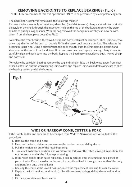
REMOVING BACKJOINTS TO REPLACE BEARINGS (Fig. 6)NOTE: Lister recommends that this operation is ONLY to be performed by a competent engineer.
The Backjoint Assembly is removed in the following manner:Remove the fork assembly as previously described (See Maintenance).Using a screwdriver or similar object, lock the crank through the inspection hole on the top of the body, and unscrew the crank spindle cog using a cog spanner. With the cog removed the backjoint assembly can now be with-drawn from the handpiece body (See Fig.6)
To replace the front bearing, the waved circlip and body seal must be removed. Then, using a screw-driver, tap the slots of the bush to rotate it 90°,in the barrel until slots are vertical. This releases the bearing retainer ring. Using a drift through the body mouth, push the crankspindle, bearing and sleeve out of the back of the handpiece. Unscrew crank head and replace bearing. Using a mandrel carefully align and push back into the body. Replace the bearing retainer, sleeve bush, waved circlip and body seal.
To replace the backjoint bearing, remove the cog and spindle. Take the backjoints apart from each other. Gently tap out the worn bearing using a drift and replace using a mandrel taking care to align the bearing perfectly with the housing.
WIDE OR NARROW COMB, CUTTER & FORKIf the Comb, Cutter and Fork are to be changed from Wide to Narrow or vice versa, follow this procedure:
1. Remove the comb and cutter2. Unscrew the fork retainer screw, remove the tension nut and sliding sleeve3. Pull the tension pin out of the retaining spring4. Turn crank to bottom position, and withdraw the fork over the roller, leaving it in position. It is
not necessary to alter the fulcrum post setting.5. If the roller comes off or needs replacing, it can be refitted onto the crank using a pencil or
piece of wire. Place the roller on the end of a pencil and feed it through the mouth of the body and transfer it onto the crank pin
6. Keeping the crank at the lowest position, insert the replacement fork and fit over the roller.7. Replace the fork retainer, tension pin (ball end in retaining spring), sliding sleeve and tension
nut.8. Fit the appropriate comb and cutter.
Fig. 6
4
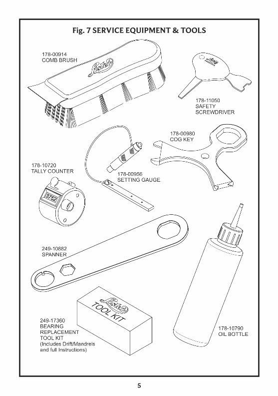
Fig. 7 SERVICE EQUIPMENT & TOOLS
5
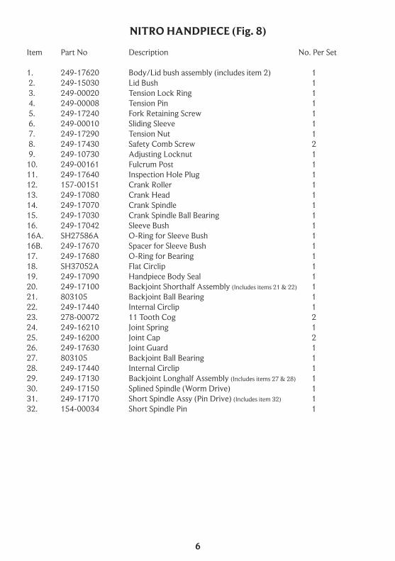
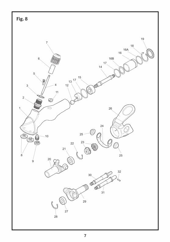
NITRO HANDPIECE (Fig. 8)
Item Part No Description No. Per Set
1. 249-17620 Body/Lid bush assembly (includes item 2) 1 2. 249-15030 Lid Bush 1 3. 249-00020 Tension Lock Ring 1 4. 249-00008 Tension Pin 1 5. 249-17240 Fork Retaining Screw 1 6. 249-00010 Sliding Sleeve 1 7. 249-17290 Tension Nut 1 8. 249-17430 Safety Comb Screw 2 9. 249-10730 Adjusting Locknut 110. 249-00161 Fulcrum Post 111. 249-17640 Inspection Hole Plug 112. 157-00151 Crank Roller 113. 249-17080 Crank Head 114. 249-17070 Crank Spindle 115. 249-17030 Crank Spindle Ball Bearing 1 16. 249-17042 Sleeve Bush 116A. SH27586A O-Ring for Sleeve Bush 116B. 249-17670 Spacer for Sleeve Bush 117. 249-17680 O-Ring for Bearing 118. SH37052A Flat Circlip 119. 249-17090 Handpiece Body Seal 120. 249-17100 Backjoint Shorthalf Assembly (Includes items 21 & 22) 121. 803105 Backjoint Ball Bearing 122. 249-17440 Internal Circlip 123. 278-00072 11 Tooth Cog 224. 249-16210 Joint Spring 125. 249-16200 Joint Cap 226. 249-17630 Joint Guard 127. 803105 Backjoint Ball Bearing 128. 249-17440 Internal Circlip 129. 249-17130 Backjoint Longhalf Assembly (Includes items 27 & 28) 130. 249-17150 Splined Spindle (Worm Drive) 131. 249-17170 Short Spindle Assy (Pin Drive) (Includes item 32) 132. 154-00034 Short Spindle Pin 1
6
17
Fig. 8
7
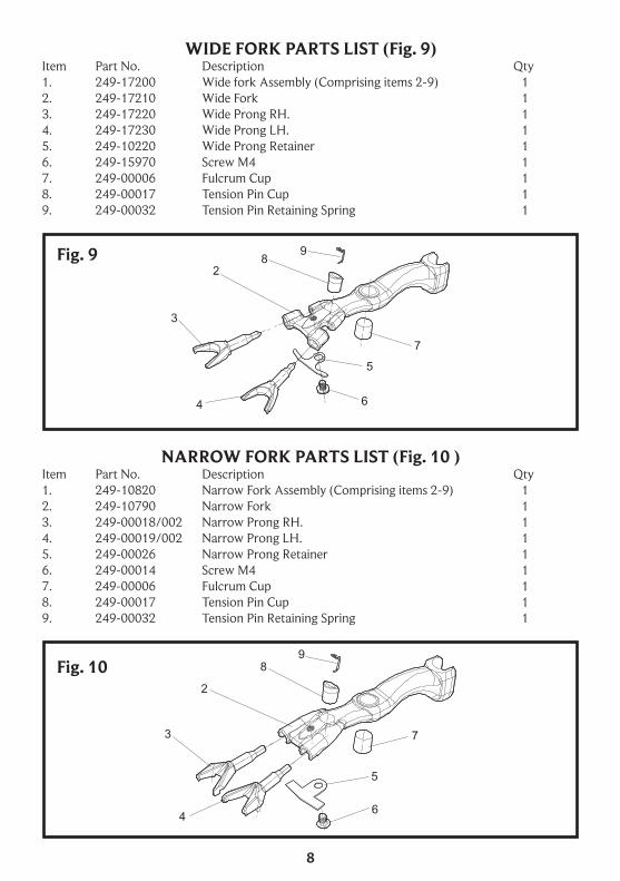
WIDE FORK PARTS LIST (Fig. 9)Item Part No. Description Qty1. 249-17200 Wide fork Assembly (Comprising items 2-9) 12. 249-17210 Wide Fork 13. 249-17220 Wide Prong RH. 14. 249-17230 Wide Prong LH. 15. 249-10220 Wide Prong Retainer 16. 249-15970 Screw M4 17. 249-00006 Fulcrum Cup 18. 249-00017 Tension Pin Cup 19. 249-00032 Tension Pin Retaining Spring 1
NARROW FORK PARTS LIST (Fig. 10 )Item Part No. Description Qty1. 249-10820 Narrow Fork Assembly (Comprising items 2-9) 12. 249-10790 Narrow Fork 13. 249-00018/002 Narrow Prong RH. 14. 249-00019/002 Narrow Prong LH. 15. 249-00026 Narrow Prong Retainer 16. 249-00014 Screw M4 17. 249-00006 Fulcrum Cup 18. 249-00017 Tension Pin Cup 19. 249-00032 Tension Pin Retaining Spring 1
Fig. 9
Fig. 10
8

WARRANTY AND REPAIRItems requiring repair or attention under warranty should be returned to the dealer from whom it was purchased. In case of difficulty contact the Lister Shearing factory:
Lister Shearing Equipment LimitedLong Street, Dursley, Gloucestershire. Gl11 4HR
Tel: +44 (0) 1453 544830E-mail: [email protected]
ORDERING SPARESWhen ordering spare parts, always quote the PART NUMBER and DESCRIPTION to avoid confu-sion. Whenever possible quote the HANDPIECE SERIAL NUMBER which will be found on the underside of the body.
9

Lister Shearing Equipment LtdDursley, Gloucestershire, GL11 4HR
Tel: +44 (0) 1453 544 830Email : [email protected]
www.lister-shearing.com
A Subsidiary of Clipper Corporation
LS-08-1212-A-A