instruction book and parts list - lister shearing · instruction book and parts list solid or...
TRANSCRIPT

Instruction Book and Parts List
Solid or Flexible Drive, Standard fit or QR (Quick Release), Pin or Worm Drive
www.lister-shearing.com
109-10950
NEXUS NEXUS
NEXUS PRO
NEXUS PRO

ELECTRICITY CAN BE DANGEROUS IF ABUSED
• The set is supplied with a moulded on plug. Should this plug ever need replacing, the leads in the mains lead are coloured in accordance with the following code: green/yellow - earth, blue - neutral, brown - live
• The motor must be protected by a 13A fuse
• The electricity supply must conform to the standards prescribed by the Institute of Electrical Engineers (UK only) or other approved standards (Other markets)
• Maintain mains cable and shearing set in good condition and have tested regularly by a qualified electrical engineer.
• The mains cable must include an earth lead - ensure it is in good condition. For added safety include either a portable earth leakage trip or an earth leakage trip in the mains circuit.
• Hang cable clear of working area.
• The electrical equipment is not waterproofed. Always keep and use in dry conditions.
• To ensure no strain is imposed on the mains cable, restrain the shearing set to stop it rotating.
• Disconnect from mains supply before dismantling set.
• To protect shearers feet when handpiece is left unattended during shearing, place handpiece underside flat on the floor
SEE ALSO : ELECTRICAL & SAFETY INSTRUCTIONS LEAFLET - 109-10840
Warning

1
CONTENTS
Page No:
SAFETY Inside Front Cover
INTRODUCTION 2GETTING STARTED / SETTING UP
Connecting Flexible Drive 2Working Height (Flexible Drive) 3
SOLID DRIVE
Connecting Solid Drive 4-5Working Height (Solid Drive) 6
CHANGING SPEED 6‘SENSOR’ OVERLOAD CUT-OUT 6MAINTENANCE & LUBRICATION 7PARTS LISTS
Motor Unit 8-9Switch & Sensor 10-11Ordering Spares 10Flexible Drive & Hanging Bracket 12-13Solid Drive 14-15
WARRANTY & REPAIR
Wiring Diagrams 16SERVICE EQUIPMENT AVAILABLE Inside Back Cover

2
INTRODUCTION
The Nexus shearing set is a mains operated machine with three speed settings. Standard pulleys give 2800, 3200 & 3500 RPM. The optional “Lo-Range” pulley set gives speeds of 2000, 2800 & 3500 RPM. The fastest speed setting is on the lower grooves (i.e. next to the top plate). The drive belt is automatically tensioned correctly by a compression spring, and will not require adjustment.
The machine is operated by a pull switch, pull once for on, pull again to switch off. Before connecting your drive, ensure the motor is in the off position. Drive connection is ex-plained later.
Make sure to read and understand the instruction book supplied with your handpiece. Always have a good supply of sharp, clean combs and cutters when shearing, and change them when necessary. With proper care, maintenance and lubrication your Nexus set should give years of trouble free shearing.
GETTING STARTED / SETTING UP
CONNECTING A STANDARD FLEXIBLE DRIVE (Fig.1a)
1. Slacken top sleeve nuts and expose the bayonet joint attached to the inner.2. Push bayonet joint onto the machine drive spindle against the spring. Hold the drive
spindle still and rotate the bayonet joint so that the drive spindle pin engages into the L-shaped slot in the bayonet joint.
3. Push the top sleeve right up over the spindle bearing and tighten the top nut.4. With the drive hanging straight, adjust the flexible outer up or down until the bottom
joint projects through the end ferrule by about 20mm (3/4”) as shown in Figure 3. Tighten the lower top sleeve nut.
CONNECTING A QUICK RELEASE FLEXIBLE DRIVE (Fig.1b)
1. Open the quick release clamp and push the top sleeve right up over the spindle bear-ing until it hits the end stop. Twist it as it goes up if necessary to encourage the spline drive spindle to engage with the quick release joint.
2. Close the quick release clamp and check that the drive is hanging securely. If it is not secure, re-open the clamp and tighten the adjusting nut to increase the clamping force before closing the clamp again. Repeat as necessary.
3. The sheath assembly position is preset so that the top end of the sheath assembly is 118mm (4 5/8”) from the top end of the top sleeve. This ensures that the spline drive spindle engages correctly with the quick release joint and causes the bottom joint to project from the end ferrule by about 20mm (3/4”) as in Fig. 3.

3
WORKING HEIGHT - FLEXIBLE DRIVE (Fig.2)
The set should be suspended, with the flexible drive hanging straight down, so there is 25mm (1”) between the end of the flexible drive inner and the floor or work-ing area. To make sure there is no undue strain on the mains lead or flexible drive, the machine should be se-curely fixed to a wall, beam or shearing trailer to prevent it rotating when operating the pull switch.
Fig. 1a
FlexibleDrive
FlexibleDrive
FlexibleDrive
FlexibleDrive
Spindle Bearing
Spindle Bearing
AdjustingNut
Spline DriveSpindle
QuickReleaseClamp
Drive Spindle
Bayonet Joint
Top Wingnutor Tommy Nut
Top Sleeve
Bottom Wingnutor Tommy Nut
Fig. 1b
Fig. 3
Fig. 2

4
CONNECTING & DISCONNECTING THE HANDPIECE
Set the comb and cutter as explained in the handpiece instruction book, and tension cor-rectly. Screw the ferrule onto the backjoint tightly. Holding the handpiece in one hand and the end of the drive in the other, insert the drive into the ferrule. Press the handpiece firmly onto the drive and rotate the handpiece clockwise to engage the drive pin (or worm drive). Make sure there is enough tension on the handpiece to prevent the cutter moving easily during engagement.
To remove handpiece from the drive, switch off the machine. Push the handpiece onto drive and, maintaining pressure, rotate anti-clockwise until pin (or worm drive) is disen-gaged. Handpiece will now disconnect.
SOLID DRIVE
ASSEMBLY OF SOLID DRIVE (Fig.4a)1. Slide ferrule onto bottom (plain) end of the long tube.2. Hook the tube joint assembly, (either spindle eye) onto the hook at the bottom end of
the long inner core (inside the long tube).3. Slide the ferrule down the long tube and screw onto the threaded end of the tube
joint assembly. Tighten securely.4. Hook the other end of the tube joint assembly onto the short inner core.5. Slide the short tube over the short inner core and tighten the nut onto the tube joint
assembly so that the end of the bayonet joint protrudes 3mm (1/8”).
CONNECTING A STANDARD SOLID DRIVE (Fig.4b)1. Slacken top sleeve nuts. Push exposed bayonet joint onto the machine drive spindle
against the spring. Hold the drive spindle still and rotate the bayonet joint so that the drive spindle pin engages into the L-shaped slot in the bayonet joint.
2. Push the top sleeve right up over the spindle bearing and tighten the top nut.3. Slide the long tube/spring assembly up inside the top sleeve until approx 216mm
(8½”) of spring is exposed, then tighten the lower top sleeve nut. This ensures correct clearance at the end of the long tube inside the ferrule.
CONNECTING A QUICK RELEASE SOLID DRIVE (Fig.4c)1. Open the quick release clamp and push the top sleeve right up over the spindle bear-
ing until it hits the end stop. Twist it as it goes up if necessary to encourage the spline drive spindle to engage with the quick release joint.
2. Close the quick release clamp and check that the drive is hanging securely. If it is not secure, re-open the clamp and tighten the adjusting nut to increase the clamping force before closing the clamp again. Repeat as necessary.
3. The tube spring position is preset so that the top end of the top spring is4. 118mm (4 5/8”) from the top end of the top sleeve. This ensures that the spline drive
spindle engages correctly with the quick release joint and ensures correct clearance at the end of the long tube inside the ferrule.

5
Fig. 4a
Fig. 4b
Fig. 4c
SpindleEye
Tube JointAssembly
Long Tube
End Of Long Tube Must Not Bottom Out Here
Short TubeNut
Tube Joint Assembly
BayonetJoint
3mm(1/8”)
Ferrule
Gut Hook
Spindle Bearing
Spindle Bearing
Drive Spindle
SplineDrive Spindle
QuickReleaseClamp
Tube Spring
Adjusting Nut
Bayonet Joint
Top Wingnutor Tommy Nut
Oil Hole Must Not Be Blocked
Tube SpringTop Sleeve
Bottom Wingnutor Tommy Nut

6
WORKING HEIGHT - SOLID DRIVE (Fig5.)
With the handpiece removed, the set should be suspended so that when the solid drive hangs down freely, there is just 1mm between the end of the drive joint and the working surface. The machine should be securely & rigidly fixed to a wall, beam or shearing trailer so that it does not move during operation. This allows the tube spring to function properly.
‘SENSOR’ OVERLOAD CUT-OUT
The NEXUS SENSOR and NEXUS PRO SENSOR are fitted with an automatic cut-out which will operate if an overload situation arises. This ‘Sensor’ will automatically switch off the power to the motor, and the handpiece may also disconnect. This is normal. If this happens, check the handpiece and comb & cutter for faults or obstructions before resum-ing shearing. The pull switch will need to be pulled once to reset the Sensor and a second time to restart the motor.
Note: Under certain circumstances, when an obstruction is hit, the drive may disengage from the machine before the Sensor cut-out can operate. This is normal and does not signify a faulty Sensor.
Fig. 5
CHANGING SPEED (Fig.6)
1. Remove top cover screws and top cover with allen key provided.2. Move the drive belt to the required position by pushing the spindle bearing towards
the motor to reduce belt tension, then move the belt to required grooves.3. Ensure the belt is correctly positioned in both pulley grooves to eliminate belt/pulley
wear.4. Replace top cover and screws.
Fig. 6

7
MAINTENANCE & LUBRICATION (Fig. 7)
The NEXUS, when properly cared for, should give years of trouble-free shearing. To keep machine and drive in the best possible condition, follow these simple instructions:
1. Make sure machine is fixed securely when shearing to prevent strain on the electric cable.
2. Keep air vents clear form blockages.3. Ensure the drive spindle is regularly oiled through the oil hole in the spindle bearing
during shearing. DO NOT over-oil as this can lead to oil getting onto the drive belt and causing slip and loss of drive.
4. Periodically check the pulley drive belt for signs of wear, and change if required. Make sure the top plate is clean and free from oil. A worn or oily belt can make the pulleys “slip”.
5. When shearing make sure the flexible or solid drive is regularly oiled at all the correct places (See Fig.7).
6. When not shearing, store flexible drives straight or with minimum bending. Flexible inners should be lightly greased and solid cores oiled at the end of the season before storing.
Fig. 7

8
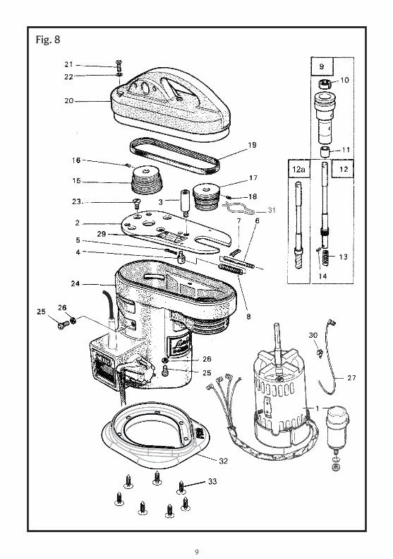
PARTS LIST - MOTOR UNIT (Fig 8.)
Item Part Number Description No. per Set
1 289-17020 250W Motor & Capacitor 240V 50Hz 1 or 289-17780 250W Motor & Capacitor 110V 60Hz 1 or 289-18840 700W ‘PRO’ Motor & Capacitor 240V 50Hz 1 2 289-17550 Top Plate 1 3 289-17560 Top Plate Stud 3 4 289-10842 Spring Abutment 1 5 027-00123 Split Pin 1 6 289-17570 Spring Bar 1 7 027-00122 Split Pin 1 8 289-17580 Spring 1 9 289-10091 Spindle Bearing Assy (Includes Items 10 & 11) 110 289-00020 Ball Bearing 111 289-00011 Bush 112 289-14400 Drive Spindle Assy (Includes items 13 & 14) 1 or 12a 289-18900 Spline Drive Spindle (for ‘Quick Release’) 113 289-11601 Spring 114 154-00034 Drive Pin 115 289-17600 Driving Pulley 240V 50HZ 1 or 289-17602 Driving Pulley 110V 60Hz 116 289-14360 Grubscrew M5 (W-cup Point) 117 289-17610 Driven Pulley 118 289-14370 Grubscrew M5 (Dog Point) 119 289-13720 Poly-V Belt 120 289-00043 Green Top Cover 1 or 289-18530 Green ‘Sensor’ Top Cover 1 or 289-00043/ORA Orange Top Cover 1 or 289-18930 Orange ‘Sensor’ Top Cover 121 289-17740 Screw M8 x 25 (Hex Socket Button Head) 322 027-03929 Washer (Fan Disc Type) 323 289-17710 Screw M6 x 16 (C’sk Head) 424 289-17650 Grey Bottom Cover 1 or 289-17650/CEN Black Bottom Cover 125 289-17090 Screw M5 x 10 (Hex Socket Button Head) 526 289-17540 Washer 527 289-17620 Capacitor to Switch Lead 129 289-17660 Speed Change Label 130 289-17680 Piggyback Terminal (if required) 131 289-17940 Spring Clip for Spindle Bearing 132 289-18860 Rubber Foot (NEXUS PRO / PRO SENSOR) 133 289-18870 Barbed Rivet (NEXUS PRO / PRO SENSOR) 7
OPTIONAL EXTRA FOR 240V ONLY - (See Fig 13.): 289-18570 Lo-Range Pulley Kit for 2000, 2800 & 3500 RPM
9
Fig. 8

10
PARTS LIST - SWITCH & SENSOR (Fig.9)
Item Part Number Description No. Per Set
2 289-14820 Mains Lead 3-core UK Plug 1 or 289-14821 Mains Lead 3-core USA Plug 1 or 289-14822 Mains Lead 3-core AUS Plug 1 or 289-16210 Mains Lead 3-core EURO Plug 1 3 258-37070 Grommet 1 4 289-14250 Cable Clamp & Bridge 1 5 289-14260 Screw No.4 x 9.5mm 2 6 289-14270 Screw No.4 x 16mm 2 7 289-14580 Switch Assembly 1 or 289-14581 20 Amp Switch Assembly 1 (use for NEXUS 110V and NEXUS PRO / PRO SENSOR 240V) 8 289-15390 Arrow Label 2 9 289-15020 Ratchet Wheel 210 289-15040 Ratchet Spring 111 289-15250 Switch Lever Assembly 1 (Comprising items 12-17)12 289-15030 Ratchet Shaft 113 289-15050 Ratchet Housing 114 289-15080 Return Spring 115 289-15060 Switch Lever 116 289-15980 Grubscrew M5 x 8 (Full Dog-Point) 117 289-15990 Grubscrew M5 x 6 (Cone Point) 118 289-15130 Grubscrew M5 x 10 (Cone Point) 319 289-17910 Split Ring 120 289-17920 Rope Assembly 1 (Includes item 19)21 289-18510 Sensor Cut-out PCB 240V 1 (for NEXUS SENSOR 240V) or 289-18880 PRO Sensor Cut-out PCB 240V 1 (for NEXUS PRO SENSOR 240V)
ORDERING SPARES
Should you ever need to order spares for your machine or drive, always quote the PART NUMBER and DESCRIPTION. Where possible state the MACHINE or DRIVE TYPE and SERIAL NUMBER of the machine which will be found on the specification plate attached to the bottom cover. This will help us speed up your order, and overcome any confusion by ordering the wrong spares.

11
Fig. 9

12
PARTS LIST - FLEXIBLE DRIVE & HANGING BRACKET (Fig.10)
Item Part Number Description No. Per Set
1 177-10220 Standard Top Sleeve Assembly 1 (Comprising items 2, 3, 4)1a 177-10710 Quick Release Top Sleeve Assembly 1 (Comprising items 2, 3, 4a, 4b)2 177-00964 Sleeve Assembly 1 3 177-10570 Nib Head Bolt M8 x 32mm 1-24 177-10620 Tommy Nut M8 24a 177-10690 Quick Release Clamp Assembly 14b 177-10650 Security Nut M8 15 289-14430 Standard Shaft & Sheath Complete (Pin Drive) 1 (Comprising items 6, 8, 9 at top, 9 at bottom) or 289-14450 Standard Shaft & Sheath Complete (Worm) 1 (Comprising items 6, 8, 9 at top, 9b at bottom) or 289-14860 Quick Release Shaft & Sheath Complete (Pin) 1 (Comprising 1a, 6, 8, 9a at top, 9 at bottom) or 289-14870 Quick Release Shaft & Sheath Complete (Worm) 1 (Comprising 1a, 6, 8, 9a at top, 9b at bottom)6 289-14440 Sheath Assembly 17 289-13611 Standard Shaft Assembly with Joints (Pin Drive) 1 (Comprising items 8, 9 at top, 9 at bottom)8 278-12971 Shaft Inner Less Joints 19 176-10000 Bayonet Joint Assembly (Comprising 10 & 11) 1-29a 177-10640 Quick Release Joint (for top end only) 1 9b 177-10560 Worm Drive Joint (for bottom end only) 110 177-00889 Spring 1-211 173-00754 Bayonet Joint 1-212 177-00871 Ferrule for Flexible Drive 1
HANGING BRACKET - OPTIONAL EXTRA
13 289-18950 Universal Hanging Bracket Complete (Includes items 14-17)14 289-18960 Bracket 115 289-18970 Bolt M6 x 60 216 289-18980 Nut 217 289-18990 Spring Washer 2
Note: Hanging bracket is suitable for either solid or flexible drive machines

13
Fig. 10

14
PARTS LIST - SOLID DRIVE (Fig 11)
Item Part Number Description No. Per Set1 289-10990 Standard Downtube Complete (Pin Drive) 1 or 289-11000 Standard Downtube Complete (Worm Drive) 1 or 289-11130 Quick Release Downtube Complete (Pin Drive) 1 or 289-11120 Quick Release Downtube Complete (Worm) 1 2 177-00963 Standard Long Tube Assembly 1 (Comprising items 3, 5, 7, 8 & 10)2a 177-10700 Quick Release Long Tube Assembly 1 (Comprising items 3a, 5, 7, 8 & 10)3 177-10220 Standard Top Sleeve Assembly (Comprising items 4, 5, 6) 1 3a 177-10710 Quick Release Top Sleeve Assembly 1 (Comprising items 4, 5, 6a, 10) 4 177-00964 Sleeve Assembly 15 177-10570 Nib Head Bolt M8 x 32 1-46 177-10620 Tommy Nut M8 26a 177-10690 Quick Release Clamp Assembly 17 177-00853 Tube Spring 18 177-00962 Long Tube Assembly 19 177-10650 Security Nut M8 110 272-00003 Hexagon Nut M8 1-211 177-10300 Standard Long Core Assy (Includes 12 & 13) 111a 177-10720 Quick Release Long Core Assy (Includes 12a & 13) 1 12 173-00754 Bayonet Joint (3-slot) 112a 177-10640 Quick Release Joint 113 177-00870 Gut Hook 114 177-00901 Ferrule for Solid Drive 215 177-00861 Tube Joint Assy Complete (Comprising 16-21) 116 177-00980 Tube Joint Bearings Matched Pair (Includes 17) 117 177-00879 Tube Joint Screw 118 177-00863 Tube Joint Spindle 219 177-00864 Cog for Solid Downtube 220 177-10590 Tube Joint Guard 121 177-10600 Tube Joint Push Rivet 222 177-00968 Short Tube Assembly Complete 1 (Comprising items 5, 10, 23)23 177-00967 Short Tube Assembly 126 177-10310 Short Core Assy - Pin Drive (Includes 27 & 28) 126a 177-00860SC Short Core Assy - Worm Drive (Includes 27 & 29) 127 177-00870 Gut Hook 128 177-00868T Bayonet Joint (2-slot) 129 177-10560 Worm Drive Joint 130 177-10680 Optional Rope Guide Kit (Comprising 10, 31, 32) 131 177-10660 Rope Guide 132 177-10670 Extended Hexagon Nut M8 1

15
Fig. 11

16
WARRANTY & REPAIR
Items requiring repair or attention under warranty should be returned to the dealer from whom it was purchased. In case of difficulty contact the Lister Shearing factory. See back cover for contact details.
WIRING DIAGRAMSWARNING! Electrical Repairs must only be undertaken by qualified persons!
Fig. 12a - Nexus / Nexus Pro
Fig. 12b - Nexus Sensor / Nexus Pro Sensor

17
Fig. 13 - Available Service Equipment

Lister Shearing Equipment LtdDursley, Gloucestershire, GL11 4HR
Tel: +44 (0) 1453 544 832Email : [email protected]
www.lister-shearing.com
A Subsidiary of Clipper CorporationLS-08-0312-B-A
TECHNICAL DATA
MOTOR RATED VOLTAGE (check rating plate) 220-240V 50Hz - Single Phase or 110-115V 60 Hz - Single PhaseMOTOR POWERNexus: 250W (1/3 HP)Nexus Pro: 700W (1 HP)DRIVE SPEEDSStandard Pulleys - Low - 2800 RPM - Top Grooves - Medium - 3200 RPM - Middle Grooves - High - 3500 RPM - Lower GroovesLo-Range Pulleys - Low - 2000 RPM - Top Grooves ( for 240V - Medium - 2800 RPM - Middle Grooves ONLY) - High - 3500 RPM - Lower GroovesWORKING HEIGHT ABOVE GROUNDHang set so that end of drive is 25mm (1”) above ground or working surfaceFLEXIBLE DRIVE SETTINGLower bayonet joint projection 20mm (3/4”)SOLID DRIVE SETTINGLower bayonet joint projection 3mm (1/8”)LUBRICATIONDrive shafts - General purpose greaseOil Holes - Lister R30 oil or SAE 30 or Multigrade