instruction manual illustrated parts list trailer
TRANSCRIPT

TO-136Revised070194
INSTRUCTION MANUAL
with
ILLUSTRATED PARTS LIST
for
TRAILER(5500 Pounds Capacity)
Part Numbers
482731
and
Running Gear Part Numbers
404088A
Manufactured By
HOBART BROTHERS COMPANY
AIRPORT SYSTEMS GROUP
GROUND POWER EQUIPMENT
TROY, OHIO 45373
U.S.A.

This page intentionally left blank.
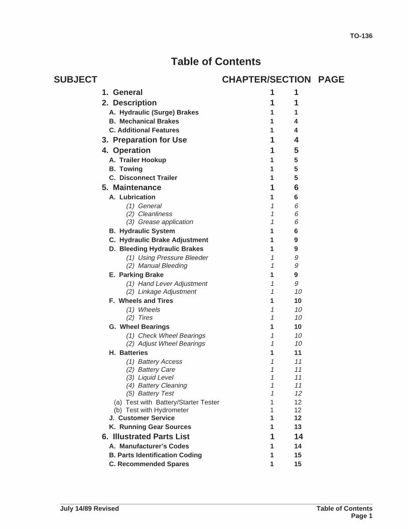
Table of Contents
SUBJECT CHAPTER/SECTION PAGE1. General 1 12. Description 1 1
A. Hydraulic (Surge) Brakes 1 1B. Mechanical Brakes 1 4C. Additional Features 1 4
3. Preparation for Use 1 44. Operation 1 5
A. Trailer Hookup 1 5B. Towing 1 5C. Disconnect Trailer 1 5
5. Maintenance 1 6A. Lubrication 1 6
(1) General 1 6(2) Cleanliness 1 6(3) Grease application 1 6
B. Hydraulic System 1 6C. Hydraulic Brake Adjustment 1 9D. Bleeding Hydraulic Brakes 1 9
(1) Using Pressure Bleeder 1 9(2) Manual Bleeding 1 9
E. Parking Brake 1 9(1) Hand Lever Adjustment 1 9(2) Linkage Adjustment 1 10
F. Wheels and Tires 1 10(1) Wheels 1 10(2) Tires 1 10
G. Wheel Bearings 1 10(1) Check Wheel Bearings 1 10(2) Adjust Wheel Bearings 1 10
H. Batteries 1 11(1) Battery Access 1 11(2) Battery Care 1 11(3) Liquid Level 1 11(4) Battery Cleaning 1 11(5) Battery Test 1 12
(a) Test with Battery/Starter Tester 1 12(b) Test with Hydrometer 1 12
J. Customer Service 1 12K. Running Gear Sources 1 13
6. Illustrated Parts List 1 14A. Manufacturer’s Codes 1 14B. Parts Identification Coding 1 15C. Recommended Spares 1 15
TO-136
July 14/89 Revised Table of ContentsPage 1

This page intentionally left blank
TO-136
Table of Contents July 14/89 RevisedPage 2

FOUR WHEEL TRAILERS1. General
The purpose of the four-wheel trailer (See Fig. 1) is to add mobility to several series of diesel and gasolineengine driven generator sets rated at 37.5, 60, and 90KVA. Different trailer bodies are provided formounting generators driven by Detroit Diesel (GM), Cummins Diesel, and Ford gasoline engines.
2. DescriptionThe trailer is a compact, four-wheel vehicle with a shallow steel frame and full fenders. Enclosed batterycompartments are centrally located on each side between the fenders. These compartments eachaccommodate two 6-volt batteries. Top covers provide quick access to the batteries for service orreplacement.
A fuel tank with a usable capacity of 43 gallons (163 liters), is mounted between the frame rails at therear. An electric fuel gage sending unit is mounted in the tank. The quantity indicating gage is located onthe engine control panel of the generator set. Shallow troughs are provided on both sides of the trailer foroutput cable storage.
The trailer is supported by two axles which are mounted to the frame by four semi-elliptical leaf springs.The rear axle is solid with internal drum-type brakes.
The front axle assembly consists of a solid axle with spindles and steering linkage, and a drawbar whichmay be folded upward when not in use. A spring-loaded latching bracket secures the drawbar in verticalposition when the trailer is parked.
All trailers covered by this manual are equipped with hand-operated parking brakes. In addition, certaintrailers have hydraulically-operated surge brakes. The hydraulic and mechanical braking systems have acommon brakeshoe arrangement (except trailer No. 482731-9).
A. Hydraulic (Surge) Brakes
On trailers equipped with hydraulic brakes, wheel cylinders are connected by tubes and hoses to amaster cylinder mounted on the drawbar (See Fig. 2).
The master cylinder piston is actuated by a compressible type linkage in the drawbar to apply trailerbrakes when the tow vehicle is slowed down by braking or other action. Violent application of trailerbrakes when the tow vehicle is slowed or stopped suddenly is prevented by a shock absorber mountedin the actuating linkage parallel to the master cylinder.
Should the trailer break away from the tow vehicle, an emergency lever attached to the tow vehicle by abreak-away chain will apply hydraulic brakes. When actuated, the emergency lever will remain locked inbraking position until released by disengaging a latching spring. (See Fig. 4).
In addition to providing an emergency stopping capability in case of trailer break-away, the hydraulicbrake system relieves the tow vehicle brake system of the added burden of slowing and stopping thetrailer. It also lessens the possibility of jack-knifing, etc., during sudden stops.
A master cylinder reservoir cap with special venting is used to prevent the escape of fluid from thereservoir when the drawbar is secured in an upright position.
TO-136
July 01/94 Revised Page 1

Four-Wheel TrailersFigure 1
TO-136
Page 2 July 01/94 Revised

Hydraulic Brake MechanismFigure 2
Length 93-3/4 inches (2381 mm) *
Width 78-1/2 inches (1994 mm) *
Height 31-1/4 inches (794 mm) *
Wheelbase 55 inches (1397 mm) *
Tread 65 inches (1651 mm) *
Tires (solid and pneumatic) 6:00 x 9
Tire Pressure 60psi (414 kPa)
Springs Semi-elliptical
Brakes Hydraulic and Mechanical,
2-wheel, rear
Fuel Tank (usable capacity) 43 gallons (163 liters)
Electrical Systems (12-Volt DC Negative Ground)
Ford Engine V8-361 Two 6-Volt batteries in series
Detroit Diesel Engines, Four 6-Volt batteries
3-71N and 4-71N in series-parallel
Cummins Diesel Engines , Four 6-Volt batteries
V6-378 and V8-504 in series-parallel
* Tolerance on dimensions: 1/8-inch (3.17 mm)
Trailer SpecificationsFigure 3
TO-136
July 01/94 Revised Page 3

B. Mechanical Brakes
The mechanical parking brakes are actuated by a hand lever mounted at the forward left corner of thetrailer. (See Fig. 1). Actuating linkage rods (or cables in conduit) connect the lever to the rear rigging,which is housed in a transverse channel attached to the frame just forward of the rear axle. This riggingactuates the brakeshoe to set the brake when the hand lever is pulled forward and outward, and releasesthe brake when the lever is returned to the position shown in Figure 1.
C. Additional Features
(1) Tires are solid rubber or pneumatic type with tubes, size 6:00 x 9.
(2) All wheel bearings are roller type.
(3) Red reflectors are mounted on all four corners of each trailer.
(4) A fire extinguisher, with mounting bracket, is furnished with each trailer.
3. Preparation for Use
Upon delivery, check the unit thoroughly for shipping damage.
A. Check reflectors for broken glass.
B. Check sheet metal for dents and deformation.
C. Check pressure in all four tires.
D. Check batteries for proper fluid level.
E. Check operation of parking brakes.
F. Check hydraulic brake system.
(1) Check for leaks and shipping damage.
(2) Check for brake fluid in master cylinder. If fluid is required, fill master cylinder with an approvedMOTOR VEHICLE BRAKE FLUID. The newest SAE standards for non-petroleum motor vehicle brakefluids are J1702b (Arctic) and J1703b. Approved fluids under the old standards, prior to 1967, were SAE70R1 and 70R3. USE OF IMPROPER FLUID VOIDS ALL BRAKE SYSTEM WARRANTIES.
(3) Make certain that master cylinder cap vent is OPEN and not damaged.
G. Check Fuel Quantity
The electric fuel gage is operational only when the generator engine is running, or when instrument panellights are ON. To check fuel quantity when engine is stopped, turn ON panel lights.
TO-136
Page 4 July 01/94 Revised

4. Operation
To connect trailer to tow vehicle, support drawbar and release latch lever to lower drawbar to towingposition.
WARNING: EXERCISE CARE TO PREVENT INJURY TO PERSONNEL BY AFALLING DRAWBAR.
CAUTION: DO NOT TOW TRAILER FASTER THAN 20 MPH. AVOID SUDDEN TURNS.
A. Trailer Hookup
(1) To attach the trailer to a tow vehicle, connect drawbar towing eye to pintle hook in a normal manner.
(2) On trailers with surge brakes, BE CERTAIN to attach breakaway chain (Fig. 4) to towing vehiclesecurely in a manner and position that will permit normal operation of towing vehicle and trailer, but willassure application of trailer brakes if the two vehicles should accidentally separate. BE SURE thatbreakaway chain does not pull taut while vehicles are connected.
(3) Safety chains may be used at the option of the user. If safety chains are used, they should beattached on opposite sides of trailer drawbar or frame, and crossed under the drawbar in the event of abreakaway. Slack should be just sufficient to permit full turns.
B. Towing
CAUTION: 1. DO NOT TOW TRAILER FASTER THAN 20 MPH.
2. AVOID SUDDEN STARTS, STOPS, AND TURNS.
3. DO NOT ATTEMPT TURNS WHICH ARE TIGHTER THAN THE VEHICLE
COMBINATION IS CAPABLE OF MAKING FREELY (WITHOUT
CRAMPING).
(1) On trailers with surge brakes, check position of breakaway lever before towing. Lever must be fullyreleased (pointing all the way back to the trailer) for normal towing. (See Fig. 4). No teeth on breakawaylever should be engaged by latch spring. Accidental operation of lever will cause trailer brakes to drag,heat up, and possibly burn out. To disengage spring latch, insert the blade of a screwdriver under springand pry it upward.
(2) Do not attempt turns tighter than your vehicle combination is capable of making. Tight turns andjack-knifing while backing can damage the brake actuator linkage of other components.
(3) Limited brake application will often occur during backing maneuvers because of linings that aredamp from excessive humidity or incomplete drying after operation in rain, etc. ALWAYS BACKSLOWLY AND STEADILY TO AVOID BRAKE APPLICATION.
(4) Investigate erratic surge brake performance immediately. (Trailer should NOT push tow vehicle orjack-knife during stops. Brakes should release when trailer is pulled from a dead stop).
C. Disconnect Trailer
(1) Apply parking brake, pull handle forward and outward. Lever handle will point directly forward whenbrakes are applied and lever mechanism is locked in ON position.
(2) Be certain to disconnect all chains (breakaway chain and safety chains) before moving towingvehicle away from trailer.
(3) DO NOT use hydraulic brakes for parking.
(4) Lift drawbar toward a vertical position until latch engages securely. BE CERTAIN THAT DRAWBARIS SAFELY LATCHED BEFORE RELEASING.
TO-136
July 01/94 Revised Page 5

Breakaway Lever
Figure 4
5. Maintenance
1. Lubrication
a. (1) General
b. Most lubrication points, such as spring shackle bolts, tie rod ends, etc., are equipped withhigh-pressure lubrication fittings. Refer to Figures 5, 6, and 7 for lubrication chart, lubricants,and time intervals.
c. (2) Cleanliness
It is important that all grease fittings be cleaned before attaching a grease gun or applicator. Use aclean cloth to wipe dirt from fittings.
d. (3) Grease application
Place pressure gun securely on the fitting, so that there is no leakage between fitting and applicator.Apply pressure until old grease is forced out and new grease appears. This will insure that thegrease cavity has been filled with clean grease, and that the old, contaminated grease has beenforced out. Use an oil can to lubricate points such as brake linkage, etc., which are not equipped withgrease fittings. A very light grease may also be used if it is preferred to lubricating oil.
Remove wheels to check wheel bearing lubricant.
2. Hydraulic System(1) Check fluid level in master cylinder periodically, and add new, clean brake fluid as required. Fluidrecommended is SAE No. J1702b (Arctic) and SAE No. J1703b.
(2) Inspect master cylinder cap vent to be certain that it is not damaged or plugged.
TO-136
Page 6 July 01/94 Revised

(3) Slight brake drag may be imperceptible to the driver. To check brakes, tap each brake drum bystriking with a metal object as actuator mechanism is fully extended and fully compressed. Drumsshould ring clearly when brakes are released.
(4) Dirt, corrosion, and contaminated fluid are harmful to the brake system. Replace cloudy, dirty, orwatery brake fluid. Inspect brake system if rust appears in master cylinder reservoir.
(5) Keep system protected from dirt and moisture during storage.
(6) Inspect and test brake system after long periods of idleness.
SYMBOL NAME SPECIFICATION NOTES
1. Grease, Federal VV-G-632 Sinclair “Litholene Industrial”,
Automotive or equivalent No. 2, “Mobile-Mobilplex” 47,
and Industrial or equivalent.
2, Oil, Engine, Military SAE-30, Summer
Heavy Duty MIL-L-2104B SAE-10, Winter
or equivalent
3 Grease, Military Wheel bearings
Automotive MIL-G-10924B
or equivalent
Trailer Lubricants
Figure 5
SYMBOL TIME INTERVAL
D Daily, or 7 hours
W Weekly, or 50 hours
BW Bi-weekly, or 100 hours
M Monthly, or 200 hours
SA Semi-annually, or 1,200 hours
A Annually, or 2,400 hours
Lubrication Chart Symbols and Time Intervals
Figure 6
TO-136
July 01/94 Revised Page 7

Lubrication ChartFigure 7
TO-136
Page 8 July 01/94 Revised

3. Hydraulic Brake AdjustmentTo adjust brakes, the rear of the trailer must be raised, wheels mounted, brake drums cool, parkingbrake released, and hydraulic brake operating linkage in towing position.
(1) Compress actuator mechanism several times to center shoes in brake drums.
NOTE: Mechanism will operate easier if shock absorber is disconnected by removing rear mountingbolt. (See Fig. 2).
(2) Return actuator to fully-extended, towing position. Make certain that parking brake linkage isFULLY RELEASED and not causing brake drag.
(3) Adjust brakes (using two hex-head adjusters on backing plate) until a heavy drag can be feltwhen wheel is rotated. Back off adjustment until wheel just turns freely.
(4) Repeat step (3) for the other wheel.
(5) Replace shock absorber mounting bolt if it was removed.
4. Bleeding Hydraulic Brakes
a. Using Pressure Bleeder
The use of a pressure bleeder is the preferred and easiest method. Attach bleeder to master cylinderreservoir and proceed to bleed brakes in the normal automotive bleeding manner.
b. Manual Bleeding
(a) Remove shock absorber rear mounting bolt to make operation of master cylinder actuatingmechanism easier.
(b) Manual bleeding is a two-person operation, with one operator alternately applying andreleasing pressure in the system by operating the master cylinder actuating mechanism on thedrawbar. The second operator opens the bleeder screw in the wheel cylinder as pressure isapplied and closes BEFORE the recovery stroke is begun.
(c) Bleed each cylinder until all air is expelled from the system.
NOTE: Keep master cylinder reservoir filled, or air will be re-introduced into the system.
(d) When the system is completely bled, apply pressure and check system for leaks.
5. Parking Brake
a. Hand Lever Adjustment
Parking brake application pressure is adjustable by a knob located on the end of the lever handle. Toadjust, proceed as follows:
(a) Place brake lever handle in released position.
(b) Turn brake handle knob clockwise to increase application pressure. Turn counter-clockwiseto decrease pressure.
(c) Adjust knob so that handle may be pulled into locked ON position without exerting excessiveeffort.
b. Linkage Adjustment
When the hand lever knob reaches the limit of its adjustment, it will be necessary to adjust brakerods or cables and/or brake cam levers.
(a) Raise vehicle until rear wheels clear floor.
TO-136
July 01/94 Revised Page 9

(b) Release brakes and turn adjusting knob counterclockwise to restore adjusting capabilitywhen cables or rods are shortened.
(c) Remove clevis pins and shorten cables or rods as required by turning clevis onto threadedend.
NOTE: Avoid shortening linkage too much. Excessive shortening will not allow hand lever to lock inON position.
(d) Check operation of hand lever and adjust length of cables or rods until a satisfactoryadjustment has been made.
(e) Make final adjustment with hand lever knob.
(f) Make certain that all clevis pins are secured with cotter pins.
(g) MAKE CERTAIN THAT BRAKES DO NOT DRAG WHEN RELEASED.
6. Wheels and Tires
a. WheelsWheels are two-piece, disc type. The two halves are bolted together near the rim to form the completewheel. The wheel must be disassembled to mount or remove tire.
b. TiresStandard tires are solid rubber tires which require no air, or pneumatic tires with tubes which require 60psi (414 kPa).
7. Wheel Bearings
a. Check Wheel Bearings
(a) Raise vehicle until rear wheels clear floor.
(b) Grasp the top side of the tire with one hand, and the bottom with the other hand. Push at the topand pull at the bottom alternately to check for looseness in the bearings. If looseness is felt, adjustthe bearings.
NOTE: Do not misinterpret looseness in front axle spindle bushings for wheel bearing looseness.
b. Adjust Wheel Bearings
(a) Remove hub cap. The cap is not threaded.
(b) Remove cotter pin and tighten slotted nut until snug (not tight).
(c) Install a new cotter pin. Back off nut slightly if necessary to install pin,
(d) Check the wheel again for looseness. The wheel should turn freely without noise or looseness.
(e) Install hub cap. Drive the cap in place with a non-metallic hammer.
8. Batteries
a. Battery AccessRaise hinged covers on battery compartments to gain access to batteries for inspection and service.
b. Battery Care
(a) Never allow a battery which has been removed from the trailer to sit on concrete, ground, ormetal, unless proper insulation is provided. A wooden platform or board will provide sufficientinsulation.
TO-136
Page 10 July 01/94 Revised

(b) Maintain stored batteries in a charged condition.
(c) Be sure batteries are fastened securely in the vehicle to avoid damage from vibration.
(d) Maintain battery fluid at proper level.
(e) Keep battery terminal posts and lead connectors clean.
WARNING: NEVER LET SPARKS OR OPEN FLAME NEAR THE BATTERIES.AVOID SPILLING ELECTROLYTE ON HANDS OR CLOTHING.
c. Liquid LevelThe electrolyte in each cell should be above the plates at all times to prevent battery failure. When theelectrolyte is below this level, add pure distilled water. Never use hydrant water or any water which hasbeen in a metal container. Acid or electrolyte should never be added except by a skilled battery person.
CAUTION: NEVER ADD ANY SPECIAL BATTERY “DOPES”, SOLUTIONS OR POWDERS.
NOTE: It is especially important to keep the battery at full charge for cold weather operation. Adddistilled water to the battery in freezing temperatures only immediately before the engine is to operate
for several hours, to thoroughly mix water and electrolyte. Otherwise, damage to the battery may resultfrom freezing.
d. Battery CleaningIf the top of the battery is dirty, it may be cleaned with a brush dipped in a solution of ammonia or soda.
(a) Disconnect cable connectors from battery posts.
(b) Brighten cable terminals and post contact surfaces with a special terminal cleaning tool, or with awire brush and steel wool.
(c) Tighten filler caps.
(d) Clean battery with brush and cleaning solution.
(e) After foaming stops, flush off battery with clean water, then dry with rags.
(f) Apply a light lubricant to terminal, and reconnect battery cables.
(g) An anti-corrosion spray may be applied to terminal connections, if desired.
(h) Make certain that vent holes in filler caps are not clogged.
e. Battery Test
Tests are made on a battery to determine the state of charge and also battery condition. The resultsof these tests show either that the battery is good, needs recharging, or must be replaced.
If the battery has failed, is low in charge, or requires water frequently, the reason for the conditionmust be found and corrected.
Visually inspect the battery before testing, to determine if it has been damaged. The presence ofmoisture on the outside of the case, or low fluid level in one or more cells, indicates possible batterydamage (cracked case, etc.).
The battery may be tested by two methods. A battery/starter tester may be used to determine thebattery’s ability to deliver current. A battery hydrometer test determines the charge condition of thebattery.
(1) Test with Battery/Starter Tester
Connect the battery to the tester according to instructions furnished with the instrument. Test thebattery in accordance with tester instructions. If the test determines that the battery hasacceptable voltage, it indicates that the battery has good output capacity and will accept acharge, if required.
TO-136
July 01/94 Revised Page 11

f. Test with Hydrometer
Remove filler caps and check the SPECIFIC GRAVITY of electrolyte in each cell. If specific gravity is1.230 or below, add water if necessary, and charge the battery until it is fully charged. A fully chargedbattery will give a specific gravity reading of from 1.265 to 1.285. The specific gravity of a fullydischarged battery may range from 1.140 down to 1.120.
NOTE: The battery is fully charged when all cells are “gassing” freely, and the specific gravity ceasesto rise for three successive readings taken at hourly intervals.
If the battery/starter test indicated that battery voltage was below the acceptable voltage value, testeach cell with the hydrometer. If the difference in specific gravity readings between any two cells is50 points (0.050) or more, the battery is not satisfactory for service and should be replaced.
9. Customer ServiceIf you have any questions concerning your Hobart Power Systems Group equipment, you are invited tocontact our service department by mail, telephone, or FAX.
Write: Hobart Brothers Company
Power Systems Group
Service Department
Troy, Ohio 45373, U.S.A.
Service: 800-422-4177 (USA)
(513) 332-5060 (OUTSIDE USA)
Parts (513) 332-5050)
FAX: 800-367-4945 (USA)
(513) 332-5121 (OUTSIDE USA)
TO-136
Page 12 July 01/94 Revised

10. Running Gear Sources
The running gear assemblies used on these trailers are procured from two separate suppliers: PrototypeDevelopment, Inc. (H-4 Code 22938) and Electric Wheel Co., Division of Firestone Tire and Rubber Co.(H-4 Code 20076). The most obvious physical difference between the two trailers is the configuration ofthe DRAWBAR LATCH . Figure 8 illustrates the latch on the Prototype trailer. Figure 9 illustrates the latchon the Electric Wheel unit. Nameplates, which identify the manufacturer by name, are prominentlydisplayed on the front and rear axles of each trailer.
Servicing and lubrication procedures are identical for trailers from both sources. Since individualcomponents from the two suppliers are NOT INTERCHANGEABLE , separate parts lists are provided asfollows:
Prototype Trailer Drawbar LatchFigure 8
Electric Wheel Drawbar LatchFigure 9
TO-136
July 01/94 Revised Page 13

6. Illustrated Parts List
A. Manufacturer’s Codes
All part numbers shown in the Part Number column are Hobart numbers. If an item has a vendor partnumber, that number is listed in the Description column following the vendor’s five-digit identifying codenumber. For example: V22938, No. 383, where V stands for vendor, 22938 is the five-digit code forPrototype Development, Inc., and No. 383 is the vendor’s part number.
Vendor’s identifying code numbers, with names and addresses, are listed below.
VENDOR’S CODE VENDOR’S NAME AND ADDRESS14892 Bendix Corporation
Brake and Steering Division410 W. Bendix DriveSouth Bend, Indiana 46619
20038 ESB, Inc., PhiladelphiaPenn Center PlazaP.O. Box 8109Philadelphia, Pennsylvania 19101
20076 Electric Wheel CompanyDivision of Firestone Tire
and Rubber Company1120 N. 28th StreetQuincy, Illinois 62301
22938 Prototype Development, Inc.7750 Hub ParkwayCleveland, Ohio 44125
33525 Kidde, Walter & Company, Inc.Belleville, New Jersey 07109
72560 Delco Products Division ofGeneral Motors Corporation
329 E. First StreetDayton, Ohio 45401
79470 The Weatherhead Company300 East 131st. St.Cleveland, Ohio 44108
92242 Willard Manufacturing CompanyMiamisburg, Ohio 45342
93072 Toledo Stamping & Mfg. Co.99 Fearing Blvd.P.O. Box 596Toledo, Ohio 43601
TO-136
Page 14 July 01/94 Revised

B. Parts Identification Coding
The “EFF” (Effective) Column is used to indicate the applicability of parts to different models ofequipment. When more than one model of equipment is covered by a parts list, there are some partswhich are used on only one model. This column is used for insertion of a code letter “A”, “B”, etc., toindicate these parts and to identify the particular model they are used on.
Uncoded parts are used on all trailers
Parts coded “A” are used on Specs 5885, 5886 and 5887 with Detroit Diesel engines 3-71N, 3-53N, and4-71N.
Parts coded “B” are used on Specs 5358C and 5383C with Cummins engines V6-378 and V8-504.
Parts coded “C” are used on Specs 5359C and 5384C with Detroit Diesel engines 3-71N, and 4-71N.
Parts coded “D” are used on Specs 5625A and 5626A with Ford engine V8-361
Parts coded “E” are used on Specs 6810 and 6824 with Perkins engines T6.354 and 6.354
Parts coded “F” are used on Spec 5359C-14 with Detroit Diesel engine 4-71N
Parts coded “G” are used on Spec 5384D-18 with Detroit Diesel engines 3-71N
C. Recommended Spares
When there is an entry in this column, it shows the quantity of that item recommended for spares tosupport ONE end item.
TO-136
July 01/94 Revised Page 15

Trailer GroupFigure 10
TO-136
Page 16 July 01/94 Revised

NOMENCLATURE UNITSFIGURE HOBART perITEM NO. PART NO. 1234567 EFF ASSY10 No Number TRAILER GROUP 11 482731-1 . FENDERS, FRAME AND ACCESSORIES
FOR SPECS 5885, 5886 AND 5887(For Details See Fig. 11) A 1
482731-2 . FENDERS, FRAME AND ACCESSORIESFOR SPECS 5358C AND 5383C
(For Details See Fig. 11) B 1482731-3 . FENDERS, FRAME AND ACCESSORIES
FOR SPECS 5359C AND 5384C(For Details See Fig. 11) C 1
482731-4 . FENDERS, FRAME AND ACCESSORIES
FOR SPECS 5625A AND 5626A(For Details See Fig. 11) D 1
482731-7 . FENDERS, FRAME AND ACCESSORIESFOR SPECS 6810 AND 6824
(For Details See Fig. 11) E 1
482731-9 . FENDERS, FRAME AND ACCESSORIESFOR SPEC 5359C-14
(For Details See Fig. 11) F 1482731-10 . FENDERS, FRAME AND ACCESSORIES
FOR SPEC 5384D-18
(For Details See Fig. 11) G 12 482930 . TRAILER ASSEMBLY WITH STANDARD
PNEUMATIC TIRES 13 482932 . TRAILER ASSEMBLY WITH SOLID
RUBBER TIRES 1
* 402098 . EXTINGUISHER, FIRE, V33525NO. 5DCPS-1 1
* NOT ILLUSTRATED
TO-136
July 01/94 Revised Page 17

Fenders, Frame, and AccessoriesFigure 11
TO-136
Page 18 July 01/94 Revised

NOMENCLATURE UNITSFIGURE HOBART perITEM NO. PART NO. 1234567 EFF ASSY11 - 482731-1 . FENDERS, FRAME AND ACCESSORIES
FOR SPECS 5885, 5886 AND 5887(For NHA See Fig. 10) A REF
482731-2 . FENDERS, FRAME AND ACCESSORIESFOR SPECS 5358C AND 5383C(For NHA See Fig. 10) B REF
482731-3 . FENDERS, FRAME AND ACCESSORIESFOR SPECS 5359C AND 5384C
(For NHA See Fig. 10) C REF482731-4 . FENDERS, FRAME AND ACCESSORIES
FOR SPECS 5625AAND 5626A (For NHA See Fig. 10) D REF
482731-7 . FENDERS, FRAME AND ACCESSORIESFOR SPECS 6810 AND 6824(For NHA See Fig. 10) E REF
482731-9 . FENDERS, FRAME AND ACCESSORIESFOR SPEC 5359C-14(For NHA See Fig. 10) F REF
482731-10 . FENDERS, FRAME AND ACCESSORIESFOR SPEC 5384D-18(For NHA See Fig. 10) G REF
1 482736 . FENDER, RIGHT, FRONT, ASSY. 12 482737 . PANEL, CENTER ASSY. 23 482738 . PANEL, COVER BATTERIES 24 482739 . CHANNEL, MOUNTING BRAKE RIGGING 15 482740 . FENDER, RIGHT, REAR, ASSY. 16 482741 . FRAME, MOUNTING, ASSY. 17 482742 . FENDER, LEFT, REAR, ASSY. 18 480995 . RAIL, CABLE, OUTPUT 29 482743 . SUPPORT, FORK LIFT, ASSY. A 110 480996 . RAIL, CABLE, OUTPUT 2
11 482744 . PLATE, MOUNTING HAND BRAKE 112 482745 . FENDER, LEFT, FRONT, ASSY. 113 480997 . PANEL, MOUNTING, BATTERY 214 76A-1152 . CAP, PROTECTO-SEAL, FUEL 115 482587 . CLAMP, BATTERY, HOLDDOWN A 2
16 483004A . CLAMP, BATTERY, HOLDDOWN BCEFG 217 50GHP-129 . CLAMP, BATTERY, HOLDDOWN D 118 76C-1360 . BATTERY, V20038, NO. 7655 A 2
403492-1 . BATTERY, V92242, NO. 1227 B-G 419 5CW-2048 . ROD, BATTERY, HOLDDOWN AB 4
5CW-2048 . ROD, BATTERY, HOLDDOWN C-G 220 481032 . PLATE, COVER, REAR 1
* NOT ILLUSTRATED
TO-136
July 01/94 Revised Page 19

This page intentionally left blank.
TO-136
Page 20 July 01/94 Revised

NOMENCLATURE UNITSFIGURE HOBART perITEM NO. PART NO. 1234567 EFF ASSY11- CONTINUED21 482706 . TANK, FUEL ASSY. A-F 1
181357 . TANK, FUEL ASSY, STAINLESS STEEL(For Spec 5384D-18) G 1
22 480662 . PLATE, END, REAR 123 481035 . ANGLE, SIDE, LEFT 1
24 481040 . ANGLE, SIDE, RIGHT 1*25 DWP-1804-1 . REFLECTORS, RED 4
* NOT ILLUSTRATED
See Figure 19 for trailers equipped with a SINGLE BATTERY instead of the two batteries. Some trail-ers manufactured after May, 1990 are equipped with a single battery.
TO-136
July 01/94 Revised Page 21

Trailer AssemblyFigure 12
TO-136
Page 22 July 01/94 Revised

NOMENCLATURE UNITSFIGURE HOBART perITEM NO. PART NO. 1234567 EFF ASSY12- 404088A-1 . TRAILER RUNNING GEAR ASSEMBLY, No. 2-383 1
408532 . . AXLE ASSEMBLY, FRONT, V22938,No. 2-383-2056 1
489050 . WHEEL & TIRE ASSEMBLY, V22938, N0.4-3712 41 76A-1140 . . TIRE, PNEUMATIC, 6:90 X 9, 10-PLY,V22938, 6557 4
404547 . . TIRE, SOLID RUBBER, 6:00 X 9 4
2 400599 . TUBE, 6:00 X 9 43 79A-1044 . . . AXLE, FRONT, V22938, No. 383-205X-1 1
79A-1049 . . . ROD ASSY., TIE, RIGHT, V22938, No. 3906-270 24 79A-1051 . . . . NUT, ROD, TIE, V22938, No. 4602-1 25 79A-1052 . . . . NUT, ROD, TIE, V22938, No. 4602-2 2
6 79A-1053 . . . . END, ROD, TIE, V22938, No. 3950-1 27 79A-1054 . . . . END, ROD, TIE, V22938, No. 3950-2 28 79A-1050 . . . . ROD, TIE, V22938, No. 3900-233 2
79A-1055 . . . . COTTER PIN, V22938, No. 4800-4 479A-1045 . . . ARM ASSY., CENTER, V22938, No. 15-3854 1
9 79A-1046 . . . . ARM, CENTER, V22938, No. 3854-15 1*9A 284399-6 . . . . BUSHING (6 GROOVES),V22938, NO.5282-44 110 181840 . . . . SPRING, LATCH, V22938, No. 4006 111 404529 . . . . LATCH, DRAW-BAR, V22938, No. 3855 112 404530 . . . PIN, ROLL, V22938, No. 5000-1 1
13 82A-1000 . . . PIN, CENTER, V22938, No. 5400-7 A-E 179A-1048 . . . PIN, CENTER, V22938, No. 5400-5 F 1
14 82A-1001 . . . PIN, ROLL, CENTER,V22938, No. 5000-29 A-E 1284399-36 . . . PIN, COTTER, CENTER,V22938, No. 4800-6 F 1408533 . . BAR ASSEMBLY, DRAW,V22938,No. 20-3500 A-E 1
482712 . . BAR, ASSEMBLY, DRAW F 115 79A-1057 . . . PIN, HINGE, V22938, No. 5416 A-E 1
484883 . . . PIN, HINGE F 116 284399-36 . . . PIN, COTTER, V22938, No. 4800-6 2
79A-1047 . . . WASHER, FLAT, V22938, No. 4701-3 1
17 76A-1172 . . . BAR, DRAW, V22938, No. 3502-012 118 482746 . . TONGUE, TOWING ASSY. A 1
76A-1173 . . RIGGING ASSEMBLY, BRAKE,V22938,No. 383-5901 119 80A-1033 . . . LEVER ASSEMBLY, HAND BRAKE,V22938,
No. 1-5904 120 80A-1034 . . . PIN, COTTER, 3/32 X 3/4 in. , V22938,No. 4800-2 5
* Not Illustrated
TO-136
July 01/94 Revised Page 23

NOMENCLATURE UNITSFIGURE HOBART perITEM NO. PART NO. 1234567 EFF ASSY
12 - CONTINUED21 76A-1175 . . . PIN, YOKE, 3/8 X 13/32 in. , V22938,
No. 5206 622 404532 . . . YOKE, 3/8 - 24 NF, V22938, No. 5205 6
76A-1222 . . . NUT, YOKE, V22938, No. 4601-47 623 76A-1176 . . . ROD, HAND BRAKE LEVER-TO-CROSS
SHAFT LEVER, V22938, No. 8300-480 124 76A-1177 . . . ROD, BRAKE, V22938, No. 8300-086 2
76A-1178 . . . ROLL, PIN, 5/16 X 1-1/4 in.,V22938, No. 5000-2 3
25 76A-1179 . . . LEVER, V22938, No. 5909 3
26 76A-1180 . . . BEARING, PILLOW BLOCK,V22938, No. 5908 3
27 76A-1181 . . . SHAFT, CROSS, V22938, No. 5910-383 128 480989 . . . PLATE, MOUNTING, HAND BRAKE 129 404533 . . . SPINDLE & KNUCKLE ASSEMBLY,
(LEFT) V22938, No. 16-3806 129A 284399-3 . . . BUSHING, V22938, NO. 5282-43 A-E 1
284399-3 . . . BUSHING, V22938, No. 5282-43 F 430 404534 . . . SPINDLE & KNUCKLE ASSEMBLY,
(RIGHT) V22938, No. 17-3806 1
30A 284399-3 . . . BUSHING, V22938, NO.5282-43 131 84A-1082 . . . PIN, ROLL, 3/8 X 2 in. V22938, No. 5000-6 A-E 2
404536 . . . PIN, ROLL, 3/8 X 3/4 in.V22938, No. 5000-24 F 2
32 84A-1081 . . . PIN, KING, 7/8" X 5-1/4",
V22938, No. 5401 233 80A-1050 . . . WASHER, SPINDLE, V22938, No. 4702-2 234 80A-1051 . . . NUT, SPINDLE, V22938, No. 4600-2 235 76A-1189 . . . PIN, COTTER, V22938, No. 4800-5 2
* 76A-1183 . . . FITTING, LUBRICATION, V22938,
No. 5800 576A-1184 . . HUB ASSEMBLY, FRONT AXLE,
V22938, No. 1-3612 276A-1185 . . . HUB, SUB ASSEMBLY, FRONT AXLE, V22938,
NO. 3603-1 136 80A-1054 . . . CAP, GREASE, V22938, No. 6312 137 80A-1055 . . . BEARING, CONE, OUTER, V22938,
No. 6058 138 80A-1056 . . . BEARING, CONE, INNER, V22938,
No. 6057 1
39 80A-1057 . . . SEAL, GREASE, V22938, No. 6311 140 80A-1058 . . . NUT, WHEEL, V22938, No. 4601-6 5
* Not Illustrated
TO-136
Page 24 July 01/94 Revised

NOMENCLATURE UNITSFIGURE HOBART perITEM NO. PART NO. 1234567 ASSY12 - CONTINUED
41 80A-1059 . . . WASHER, LOCK, V22938, No. 4700-5 5* 76A-1183 . . . FITTING, LUBRICATION, V22938, No. 5801 4
42 404551 . . . . HUB, V22938, No. 3603 243 80A-1061 . . . . STUD, WHEEL, V22938, No. 6251-10 544 404554 . . . . CUP, BEARING, INNER, V22938, No. 6151 2
45 404553 . . . CUP, BEARING, OUTER, V22938, No. 6152 180A-1062 . . WHEEL ASSEMBLY, V22938, No. 3712 4
46 76A-1219 . . . DISC, WHEEL, (Without valve hole), V22938,No. 3712-2 1
47 76A-1220 . . . DISK, WHEEL, (With valve hole), V22938,
No. 3712-1 148 76A-1221 . . . BOLT, 3/8 in. - 24 NF, 3/4 in.,V22938, No. 4901-8 849 80A-1066 . . . NUT, 3/8 -24 UNF, HEX, V22938, No. 4601-47 850 284399-12 . . . LOCKWASHER, 3/8 in. V22938, No. 4700-4 8
76A-1259 . . BRACKET ASSEMBLY, HANGER , SPRING,(Hook end), V22938, No. 4-4251 4
51 76A-1261 . . . BRACKET, SPRING, (Hook end), V22938,No. 4251 1
52 76A-1188 . . . PIN, STRAIGHT-HEADED, V22938, No. 5403-1 153 76A-1189 . . . PIN, COTTER, V22938, No. 4800-5 1
76A-1190 . . BRACKET ASSEMBLY, HANGER, SPRING,FRONT AXLE, (Eye end), V22938, No. 1-4261 2
54 76A-1191 . . . BRACKET, SPRING, FRONT AXLE (Eye end),V22938, No. 4261 1
55 76A-1192 . . . BOLT, HEX HEAD, 9/16 -12 NF x3-3/4 lg.,
V22938, No. 4901-19 156 79A-1022 . . . NUT, 9/16 - 12 NF HEX, V22938, No. 4601-33 1
76A-1258 . . BRACKET ASSEMBLY, HANGER, SPRING, REARAXLE, (Eye end), V22938, No. 1-4251 4
* Not Illustrated
TO-136
July 01/94 Revised Page 25

NOMENCLATURE UNITSFIGURE HOBART perITEM NO. PART NO. 1234567 EFF ASSY12 - CONTINUED
57 76A-1187 . . . BRACKET, SPRING, REAR AXLE (Eye end),V22938, No. 4251 1
58 79A-1192 . . . BOLT, HEX-HEAD, 9/16 - 12 NF X 3-3/4 lg.,V22938, No. 4901-19 1
59 76A-1193 . . . NUT, 9/16 - 12 NF X 3-3/4 in. lg.,
V22938, No. 4601-33 160 76A-1195 . . CLAMP, SPRING & AXLE, FRONT,
V22938, No. 5601-1 261 76A-1196 . . CLAMP, SPRING & AXLE, REAR,
V22938, No. 5601-2 2
62 76A-1197 . . SPRING ASSEMBLY, V22938, No. 1-4010-3 463 404549 . . “U” BOLT, SPRING, FRONT, V22938, No. 5100-14 864 404550 . . NUT, HEX, 1/2 - 20 UNF, V22938, No. 4601-7 16
82A-1077 . . AXLE ASSEMBLY, REAR, V22938, No. 383-2146 165 76A-1198 . . . AXLE ASSEMBLY, REAR, V22938, No. 383-2146-2 1
76A-1199 . . HUB & DRUM ASSEMBLY, V22938, No. 2-3612 176A-1200 . . . HUB & DRUM SUB-ASSEMBLY,
V22938, No. 3612-2 166 85A-1025 . . . HUB, V22938, No. 3601-1 267 79A-1064 . . . STUD, WHEEL, V22938, No. 6251-9 5
68 404554 . . . CUP, BEARING, INNER, V22938, No. 6151 269 404553 . . . CUP, BEARING, OUTER, V22938, No. 6152 170 76A-1201 . . . DRUM, BRAKE, V22938, No. 8221 171 85A-1024 . . . NUT, WHEEL, 1/2 - 20 NF HEX,
V22938, No. 4603-1 10
72 80A-1059 . . . WASHER, LOCK, 4700-5, V22938, No. 4700-5 573 85A-1021 . . . CONE, BEARING, INNER, V22938, No. 6050 174 85A-1022 . . . CONE, BEARING, OUTER, V22938, No. 6051 175 85A-1023 . . . SEAL, GREASE, V22938, No. 6300 176 85A-1020 . . . CAP, GREASE, V22938, No. 6301 2
77 80A-1051 . . NUT, SPINDLE, V22938, No. 4600-2 278 80A-1050 . . WASHER, SPINDLE, V22938, No. 4702-2 279 76A-1189 . . PIN, COTTER, V22938, No. 4800-5 280 80A-1084 . BRAKE ASSEMBLY, MECHANICAL,
V22938, No. 1-8209 (For Details See Fig. 15) 2
TO-136
Page 26 July 01/94 Revised

This page intentionally left blank.
May 5/93 Revised Page27
TO-136

Surge Brake Actuator GroupFigure 13
TO-136
Page 28 July 01/94 Revised

NOMENCLATURE UNITSFIGURE HOBART perITEM NO. PART NO. 1234567 EFF ASSY
13 - 76A-1329 SURGE BRAKE ACTUATOR GROUP REF1 76A-1305 . NUT, SELF-LOCKING, 1/2 - 20, V93072,No. 1753 82 76A-1306 . LINK, V93072, No. 1808-1 43 76A-1307 . SHAFT, V93072, No. 1829 44 76A-1308 . BEARING, NYLON, V93072, No. 1745 85 76A-1309 . CHAIN, BREAK-AWAY, WITH “S” HOOKS,
V93072, No. TBA-511 16 76A-1310 . BOLT, HEX-HEAD, 3/8 X 1/2, V93072, No. 1846 37 76A-1311 . LEVER, BREAK-AWAY, V93072, No. 1804 18 76A-1312 . NUT, SELF-LOCKING, 3/8 - 24, V93072, No. 1747 39 76A-1313 . RING, SNAP, V93072, No. 1756 2
10 76A-1314 . PIN, V93072, No. 1855 111 404558 . SHOCK ABSORBER, V93072, No. 1844 112 76A-1315 . BOLT, HEX-HEAD, 7/16 - 20, V93072, No. 1854 113 76A-1316 . NUT, SELF, LOCKING, 7/16 - 30, V93072, No. 1847 114 76A-1317 . WASHER, ROD, PUSH, V93072, No. 1840 115 76A-1318 . SPRING, ROD, PUSH, V93072, No. 1828 116 76A-1319 . ROD ASSEMBLY, PUSH, V93072, No. TBA-607 117 76A-1320 . SPACER, V93072, No. 1841 4
76A-1321 . CYLINDER ASSEMBLY, MASTER,(Complete with fittings) V93072, No. TBA-614 1
18 404559 . . CYLINDER, MASTER, V93072, No. 1735 ** 119 76A-1322 . . GASKET, 1/2-inch I.D., V93072, No. 1760 120 76A-1323 . . CONNECTOR, MASTER CYLINDER,
V93072, No. 1833 121 76A-1324 . . GASKET, 9/32 inch I.D., V93072, No. 1761 1
22 76A-1325 . . BOLT, CONNECTOR, V93072, No. 1834 123 482024 . ADAPTER, FILLER CAP, MASTER CYLINDER 124 76A-1326 . CAP, FILLER, V93072, No. 622151 1
** NOTE: Master cylinder repair kits are not stocked by Toledo Stamping.Check with your local brake service or automotive parts dealer. Ask for FC 11300or equivalent.
TO-136
July 01/94 Revised Page 29

This page intentionally left blank.
Page 30 May 5/93 Revised
TO-136

NOMENCLATURE UNITSFIGURE HOBART perITEM NO. PART NO. 1234567 EFF ASSY13 - CONTINUED
25 76A-1327 . GASKET, CAP, FILLER, V93072, No. 580342 1* 482025 . BRAKE LINE ASSEMBLY REF* No Number . . NUT, 3-PIECE, V79470, No. C-5105 X 4 8* No Number . . SLEEVE, V79470, No. C-5165 X 4 8* No Number . . ELBOW, UNION, BULKHEAD, V79470, No. C-5525 X 4 3
* No Number . . TEE, BRANCH, BULKHEAD, V79470, No. C-5725 X 4 1* No Number . . NUT, BULKHEAD, V79470, No. C-5924 X 4 4* No Number . . TUBING, COPPER, 1/4 in. O.D. AR
* Not Illustrated
TO-136
July 01/94 Revised Page 31

Left and Right Brake AssemblyFigure 14
TO-136
Page 32 July 01/94 Revised

NOMENCLATURE UNITSFIGURE HOBART perITEM NO. PART NO. 1234567 EFF ASSY
14 - 404556 BRAKE ASSEMBLY, LEFT REF404557 BRAKE ASSEMBLY, RIGHT REF
* 76A-1287 . PLATE, BACKING, LEFT 176A-1288 . PLATE, BACKING, RIGHT 1
1 404560 . SHOE & LINING 42 76A-1289 . SCREW, ADJUSTING & PIVOT NUT 23 76A-1290 . LEVER, PARKING BRAKE & PIN, (LEFT) 1
76A-1291 . LEVER, PARKING BRAKE & PIN, (RIGHT) 176A-1292 . WHEEL CYLINDER & PIN ASSEMBLY (LEFT) 176A-1293 . WHEEL CYLINDER & PIN ASSEMBLY (RIGHT) 1
4 404561 . . CYLINDER, WHEEL (LEFT) 1404562 . . CYLINDER, WHEEL, (RIGHT) 1
5 76A-1294 . . PIN, ROLL 2* 76A-1295 . SCREW 46 404563 . SPRING, HOLDDOWN 47 404564 . SPRING, ADJUSTING, AUTOMATIC 28 76A-12 . STRUT 29 76A-12 . ANCHOR 4
10 76A-12 . SOCKET, ADJUSTING SCREW 211 404565 . SPRING, ANCHOR 412 404566 . SPRING, STRUT-TO-SHOE 213 404567 . WASHER, SPRING 2
14 76A-1301 . LEVER, ADJUSTING (LEFT) 176A-1302 . LEVER, ADJUSTING (RIGHT) 1
* 76A-1299 . COVER 4* 76A-1300 . RETAINER 2
* Not Illustrated
TO-136
July 01/94 Revised Page 33

Brake AssemblyFigure 15
TO-136
Page 34 July 01/94 Revised

NOMENCLATURE UNITSFIGURE HOBART perITEM NO. PART NO. 1234567 EFF ASSY15 - 80A-1084 BRAKE ASSEMBLY, MECHANICAL,
V22938 No. 1-8209 REF1 80A-1086 . SHIELD, DUST, V22938, No. 22 76A-1211 . LEVER & BOLT, CAMSHAFT, V22938, No. 8225 13 76A-1216 . BOLT, MOUNTING, BRAKE ASSEMBLY,
V22938, No. 4901-7 84 76A-1217 . LOCKWASHER, V22938, No. 4700-4 8
5 76A-1218 . NUT, V22938, No. 4601-5 876A-1205 . BRAKE ASSEMBLY, V14892, No. 4-8209 2
6 ** 76A-1206 . . PLATE, BACKING, V14892, No. 310949 17 76A-1207 . . SHOE & LINING, V14892, No. 317849 28 76A-1208 . . SPRING, RETURN, V14892, No. 4150098 1
9 76A-1209 . . CAMSHAFT, V14892, No. 312853 110 76A-1210 . . SPRING, HOLDDOWN, V14892, No. 310959 2
NHA Next Higher Assembly** Not replaceable. If backing plate is damaged, complete brake assemblyNo. 1-8209 (76A-1205) will be furnished.
TO-136
July 01/94 Revised Page 35

This page intentionally left blank
TO-136
Page 36 July 01/94 Revised

UNUSUAL SERVICE CONDITIONS
This information is a general guideline, and cannot cover all possible conditions of equipment use. Thespecific local environments may be dependent upon conditions beyond the manufacturer’s control. Themanufacturer should be consulted if any unusual conditions of use exist which may affect the physicalcondition or operation of the equipment.
Among such conditions are:
1. Exposure to:
A. Combustible, explosive, abrasive, or conducting dusts.
B. Environments where the accumulation of lint or excessive dirt will interfere with normal ventilation.
C. Chemical fumes, flammable or explosive gases.
D. Nuclear radiation.
E. Steam, salt-laden air, or oil vapor.
F. Damp or very dry locations, radiant heat, vermin infestation, or atmospheres conducive to fungusgrowth.
G. Abnormal shock, vibration, or mechanical loading from external sources during equipment operation.
H. Abnormal axial or side thrust imposed on rotating equipment shafts.
I. Low and/or high ambient temperatures.
2. Operation at:
A. Voltages above or below rated voltage.
B. Speeds other than rated speed.
C. Frequency other than rated frequency.
D. Standstill with rotating equipment windings energized.
E. Unbalanced voltages.
F. Operation at loads greater than rated load.
3. Operation where low acoustical noise levels are required.
4. Operation with:
A. Improper fuel, lubricants, or coolant.
B. Parts or elements unauthorized by the manufacturer.
C. Unauthorized modifications.
5. Operation in poorly ventilated areas.
TO-136
July 14/89 Unusual Service ConditionsPage 1

This page intentionally left blank.
TO-136
Unusual Service Conditions July 14/89Page 2