installation, operation and maintenance manual · never open blower access doors while the fan is...
TRANSCRIPT
®
Document 470658
Model MSX
Modular Make-Up Air
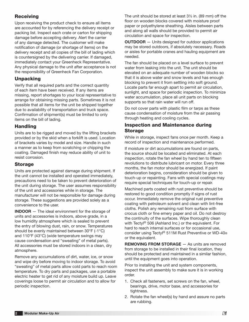
Installation, Operation and Maintenance ManualPlease read and save these instructions for future reference. Read carefully before attempting to assemble, install, operate or maintain the product described. Protect yourself and others by observing all safety information. Failure to comply with instructions could result in personal injury and/or property damage!
Modular Make-Up Air 1®
DANGERAlways disconnect power before working on or near a unit. Lock and tag the disconnect switch or breaker to prevent accidental power up.
CAUTIONWhen servicing the unit, motor may be hot enough to cause pain or injury. Allow motor to cool before servicing.
IMPORTANTAll factory provided lifting lugs must be used when lifting any unit. Failure to comply with this safety precaution could result in property damage, serious injury or death.
WARNINGDisconnect all electrical power to the fan and secure to the “OFF” position prior to inspection or servicing. Failure to comply with this safety precaution could result in serious injury or death.
WARNINGImproper installation, adjustment, alteration, service or maintenance can cause property damage, injury or death. Read the installation, operating and maintenance instructions thoroughly before installing or servicing this equipment.
General Safety InformationOnly qualified personnel should install this unit. Personnel should have a clear understanding of these instructions and should be aware of general safety precautions. Improper installation can result in electric shock, possible injury due to coming in contact with moving parts, as well as other potential hazards. Other considerations may be required if high winds or seismic activity are present. If more information is needed, contact a licensed professional engineer before moving forward.
1. Follow all local electrical and safety codes, as well as the National Electrical Code (NEC), the National Fire Protection Agency (NFPA), where applicable. Follow the Canadian Electrical Code (CEC) in Canada.
2. The rotation of the wheel is critical. It must be free to rotate without striking or rubbing any stationary objects.
3. Motor must be securely and adequately grounded.4. Do not spin fan wheel faster than maximum
cataloged fan rpm. Adjustments to fan speed significantly effects motor load. If the fan RPM is changed, the motor current should be checked to make sure it is not exceeding the motor nameplate amps.
5. Do not allow the power cable to kink or come in contact with oil, grease, hot surfaces, or chemicals. Replace cord immediately if damaged.
6. Verify that the power source is compatible with the equipment.
7. Never open blower access doors while the fan is running.
Modular Make-Up Air2®
The unit should be stored at least 3½ in. (89 mm) off the floor on wooden blocks covered with moisture proof paper or polyethylene sheathing. Aisles between parts and along all walls should be provided to permit air circulation and space for inspection.
OUTDOOR — Units designed for outdoor applications may be stored outdoors, if absolutely necessary. Roads or aisles for portable cranes and hauling equipment are needed.
The fan should be placed on a level surface to prevent water from leaking into the unit. The unit should be elevated on an adequate number of wooden blocks so that it is above water and snow levels and has enough blocking to prevent it from settling into soft ground. Locate parts far enough apart to permit air circulation, sunlight, and space for periodic inspection. To minimize water accumulation, place all unit parts on blocking supports so that rain water will run off.
Do not cover parts with plastic film or tarps as these cause condensation of moisture from the air passing through heating and cooling cycles.
Inspection and Maintenance during StorageWhile in storage, inspect fans once per month. Keep a record of inspection and maintenance performed.
If moisture or dirt accumulations are found on parts, the source should be located and eliminated. At each inspection, rotate the fan wheel by hand ten to fifteen revolutions to distribute lubricant on motor. Every three months, the fan motor should be energized. If paint deterioration begins, consideration should be given to touch-up or repainting. Fans with special coatings may require special techniques for touch-up or repair.
Machined parts coated with rust preventive should be restored to good condition promptly if signs of rust occur. Immediately remove the original rust preventive coating with petroleum solvent and clean with lint-free cloths. Polish any remaining rust from surface with crocus cloth or fine emery paper and oil. Do not destroy the continuity of the surfaces. Wipe thoroughly clean with Tectyl® 506 (Ashland Inc.) or the equivalent. For hard to reach internal surfaces or for occasional use, consider using Tectyl® 511M Rust Preventive or WD-40® or the equivalent.
REMOVING FROM STORAGE — As units are removed from storage to be installed in their final location, they should be protected and maintained in a similar fashion, until the equipment goes into operation.
Prior to installing the unit and system components, inspect the unit assembly to make sure it is in working order.
1. Check all fasteners, set screws on the fan, wheel, bearings, drive, motor base, and accessories for tightness.
2. Rotate the fan wheel(s) by hand and assure no parts are rubbing.
ReceivingUpon receiving the product check to ensure all items are accounted for by referencing the delivery receipt or packing list. Inspect each crate or carton for shipping damage before accepting delivery. Alert the carrier of any damage detected. The customer will make notification of damage (or shortage of items) on the delivery receipt and all copies of the bill of lading which is countersigned by the delivering carrier. If damaged, immediately contact your Greenheck Representative. Any physical damage to the unit after acceptance is not the responsibility of Greenheck Fan Corporation.
UnpackingVerify that all required parts and the correct quantity of each item have been received. If any items are missing, report shortages to your local representative to arrange for obtaining missing parts. Sometimes it is not possible that all items for the unit be shipped together due to availability of transportation and truck space. Confirmation of shipment(s) must be limited to only items on the bill of lading.
HandlingUnits are to be rigged and moved by the lifting brackets provided or by the skid when a forklift is used. Location of brackets varies by model and size. Handle in such a manner as to keep from scratching or chipping the coating. Damaged finish may reduce ability of unit to resist corrosion.
StorageUnits are protected against damage during shipment. If the unit cannot be installed and operated immediately, precautions need to be taken to prevent deterioration of the unit during storage. The user assumes responsibility of the unit and accessories while in storage. The manufacturer will not be responsible for damage during storage. These suggestions are provided solely as a convenience to the user.
INDOOR — The ideal environment for the storage of units and accessories is indoors, above grade, in a low humidity atmosphere which is sealed to prevent the entry of blowing dust, rain, or snow. Temperatures should be evenly maintained between 30°F (-1°C) and 110°F (43°C) (wide temperature swings may cause condensation and “sweating” of metal parts). All accessories must be stored indoors in a clean, dry atmosphere.
Remove any accumulations of dirt, water, ice, or snow and wipe dry before moving to indoor storage. To avoid “sweating” of metal parts allow cold parts to reach room temperature. To dry parts and packages, use a portable electric heater to get rid of any moisture build up. Leave coverings loose to permit air circulation and to allow for periodic inspection.
Modular Make-Up Air 3®
Table of ContentsInstallation
Clearance to Combustibles/Service Clearances . . 4Indoor Unit . . . . . . . . . . . . . . . . . . . . . . . . . . . . . . . 4Unit Arrangement DB / HZ / UB . . . . . . . . . . . . . . 4Roof Mounted Unit — Arrangement DBC . . . . . .5-6Optional Evaporative Cooling Module . . . . . . . . . . 7Electrical Wiring . . . . . . . . . . . . . . . . . . . . . . . . . . . 8Optional Electrical Heater . . . . . . . . . . . . . . . . . . . 9Optional Evaporative Cooling Piping . . . . . . . .10-11Optional Water Wizard™ . . . . . . . . . . . . . . . . . . . 12Optional Direct Expansion (DX) Coil Piping . . .13-14Optional Chilled Water Coil Piping . . . . . . . . . . . 15Optional Building Pressure Control . . . . . . . . . . . 15
Start-Up
Start-Up Checklist . . . . . . . . . . . . . . . . . . . . . . . . 16Blower . . . . . . . . . . . . . . . . . . . . . . . . . . . . . . . . . 17Optional Electric Heater . . . . . . . . . . . . . . . . . . . . 18Optional Economizer . . . . . . . . . . . . . . . . . . . . . . 19Optional Evaporative Cooling Recirculating . . . . 20Optional Water Wizard™ . . . . . . . . . . . . . . . . .21-22Optional Microprocessor Controller . . . . . . . . . . . 22
Operation
Optional VAV Units . . . . . . . . . . . . . . . . . . . . . . . . 23Optional Recirculating Units . . . . . . . . . . . . . . . . 24Electrical . . . . . . . . . . . . . . . . . . . . . . . . . . . . . . . . 25Optional Water Wizard™ . . . . . . . . . . . . . . . . . . . 26
Troubleshooting
Blower . . . . . . . . . . . . . . . . . . . . . . . . . . . . . . . . . 27Motor Overamps . . . . . . . . . . . . . . . . . . . . . . . . . 28Insufficient / Too Much Airflow . . . . . . . . . . . . . . 29Excessive Noise or Vibration . . . . . . . . . . . . . . . . 30Optional Electric Heater . . . . . . . . . . . . . . . . . . . . 31Optional Evaporative Cooling . . . . . . . . . . . . . . . 32Optional Water Wizard™ . . . . . . . . . . . . . . . . . . . 33
Maintenance
Routine . . . . . . . . . . . . . . . . . . . . . . . . . . . . . . .34-36Fall . . . . . . . . . . . . . . . . . . . . . . . . . . . . . . . . . . . . 36
Reference
Control Center Layout / Dirty Filter Switch . . . . . 37Maintenance Log . . . . . . . . . . . . . . . . . . . . . . .38-39Our Commitment . . . . . . . . . . . . . . . . . . . Backcover
Modular Make-Up Air4®
NOTETwo nuts must be used on each end of each threaded hanging rod for proper support.
NOTEGood duct practices should be followed for all ductwork. Ductwork should be installed in accordance with SMACNA and AMCA guidelines, NFPA 96 and any local codes. Reference the CAPS submittal for duct sizes.
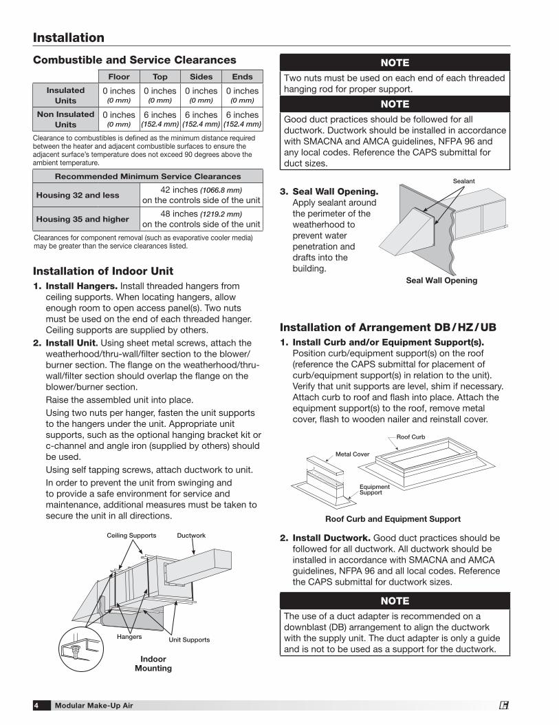
3. Seal Wall Opening. Apply sealant around the perimeter of the weatherhood to prevent water penetration and drafts into the building.
Sealant
Seal Wall Opening
Combustible and Service Clearances
Installation
Floor Top Sides Ends
Insulated
Units
0 inches(0 mm)
0 inches(0 mm)
0 inches(0 mm)
0 inches(0 mm)
Non Insulated
Units
0 inches (0 mm)
6 inches (152.4 mm)
6 inches (152.4 mm)
6 inches (152.4 mm)
Clearance to combustibles is defined as the minimum distance required between the heater and adjacent combustible surfaces to ensure the adjacent surface’s temperature does not exceed 90 degrees above the ambient temperature.
Recommended Minimum Service Clearances
Housing 32 and less42 inches (1066.8 mm)
on the controls side of the unit
Housing 35 and higher48 inches (1219.2 mm)
on the controls side of the unit
Clearances for component removal (such as evaporative cooler media) may be greater than the service clearances listed.
Installation of Indoor Unit1. Install Hangers. Install threaded hangers from
ceiling supports. When locating hangers, allow enough room to open access panel(s). Two nuts must be used on the end of each threaded hanger. Ceiling supports are supplied by others.
2. Install Unit. Using sheet metal screws, attach the weatherhood/thru-wall/filter section to the blower/burner section. The flange on the weatherhood/thru-wall/filter section should overlap the flange on the blower/burner section.
Raise the assembled unit into place. Using two nuts per hanger, fasten the unit supports
to the hangers under the unit. Appropriate unit supports, such as the optional hanging bracket kit or c-channel and angle iron (supplied by others) should be used.
Using self tapping screws, attach ductwork to unit. In order to prevent the unit from swinging and
to provide a safe environment for service and maintenance, additional measures must be taken to secure the unit in all directions.
Unit Supports
Ceiling Supports
Hangers
Ductwork
Indoor Mounting
NOTEThe use of a duct adapter is recommended on a downblast (DB) arrangement to align the ductwork with the supply unit. The duct adapter is only a guide and is not to be used as a support for the ductwork.
Installation of Arrangement DB / HZ / UB1. Install Curb and/or Equipment Support(s).
Position curb/equipment support(s) on the roof (reference the CAPS submittal for placement of curb/equipment support(s) in relation to the unit). Verify that unit supports are level, shim if necessary. Attach curb to roof and flash into place. Attach the equipment support(s) to the roof, remove metal cover, flash to wooden nailer and reinstall cover.
Metal Cover
EquipmentSupport
Roof Curb
Roof Curb and Equipment Support
2. Install Ductwork. Good duct practices should be followed for all ductwork. All ductwork should be installed in accordance with SMACNA and AMCA guidelines, NFPA 96 and all local codes. Reference the CAPS submittal for ductwork sizes.
Modular Make-Up Air 5®
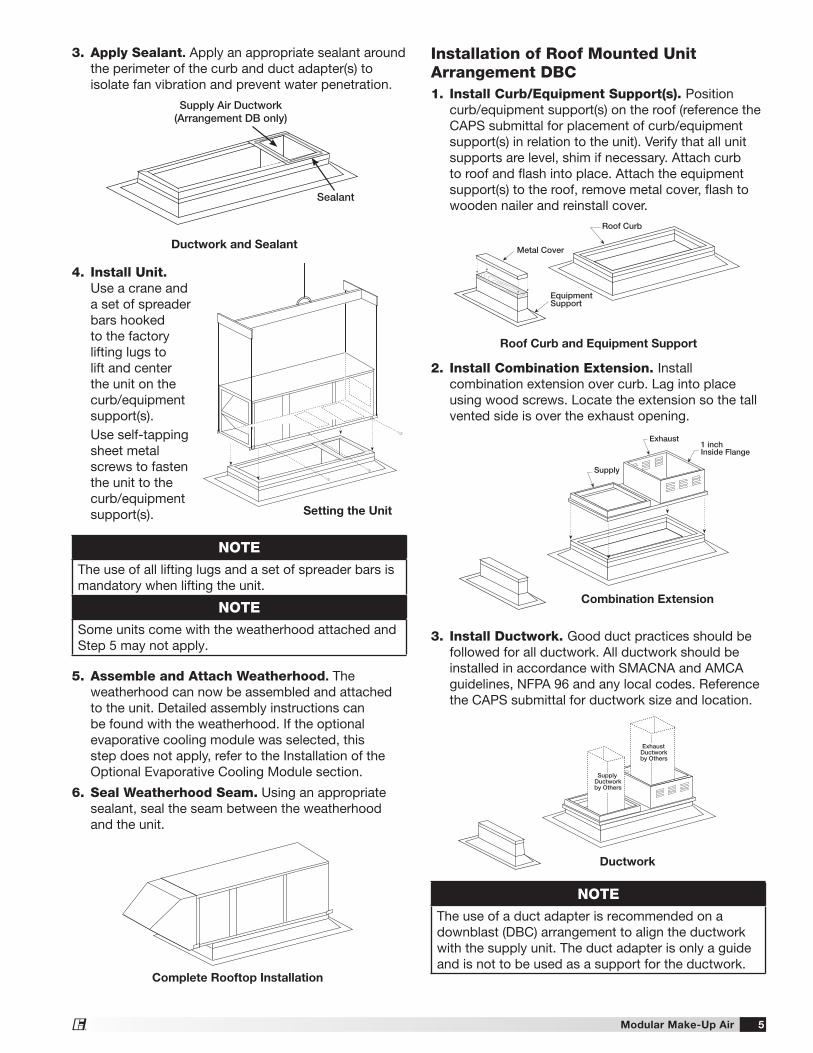
Installation of Roof Mounted Unit Arrangement DBC1. Install Curb/Equipment Support(s). Position
curb/equipment support(s) on the roof (reference the CAPS submittal for placement of curb/equipment support(s) in relation to the unit). Verify that all unit supports are level, shim if necessary. Attach curb to roof and flash into place. Attach the equipment support(s) to the roof, remove metal cover, flash to wooden nailer and reinstall cover.
2. Install Combination Extension. Install combination extension over curb. Lag into place using wood screws. Locate the extension so the tall vented side is over the exhaust opening.
3. Install Ductwork. Good duct practices should be followed for all ductwork. All ductwork should be installed in accordance with SMACNA and AMCA guidelines, NFPA 96 and any local codes. Reference the CAPS submittal for ductwork size and location.
SupplyDuctworkby Others
ExhaustDuctworkby Others
NOTEThe use of a duct adapter is recommended on a downblast (DBC) arrangement to align the ductwork with the supply unit. The duct adapter is only a guide and is not to be used as a support for the ductwork.
Metal Cover
EquipmentSupport
Roof Curb
Roof Curb and Equipment Support
Exhaust
Supply
1 inchInside Flange
Combination Extension
Ductwork
3. Apply Sealant. Apply an appropriate sealant around the perimeter of the curb and duct adapter(s) to isolate fan vibration and prevent water penetration.
Supply Air Ductwork (Arrangement DB only)
Sealant
Ductwork and Sealant
NOTEThe use of all lifting lugs and a set of spreader bars is mandatory when lifting the unit.
NOTESome units come with the weatherhood attached and Step 5 may not apply.
4. Install Unit. Use a crane and a set of spreader bars hooked to the factory lifting lugs to lift and center the unit on the curb/equipment support(s).
Use self-tapping sheet metal screws to fasten the unit to the curb/equipment support(s). Setting the Unit
5. Assemble and Attach Weatherhood. The weatherhood can now be assembled and attached to the unit. Detailed assembly instructions can be found with the weatherhood. If the optional evaporative cooling module was selected, this step does not apply, refer to the Installation of the Optional Evaporative Cooling Module section.
6. Seal Weatherhood Seam. Using an appropriate sealant, seal the seam between the weatherhood and the unit.
Complete Rooftop Installation
Modular Make-Up Air6®
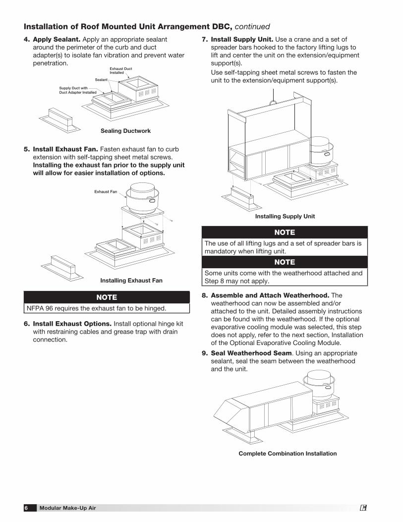
7. Install Supply Unit. Use a crane and a set of spreader bars hooked to the factory lifting lugs to lift and center the unit on the extension/equipment support(s).
Use self-tapping sheet metal screws to fasten the unit to the extension/equipment support(s).
8. Assemble and Attach Weatherhood. The weatherhood can now be assembled and/or attached to the unit. Detailed assembly instructions can be found with the weatherhood. If the optional evaporative cooling module was selected, this step does not apply, refer to the next section, Installation of the Optional Evaporative Cooling Module.
9. Seal Weatherhood Seam. Using an appropriate sealant, seal the seam between the weatherhood and the unit.
NOTEThe use of all lifting lugs and a set of spreader bars is mandatory when lifting unit.
NOTESome units come with the weatherhood attached and Step 8 may not apply.
Installing Supply Unit
Complete Combination Installation
6. Install Exhaust Options. Install optional hinge kit with restraining cables and grease trap with drain connection.
5. Install Exhaust Fan. Fasten exhaust fan to curb extension with self-tapping sheet metal screws. Installing the exhaust fan prior to the supply unit
will allow for easier installation of options.
4. Apply Sealant. Apply an appropriate sealant around the perimeter of the curb and duct adapter(s) to isolate fan vibration and prevent water penetration.
NOTENFPA 96 requires the exhaust fan to be hinged.
Supply Duct withDuct Adapter Installed
Exhaust DuctInstalled
Sealant
Sealing Ductwork
Exhaust Fan
Installing Exhaust Fan
Installation of Roof Mounted Unit Arrangement DBC, continued
Modular Make-Up Air 7®
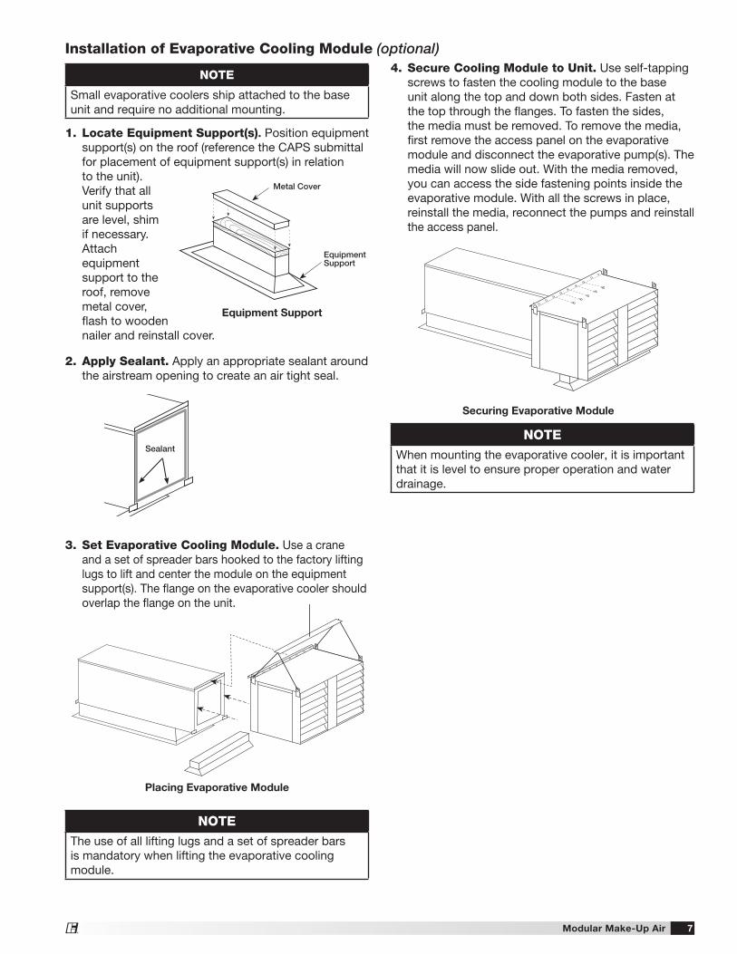
Installation of Evaporative Cooling Module (optional)
NOTE
Small evaporative coolers ship attached to the base unit and require no additional mounting.
NOTEThe use of all lifting lugs and a set of spreader bars is mandatory when lifting the evaporative cooling module.
NOTEWhen mounting the evaporative cooler, it is important that it is level to ensure proper operation and water drainage.
Placing Evaporative Module
Securing Evaporative Module
1. Locate Equipment Support(s). Position equipment support(s) on the roof (reference the CAPS submittal for placement of equipment support(s) in relation to the unit). Verify that all unit supports are level, shim if necessary. Attach equipment support to the roof, remove metal cover, flash to wooden nailer and reinstall cover.
4. Secure Cooling Module to Unit. Use self-tapping screws to fasten the cooling module to the base unit along the top and down both sides. Fasten at the top through the flanges. To fasten the sides, the media must be removed. To remove the media, first remove the access panel on the evaporative module and disconnect the evaporative pump(s). The media will now slide out. With the media removed, you can access the side fastening points inside the evaporative module. With all the screws in place, reinstall the media, reconnect the pumps and reinstall the access panel.
Sealant
3. Set Evaporative Cooling Module. Use a crane and a set of spreader bars hooked to the factory lifting lugs to lift and center the module on the equipment support(s). The flange on the evaporative cooler should overlap the flange on the unit.
2. Apply Sealant. Apply an appropriate sealant around the airstream opening to create an air tight seal.
Metal Cover
EquipmentSupport
Equipment Support
Modular Make-Up Air8®
Installation of Electrical Wiring
IMPORTANTBefore connecting power to the unit, read and understand the following instructions and wiring diagrams. Complete wiring diagrams are attached on the inside of the control center door(s).
IMPORTANTAll wiring should be done in accordance with the latest edition of the wal Code ANSI/NFPA 70 and any local codes that may apply. In Canada, wiring should be done in accordance with the Canadian Electrical Code.
IMPORTANTThe equipment must be properly grounded. Any wiring running through the unit in the airstream must be protected by metal conduit, metal clad cable or raceways.
CAUTIONIf replacement wire is required, it must have a temperature rating of at least 105°C, except for an energy cut-off or sensor lead wire which must be rated to 150°C.
DANGERHigh voltage electrical input is needed for this equipment. This work should be performed by a qualified electrician.
CAUTIONAny wiring deviations may result in personal injury or property damage. Manufacturer is not responsible for any damage to, or failure of the unit caused by incorrect final wiring.
IMPORTANTManufacturer’s standard control voltage is 24 VAC. Control wire resistance should not exceed 0.75 ohms (approximately 285 feet total length for 14 gauge wire; 455 feet total length for 12 gauge wire). If the resistance exceeds 0.75 ohms, an industrial-style plug-in relay should be wired in place of the remote switch. The relay must be rated for at least 5 amps and have a 24 VAC coil. Failure to comply with these guidelines may cause motor starters to chatter or not pull in, resulting in contactor failures and/or motor failures.
1. Determine the Size of the Main Power Lines. The unit’s nameplate states the voltage and the unit’s MCA. The main power lines to the unit should be sized accordingly. The nameplate is located on the outside of the unit on the control panel side.
2. Provide the Opening(s) for the Electrical Connection. Electrical openings vary by unit size and arrangement and are field-supplied.
3. Connect the Main Power. Connect the main power lines to the disconnect switch and main grounding lug(s). Torque field connections to 20 in.-lbs.
4. Wire the Optional Convenience Outlet. The convenience outlet requires a separate 115 volt power supply circuit. The circuit must include short circuit protection which may need to be supplied by others.
5. Wire the Optional Accessories. Reference the Ladder Diagram on the inside of the control center door for correct wiring of the following accessories:• Blower Switch• Heat Switch• Indicating Lights
• Dirty Filter Indicator• TSCP• KSCP
NOTETSCP has number-to-number wiring.
NOTELarge evaporative coolers may require a separate power supply.
6. Wire the Optional Evaporative Cooler. Reference the Ladder Diagram on the inside of the control center door for correct wiring of the pump and the optional auto-drain and flush.
Modular Make-Up Air 9®
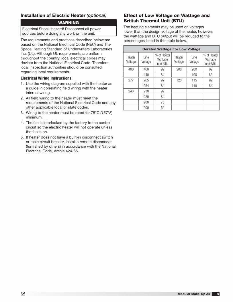
Effect of Low Voltage on Wattage and British Thermal Unit (BTU)The heating elements may be used on voltages lower than the design voltage of the heater, however, the wattage and BTU output will be reduced to the percentages listed in the table below.
Installation of Electric Heater (optional)
The requirements and practices described below are based on the National Electrical Code (NEC) and The Space Heating Standard of Underwriters Laboratories Inc. (UL). Although UL requirements are uniform throughout the country, local electrical codes may deviate from the National Electrical Code. Therefore, local inspection authorities should be consulted regarding local requirements.
Electrical Wiring Instructions1. Use the wiring diagram supplied with the heater as
a guide in correlating field wiring with the heater internal wiring.
2. All field wiring to the heater must meet the requirements of the National Electrical Code and any other applicable local or state codes.
3. Wiring to the heater must be rated for 75°C (167°F) minimum.
4. The fan is interlocked by the factory to the control circuit so the electric heater will not operate unless the fan is on.
5. If heater does not have a built-in disconnect switch or main circuit breaker, install a remote disconnect (furnished by others) in accordance with the National Electrical Code, Article 424-65.
Derated Wattage For Low Voltage
Heater
Voltage
Line
Voltage
% of Heater
Wattage
and BTU
Heater
Voltage
Line
Voltage
% of Heater
Wattage
and BTU
480 460 92 208 200 92
440 84 190 83
277 265 92 120 115 92
254 84 110 84
240 230 92
220 84
208 75
200 69
WARNINGElectrical Shock Hazard! Disconnect all power sources before doing any work on the unit.
Modular Make-Up Air10®
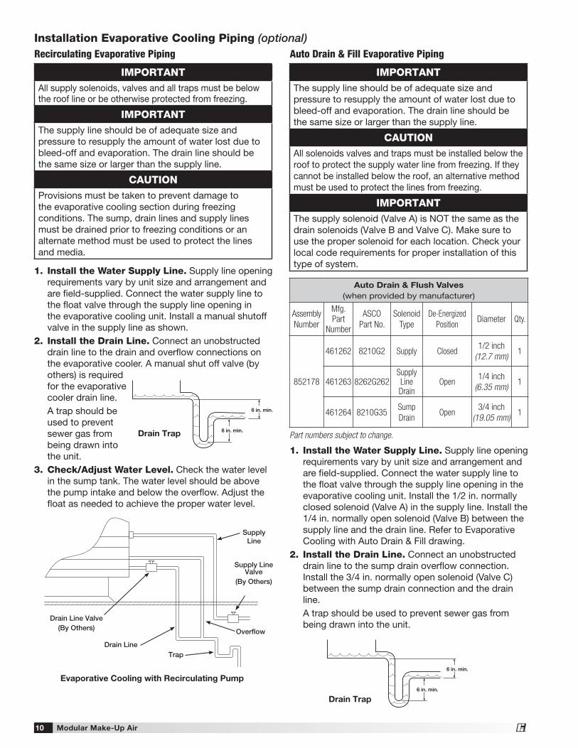
Installation Evaporative Cooling Piping (optional)Recirculating Evaporative Piping
IMPORTANTAll supply solenoids, valves and all traps must be below the roof line or be otherwise protected from freezing.
IMPORTANTThe supply line should be of adequate size and pressure to resupply the amount of water lost due to bleed-off and evaporation. The drain line should be the same size or larger than the supply line.
CAUTIONProvisions must be taken to prevent damage to the evaporative cooling section during freezing conditions. The sump, drain lines and supply lines must be drained prior to freezing conditions or an alternate method must be used to protect the lines and media.
1. Install the Water Supply Line. Supply line opening requirements vary by unit size and arrangement and are field-supplied. Connect the water supply line to the float valve through the supply line opening in the evaporative cooling unit. Install a manual shutoff valve in the supply line as shown.
2. Install the Drain Line. Connect an unobstructed drain line to the drain and overflow connections on the evaporative cooler. A manual shut off valve (by others) is required for the evaporative cooler drain line.
A trap should be used to prevent sewer gas from being drawn into the unit.
3. Check/Adjust Water Level. Check the water level in the sump tank. The water level should be above the pump intake and below the overflow. Adjust the float as needed to achieve the proper water level.
Evaporative Cooling with Recirculating Pump
Supply Line
Overflow
Trap
Drain Line Valve(By Others)
Drain Line
Supply Line Valve
(By Others)
6 in. min.
6 in. min.
Drain Trap
Auto Drain & Flush Valves
(when provided by manufacturer)
Assembly
Number
Mfg.
Part
Number
ASCO
Part No.
Solenoid
Type
De-Energized
PositionDiameter Qty.
852178
461262 8210G2 Supply Closed1/2 inch
(12.7 mm)1
461263 8262G262Supply Line Drain
Open1/4 inch
(6.35 mm)1
461264 8210G35Sump
DrainOpen
3/4 inch
(19.05 mm)1
Part numbers subject to change.
IMPORTANTThe supply line should be of adequate size and pressure to resupply the amount of water lost due to bleed-off and evaporation. The drain line should be the same size or larger than the supply line.
CAUTIONAll solenoids valves and traps must be installed below the roof to protect the supply water line from freezing. If they cannot be installed below the roof, an alternative method must be used to protect the lines from freezing.
IMPORTANTThe supply solenoid (Valve A) is NOT the same as the drain solenoids (Valve B and Valve C). Make sure to use the proper solenoid for each location. Check your local code requirements for proper installation of this type of system.
Auto Drain & Fill Evaporative Piping
1. Install the Water Supply Line. Supply line opening requirements vary by unit size and arrangement and are field-supplied. Connect the water supply line to the float valve through the supply line opening in the evaporative cooling unit. Install the 1/2 in. normally closed solenoid (Valve A) in the supply line. Install the 1/4 in. normally open solenoid (Valve B) between the supply line and the drain line. Refer to Evaporative Cooling with Auto Drain & Fill drawing.
2. Install the Drain Line. Connect an unobstructed drain line to the sump drain overflow connection. Install the 3/4 in. normally open solenoid (Valve C) between the sump drain connection and the drain line.
A trap should be used to prevent sewer gas from being drawn into the unit.
6 in. min.
6 in. min.
Drain Trap
Modular Make-Up Air 11®
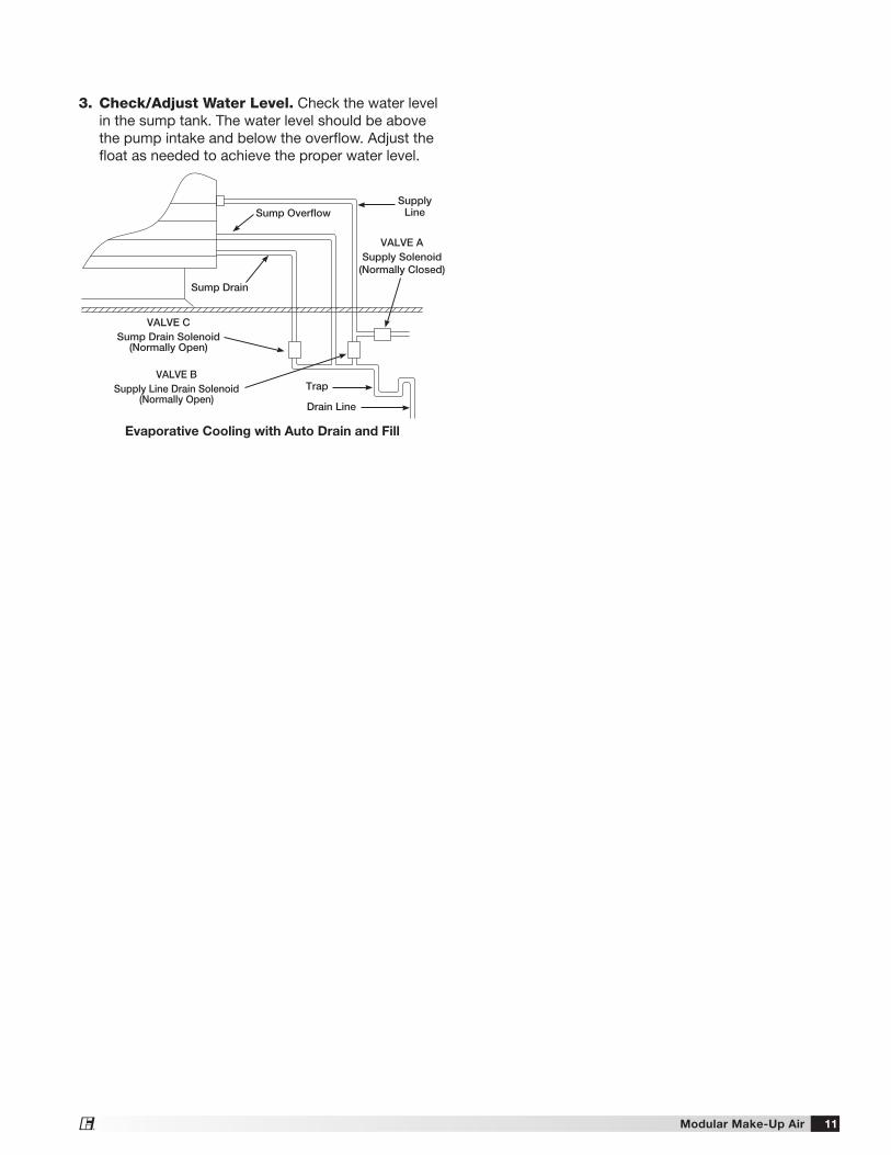
Evaporative Cooling with Auto Drain and Fill
Supply Line
VALVE BSupply Line Drain Solenoid
(Normally Open)
Sump Overflow
Sump Drain
VALVE CSump Drain Solenoid
(Normally Open)
VALVE ASupply Solenoid
(Normally Closed)
Drain Line
Trap
3. Check/Adjust Water Level. Check the water level in the sump tank. The water level should be above the pump intake and below the overflow. Adjust the float as needed to achieve the proper water level.
Modular Make-Up Air12®
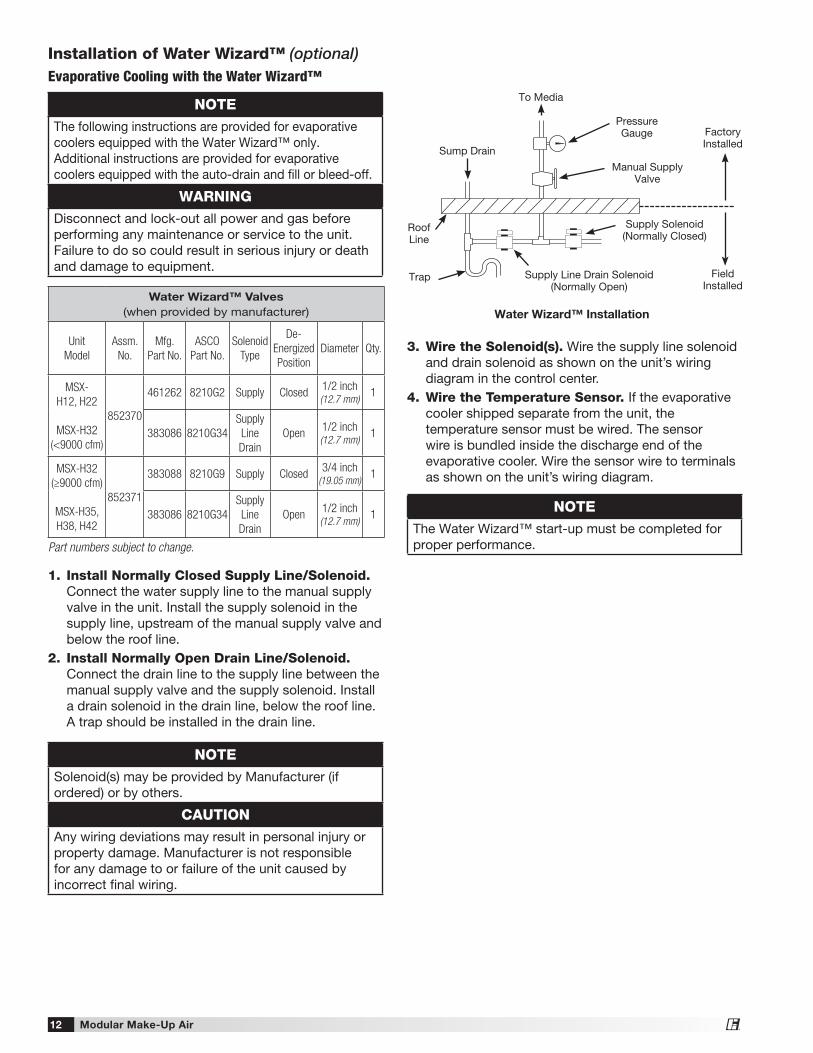
Installation of Water Wizard™ (optional)Evaporative Cooling with the Water Wizard™
1. Install Normally Closed Supply Line/Solenoid. Connect the water supply line to the manual supply valve in the unit. Install the supply solenoid in the supply line, upstream of the manual supply valve and below the roof line.
2. Install Normally Open Drain Line/Solenoid. Connect the drain line to the supply line between the manual supply valve and the supply solenoid. Install a drain solenoid in the drain line, below the roof line. A trap should be installed in the drain line.
3. Wire the Solenoid(s). Wire the supply line solenoid and drain solenoid as shown on the unit’s wiring diagram in the control center.
4. Wire the Temperature Sensor. If the evaporative cooler shipped separate from the unit, the temperature sensor must be wired. The sensor wire is bundled inside the discharge end of the evaporative cooler. Wire the sensor wire to terminals as shown on the unit’s wiring diagram.
NOTEThe following instructions are provided for evaporative coolers equipped with the Water Wizard™ only. Additional instructions are provided for evaporative coolers equipped with the auto-drain and fill or bleed-off.
WARNINGDisconnect and lock-out all power and gas before performing any maintenance or service to the unit. Failure to do so could result in serious injury or death and damage to equipment.
NOTESolenoid(s) may be provided by Manufacturer (if ordered) or by others.
CAUTIONAny wiring deviations may result in personal injury or property damage. Manufacturer is not responsible for any damage to or failure of the unit caused by incorrect final wiring.
NOTEThe Water Wizard™ start-up must be completed for proper performance.
Water Wizard™ Valves
(when provided by manufacturer)
Unit
Model
Assm.
No.
Mfg.
Part No.
ASCO
Part No.
Solenoid
Type
De-
Energized
Position
Diameter Qty.
MSX-
H12, H22
MSX-H32
(<9000 cfm)
852370
461262 8210G2 Supply Closed1/2 inch (12.7 mm)
1
383086 8210G34
Supply
Line
Drain
Open1/2 inch (12.7 mm)
1
MSX-H32
(≥9000 cfm)
MSX-H35,
H38, H42
852371
383088 8210G9 Supply Closed3/4 inch
(19.05 mm)1
383086 8210G34
Supply
Line
Drain
Open1/2 inch(12.7 mm)
1
Part numbers subject to change.
Water Wizard™ Installation
Supply Line Drain Solenoid(Normally Open)
Supply Solenoid(Normally Closed)
Manual Supply Valve
PressureGauge
To Media
Sump Drain
Roof Line
Trap Field Installed
Factory Installed
Modular Make-Up Air 13®
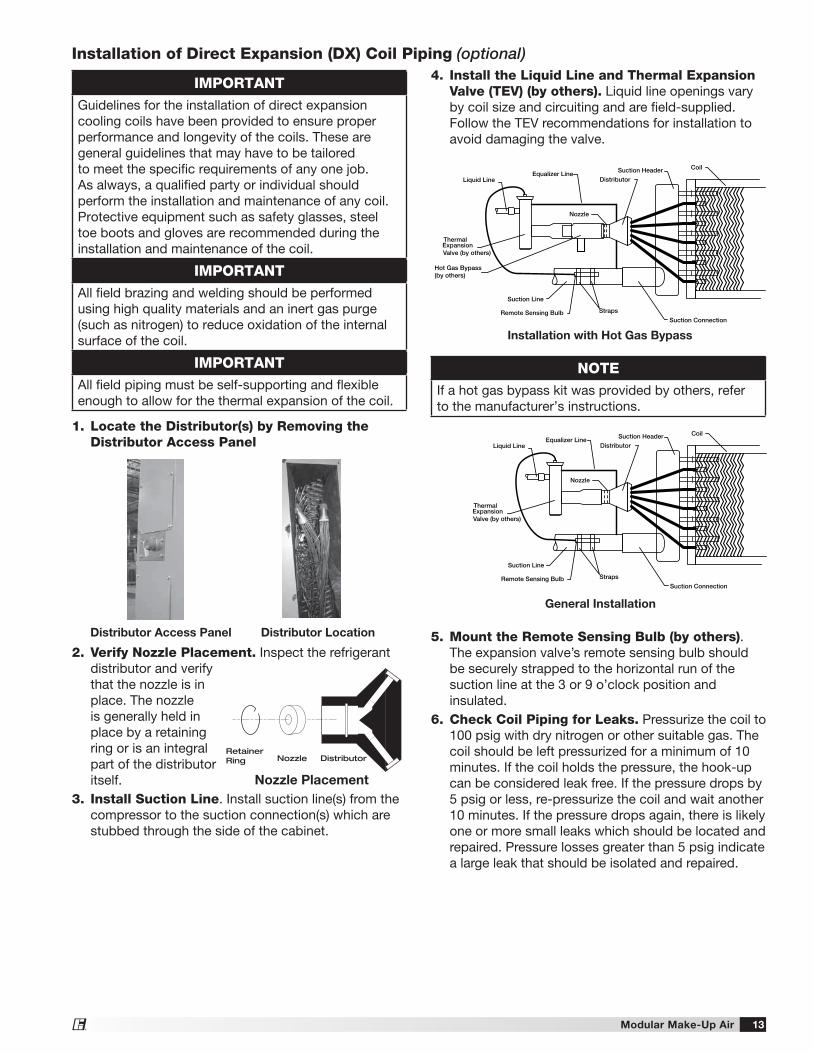
4. Install the Liquid Line and Thermal Expansion Valve (TEV) (by others). Liquid line openings vary by coil size and circuiting and are field-supplied. Follow the TEV recommendations for installation to avoid damaging the valve.
5. Mount the Remote Sensing Bulb (by others). The expansion valve’s remote sensing bulb should be securely strapped to the horizontal run of the suction line at the 3 or 9 o’clock position and insulated.
6. Check Coil Piping for Leaks. Pressurize the coil to 100 psig with dry nitrogen or other suitable gas. The coil should be left pressurized for a minimum of 10 minutes. If the coil holds the pressure, the hook-up can be considered leak free. If the pressure drops by 5 psig or less, re-pressurize the coil and wait another 10 minutes. If the pressure drops again, there is likely one or more small leaks which should be located and repaired. Pressure losses greater than 5 psig indicate a large leak that should be isolated and repaired.
1. Locate the Distributor(s) by Removing the Distributor Access Panel
2. Verify Nozzle Placement. Inspect the refrigerant distributor and verify that the nozzle is in place. The nozzle is generally held in place by a retaining ring or is an integral part of the distributor itself.
3. Install Suction Line. Install suction line(s) from the compressor to the suction connection(s) which are stubbed through the side of the cabinet.
RetainerRing Nozzle Distributor
Nozzle Placement
Distributor Access Panel Distributor Location
NOTEIf a hot gas bypass kit was provided by others, refer to the manufacturer’s instructions.
General Installation
Expansion Valve (by others)
Liquid Line
Thermal
Nozzle
Suction Header Coil
Distributor
Suction Line
Remote Sensing Bulb Straps
Suction Connection
Equalizer Line
Expansion Valve (by others)
Liquid Line
Thermal
Nozzle
Suction Header Coil
Distributor
Suction Line
Remote Sensing Bulb Straps
Suction Connection
Hot Gas Bypass (by others)
Equalizer Line
Installation with Hot Gas Bypass
IMPORTANTGuidelines for the installation of direct expansion cooling coils have been provided to ensure proper performance and longevity of the coils. These are general guidelines that may have to be tailored to meet the specific requirements of any one job. As always, a qualified party or individual should perform the installation and maintenance of any coil. Protective equipment such as safety glasses, steel toe boots and gloves are recommended during the installation and maintenance of the coil.
IMPORTANTAll field brazing and welding should be performed using high quality materials and an inert gas purge (such as nitrogen) to reduce oxidation of the internal surface of the coil.
IMPORTANTAll field piping must be self-supporting and flexible enough to allow for the thermal expansion of the coil.
Installation of Direct Expansion (DX) Coil Piping (optional)
Modular Make-Up Air14®
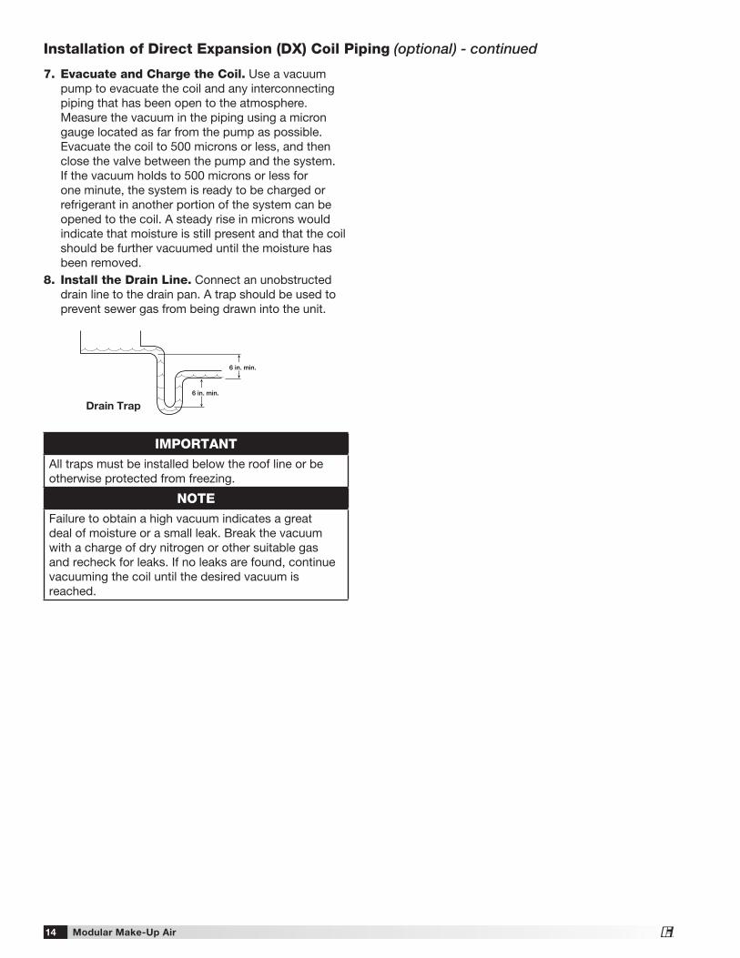
7. Evacuate and Charge the Coil. Use a vacuum pump to evacuate the coil and any interconnecting piping that has been open to the atmosphere. Measure the vacuum in the piping using a micron gauge located as far from the pump as possible. Evacuate the coil to 500 microns or less, and then close the valve between the pump and the system. If the vacuum holds to 500 microns or less for one minute, the system is ready to be charged or refrigerant in another portion of the system can be opened to the coil. A steady rise in microns would indicate that moisture is still present and that the coil should be further vacuumed until the moisture has been removed.
8. Install the Drain Line. Connect an unobstructed drain line to the drain pan. A trap should be used to prevent sewer gas from being drawn into the unit.
6 in. min.
6 in. min.
Drain Trap
IMPORTANTAll traps must be installed below the roof line or be otherwise protected from freezing.
NOTEFailure to obtain a high vacuum indicates a great deal of moisture or a small leak. Break the vacuum with a charge of dry nitrogen or other suitable gas and recheck for leaks. If no leaks are found, continue vacuuming the coil until the desired vacuum is reached.
Installation of Direct Expansion (DX) Coil Piping (optional) - continued
Modular Make-Up Air 15®
IMPORTANTAll traps must be installed below the roof line or be otherwise protected from freezing.
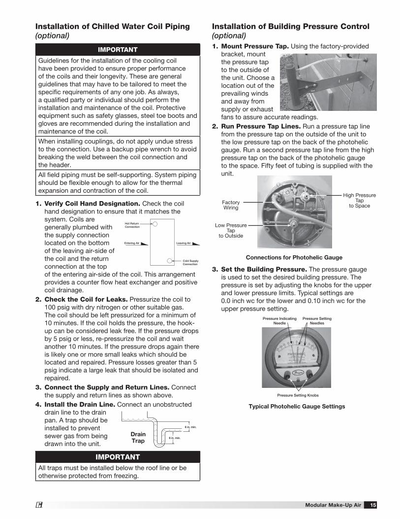
Installation of Building Pressure Control (optional)1. Mount Pressure Tap. Using the factory-provided
bracket, mount the pressure tap to the outside of the unit. Choose a location out of the prevailing winds and away from supply or exhaust fans to assure accurate readings.
2. Run Pressure Tap Lines. Run a pressure tap line from the pressure tap on the outside of the unit to the low pressure tap on the back of the photohelic gauge. Run a second pressure tap line from the high pressure tap on the back of the photohelic gauge to the space. Fifty feet of tubing is supplied with the unit.
3. Set the Building Pressure. The pressure gauge is used to set the desired building pressure. The pressure is set by adjusting the knobs for the upper and lower pressure limits. Typical settings are 0.0 inch wc for the lower and 0.10 inch wc for the upper pressure setting.
Connections for Photohelic Gauge
Factory Wiring
High Pressure Tap
to Space
Low Pressure Tap
to Outside
Typical Photohelic Gauge Settings
Pressure Setting Knobs
Pressure Setting Needles
Pressure Indicating Needle
Installation of Chilled Water Coil Piping (optional)
1. Verify Coil Hand Designation. Check the coil hand designation to ensure that it matches the system. Coils are generally plumbed with the supply connection located on the bottom of the leaving air-side of the coil and the return connection at the top of the entering air-side of the coil. This arrangement provides a counter flow heat exchanger and positive coil drainage.
2. Check the Coil for Leaks. Pressurize the coil to 100 psig with dry nitrogen or other suitable gas. The coil should be left pressurized for a minimum of 10 minutes. If the coil holds the pressure, the hook-up can be considered leak free. If the pressure drops by 5 psig or less, re-pressurize the coil and wait another 10 minutes. If the pressure drops again there is likely one or more small leaks which should be located and repaired. Pressure losses greater than 5 psig indicate a large leak that should be isolated and repaired.
3. Connect the Supply and Return Lines. Connect the supply and return lines as shown above.
4. Install the Drain Line. Connect an unobstructed drain line to the drain pan. A trap should be installed to prevent sewer gas from being drawn into the unit.
Hot ReturnConnection
Cold SupplyConnection
Entering Air Leaving Air
IMPORTANT
Guidelines for the installation of the cooling coil have been provided to ensure proper performance of the coils and their longevity. These are general guidelines that may have to be tailored to meet the specific requirements of any one job. As always, a qualified party or individual should perform the installation and maintenance of the coil. Protective equipment such as safety glasses, steel toe boots and gloves are recommended during the installation and maintenance of the coil.
When installing couplings, do not apply undue stress to the connection. Use a backup pipe wrench to avoid breaking the weld between the coil connection and the header.
All field piping must be self-supporting. System piping should be flexible enough to allow for the thermal expansion and contraction of the coil.
6 in. min.
6 in. min.
DrainTrap
Modular Make-Up Air16®
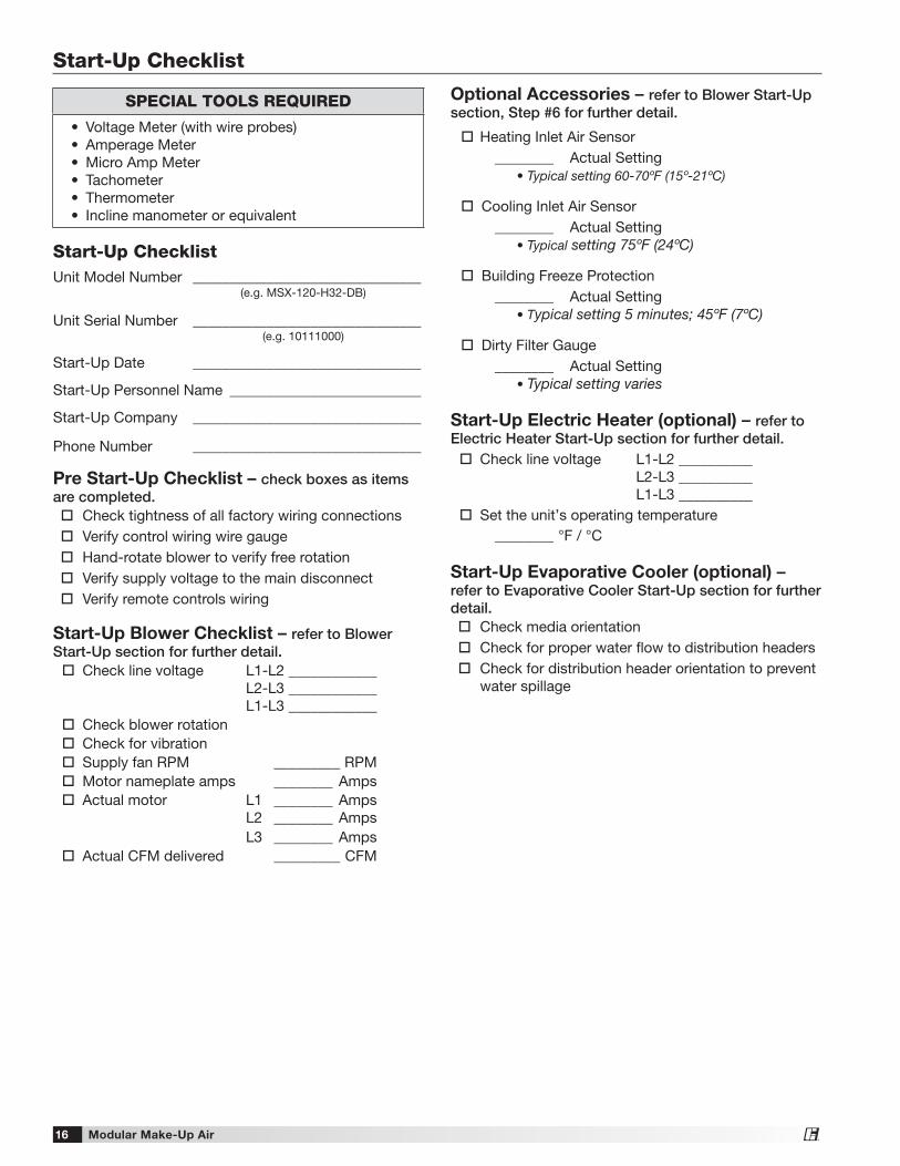
Start-Up ChecklistUnit Model Number _______________________________ (e.g. MSX-120-H32-DB)
Unit Serial Number _______________________________ (e.g. 10111000)
Start-Up Date _______________________________
Start-Up Personnel Name __________________________
Start-Up Company _______________________________
Phone Number _______________________________
Pre Start-Up Checklist – check boxes as items are completed. Check tightness of all factory wiring connections Verify control wiring wire gauge Hand-rotate blower to verify free rotation Verify supply voltage to the main disconnect Verify remote controls wiring
Start-Up Blower Checklist – refer to Blower Start-Up section for further detail. Check line voltage L1-L2 ____________ L2-L3 ____________ L1-L3 ____________ Check blower rotation Check for vibration Supply fan RPM _________ RPM Motor nameplate amps ________ Amps Actual motor L1 ________ Amps L2 ________ Amps L3 ________ Amps Actual CFM delivered _________ CFM
Optional Accessories – refer to Blower Start-Up section, Step #6 for further detail.
Heating Inlet Air Sensor ________ Actual Setting • Typical setting 60-70ºF (15º-21ºC)
Cooling Inlet Air Sensor ________ Actual Setting • Typical setting 75ºF (24ºC)
Building Freeze Protection ________ Actual Setting • Typical setting 5 minutes; 45ºF (7ºC)
Dirty Filter Gauge ________ Actual Setting • Typical setting varies
Start-Up Electric Heater (optional) – refer to Electric Heater Start-Up section for further detail. Check line voltage L1-L2 __________ L2-L3 __________ L1-L3 __________ Set the unit’s operating temperature ________ °F / °C
Start-Up Evaporative Cooler (optional) – refer to Evaporative Cooler Start-Up section for further detail. Check media orientation Check for proper water flow to distribution headers Check for distribution header orientation to prevent
water spillage
Start-Up Checklist
SPECIAL TOOLS REQUIRED
• Voltage Meter (with wire probes)• Amperage Meter• Micro Amp Meter• Tachometer• Thermometer• Incline manometer or equivalent
Modular Make-Up Air 17®
Pre Start-Up CheckRotate the fan wheel by hand and make sure no parts are rubbing. Check the V-belt drive for proper alignment and tension (a guide for proper belt tension and alignment is provided in the Belt Maintenance section). Check fasteners, set screws and locking collars on the fan, bearings, drive, motor base, and accessories for tightness.
1. Check the Voltage. Before starting the unit, compare the supplied voltage, hertz, and phase with the unit and motor’s nameplate information.
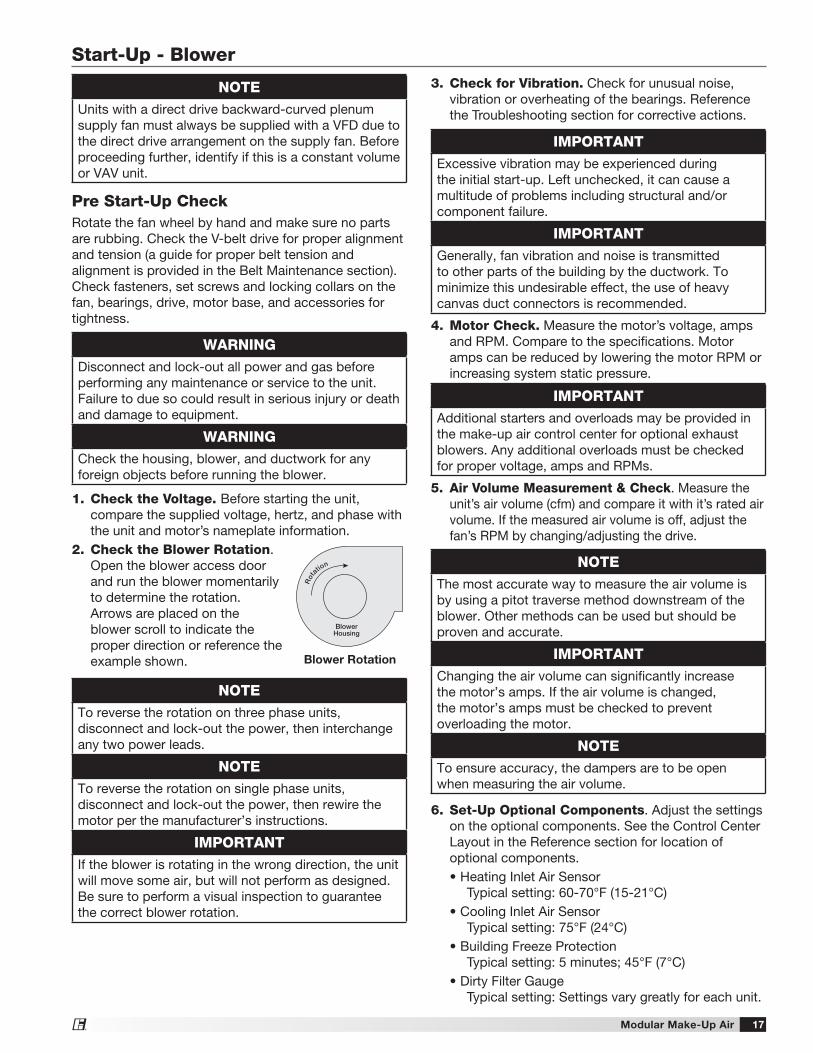
2. Check the Blower Rotation. Open the blower access door and run the blower momentarily to determine the rotation. Arrows are placed on the blower scroll to indicate the proper direction or reference the example shown.
NOTETo reverse the rotation on three phase units, disconnect and lock-out the power, then interchange any two power leads.
NOTETo reverse the rotation on single phase units, disconnect and lock-out the power, then rewire the motor per the manufacturer’s instructions.
IMPORTANTIf the blower is rotating in the wrong direction, the unit will move some air, but will not perform as designed. Be sure to perform a visual inspection to guarantee the correct blower rotation.
WARNINGDisconnect and lock-out all power and gas before performing any maintenance or service to the unit. Failure to due so could result in serious injury or death and damage to equipment.
WARNINGCheck the housing, blower, and ductwork for any foreign objects before running the blower.
3. Check for Vibration. Check for unusual noise, vibration or overheating of the bearings. Reference the Troubleshooting section for corrective actions.
4. Motor Check. Measure the motor’s voltage, amps and RPM. Compare to the specifications. Motor amps can be reduced by lowering the motor RPM or increasing system static pressure.
5. Air Volume Measurement & Check. Measure the unit’s air volume (cfm) and compare it with it’s rated air volume. If the measured air volume is off, adjust the fan’s RPM by changing/adjusting the drive.
6. Set-Up Optional Components. Adjust the settings on the optional components. See the Control Center Layout in the Reference section for location of optional components.
• Heating Inlet Air Sensor Typical setting: 60-70°F (15-21°C)
• Cooling Inlet Air Sensor Typical setting: 75°F (24°C)
• Building Freeze Protection Typical setting: 5 minutes; 45°F (7°C)
• Dirty Filter Gauge Typical setting: Settings vary greatly for each unit.
IMPORTANTExcessive vibration may be experienced during the initial start-up. Left unchecked, it can cause a multitude of problems including structural and/or component failure.
IMPORTANTGenerally, fan vibration and noise is transmitted to other parts of the building by the ductwork. To minimize this undesirable effect, the use of heavy canvas duct connectors is recommended.
IMPORTANTAdditional starters and overloads may be provided in the make-up air control center for optional exhaust blowers. Any additional overloads must be checked for proper voltage, amps and RPMs.
Blower Rotation
BlowerHousing
Rot
ation NOTE
The most accurate way to measure the air volume is by using a pitot traverse method downstream of the blower. Other methods can be used but should be proven and accurate.
IMPORTANTChanging the air volume can significantly increase the motor’s amps. If the air volume is changed, the motor’s amps must be checked to prevent overloading the motor.
NOTETo ensure accuracy, the dampers are to be open when measuring the air volume.
NOTEUnits with a direct drive backward-curved plenum supply fan must always be supplied with a VFD due to the direct drive arrangement on the supply fan. Before proceeding further, identify if this is a constant volume or VAV unit.
Start-Up - Blower
Modular Make-Up Air18®
Start-Up - Electric Heater (optional)
Pre Start-Up CheckCheck all electrical connections. Tighten any loose connection to all components including contactors, heating elements and main power lugs.
1. Check the Voltage. Before starting the heater, compare the supplied voltage, hertz, and phase with the heater’s nameplate information.
2. Airflow Interlock. With the supply fan on, verify the electric heater’s airflow interlock (DDS) is made.
3. Set the Unit’s Operating Temperature. Set the operating temperature by adjusting the discharge temperature selector. Typical settings are 65-70°F (18-21°C).
WARNINGDisconnect and lock-out all power before performing any maintenance or service to the unit. Failure to due so could result in serious injury or death and damage to equipment.
NOTEIf the heater is equipped with an optional inlet air sensor the heater will not energize unless the outdoor air temperature is less than the inlet air sensor’s set point.
Modular Make-Up Air 19®
The following economizer sequences will function to modulate the outdoor and return air dampers to determine and maximize the availability of free cooling. Although the Honeywell economizer controller contains numerous set points, the adjustment of only a few is necessary to ensure optimal performance.
SequencesEC-1 Outdoor Air Temperature ReferenceThis mode compares the outdoor air temperature to the dry bulb temperature set point (DRYBLB SET). Once the outdoor air temperature is less than DRYBLB SET, the unit will modulate the position of the dampers to maintain a predetermined mixed air temperature (MAT SET).
EC-2 Outdoor Air Enthalpy ReferenceThis mode compares the outdoor air enthalpy to a preset enthalpy curve. When the outdoor air conditions are within this curve, the dampers will modulate to maintain a mixed air temperature (MAT SET).
EC-3 Differential Temperature ReferenceThis mode compares the outdoor air temperature and the return air temperatures. If the outdoor air is cooler than the return, the dampers will modulate to maintain a preset mixed air temperature (MAT SET).
EC-4 Differential Enthalpy ReferenceThis mode compares the outdoor air enthalpy and the return air enthalpy. If the outdoor air enthalpy
Relevant Set Points1. MAT SET - The mixed air temperature set point.
The control will modulate the damper to maintain temperature as best as it can (Set point menu, Default 53°F)
2. LOW T LOCK - The set point for the low temperature mechanical cooling lockout. (Set point menu, Default 32°F)
3. DRYBLB SET - The outdoor air set point to call for economizer. (Set point menu, Default 63°F)
4. MIN POS - The minimum signal voltage sent to the dampers. This must be set to 2 VDC. (Set point menu, Default 2.8 VDC)
5. AUX1 O – The controllers operating sequence structure. (Set point menu, Default ‘None’)
6. ERV OAT SP - The set point for low temperature economizer lockout. This is the low temperature set point when AUX1 O is set to ERV. (Set point menu, Default 32°F)
7. STG3 DLY - Time delay after second cooling stage is enabled (Advanced setup menu, Default 2 hrs.)
Using the Keypad with Settings and ParametersTo use the keypad when working with Set points, System and Advanced Settings, Checkout tests, and Alarms: 1. Navigate to the desired menu.
2. Press (enter) to display the first item in the currently displayed menu.
3. Use the and buttons to scroll to the desired parameter.
4. Press (enter) to display the value of the currently displayed item.
5. Press the button to increase (change) the displayed parameter value.a
6. Press the button to increase (change) the displayed parameter value.a
7. Press (enter) to accept the displayed value and store it in non-volatile RAM.
8. CHANGE STORED displays.
9. Press (enter) to return the current menu parameter.
10. Press (escape) to return to the current menu parameter.
a When values are displayed, pressing and holding the or button causes the display to automatically
increment.
Modulate Dampers1. Navigate to the Checkout menu and press (Enter).2. The cooling should turn off.3. Navigate to Damper Open and press (enter) twice to
run the test.4. Voltage between terminals ACT 2-10 and ACT COM
should be 10 VDC. This will open the outdoor air damper and close the return air damper
5. Press (escape), navigate to Damper Close and press (enter) twice to run the test.
6. Voltage between terminal ACT 2-10 and ACT COM should be 2 VDC. This will close the outdoor air damper and open the return air damper.
Economizer (optional)
Modular Make-Up Air20®
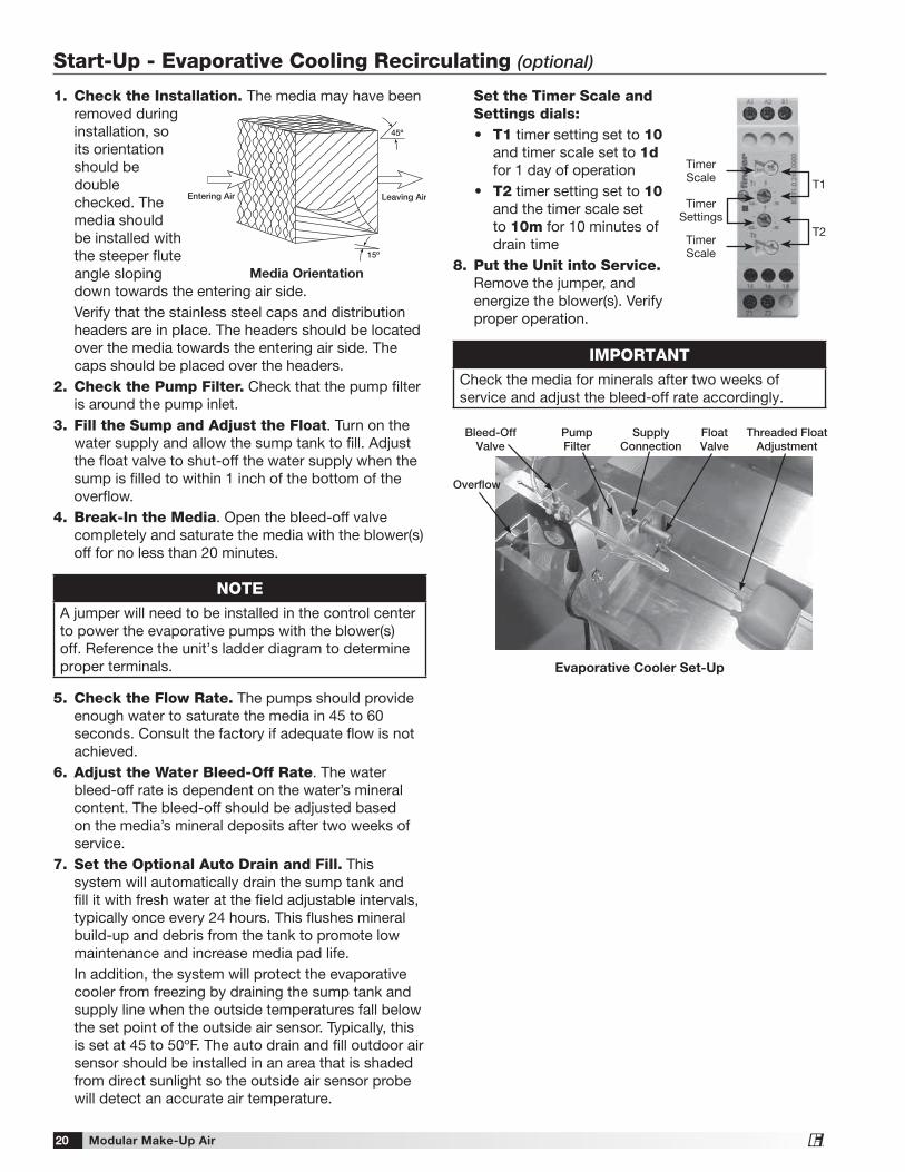
1. Check the Installation. The media may have been removed during installation, so its orientation should be double checked. The media should be installed with the steeper flute angle sloping down towards the entering air side.Verify that the stainless steel caps and distribution headers are in place. The headers should be located over the media towards the entering air side. The caps should be placed over the headers.
2. Check the Pump Filter. Check that the pump filter is around the pump inlet.
3. Fill the Sump and Adjust the Float. Turn on the water supply and allow the sump tank to fill. Adjust the float valve to shut-off the water supply when the sump is filled to within 1 inch of the bottom of the overflow.
4. Break-In the Media. Open the bleed-off valve completely and saturate the media with the blower(s) off for no less than 20 minutes.
5. Check the Flow Rate. The pumps should provide enough water to saturate the media in 45 to 60 seconds. Consult the factory if adequate flow is not achieved.
6. Adjust the Water Bleed-Off Rate. The water bleed-off rate is dependent on the water’s mineral content. The bleed-off should be adjusted based on the media’s mineral deposits after two weeks of service.
7. Set the Optional Auto Drain and Fill. This system will automatically drain the sump tank and fill it with fresh water at the field adjustable intervals, typically once every 24 hours. This flushes mineral build-up and debris from the tank to promote low maintenance and increase media pad life. In addition, the system will protect the evaporative cooler from freezing by draining the sump tank and supply line when the outside temperatures fall below the set point of the outside air sensor. Typically, this is set at 45 to 50ºF. The auto drain and fill outdoor air sensor should be installed in an area that is shaded from direct sunlight so the outside air sensor probe will detect an accurate air temperature.
IMPORTANTCheck the media for minerals after two weeks of service and adjust the bleed-off rate accordingly.
Leaving AirEntering Air
45º
15º
Media Orientation
Bleed-Off Valve
Overflow
Pump Filter
Threaded Float Adjustment
Supply Connection
Float Valve
Evaporative Cooler Set-Up
NOTEA jumper will need to be installed in the control center to power the evaporative pumps with the blower(s) off. Reference the unit’s ladder diagram to determine proper terminals.
Set the Timer Scale and Settings dials:• T1 timer setting set to 10
and timer scale set to 1d for 1 day of operation
• T2 timer setting set to 10 and the timer scale set to 10m for 10 minutes of drain time
8. Put the Unit into Service. Remove the jumper, and energize the blower(s). Verify proper operation.
T1
T2Timer Scale
Timer Scale
Timer Settings
Start-Up - Evaporative Cooling Recirculating (optional)
Modular Make-Up Air 21®
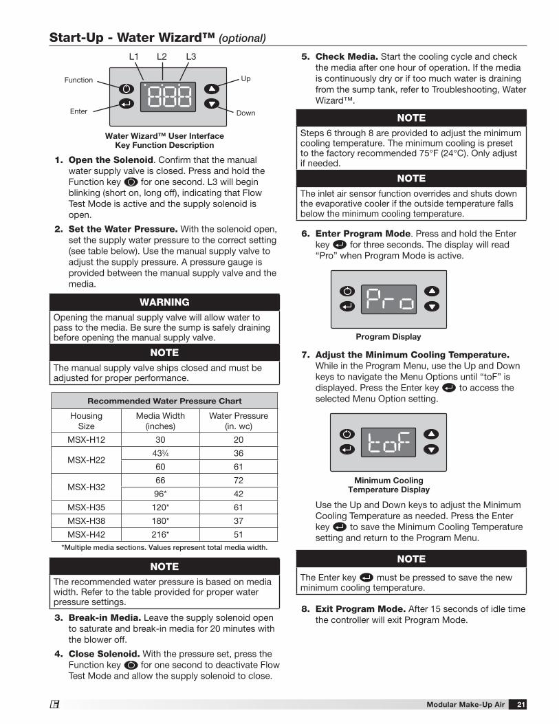
Recommended Water Pressure Chart
Housing Size
Media Width (inches)
Water Pressure (in. wc)
MSX-H12 30 20
MSX-H22433⁄4 36
60 61
MSX-H3266 72
96* 42
MSX-H35 120* 61
MSX-H38 180* 37
MSX-H42 216* 51*Multiple media sections. Values represent total media width.
WARNINGOpening the manual supply valve will allow water to pass to the media. Be sure the sump is safely draining before opening the manual supply valve.
NOTEThe manual supply valve ships closed and must be adjusted for proper performance.
NOTEThe recommended water pressure is based on media width. Refer to the table provided for proper water pressure settings.
Start-Up - Water Wizard™ (optional)
Program Display
NOTESteps 6 through 8 are provided to adjust the minimum cooling temperature. The minimum cooling is preset to the factory recommended 75°F (24°C). Only adjust if needed.
NOTEThe inlet air sensor function overrides and shuts down the evaporative cooler if the outside temperature falls below the minimum cooling temperature.
7. Adjust the Minimum Cooling Temperature. While in the Program Menu, use the Up and Down keys to navigate the Menu Options until “toF” is displayed. Press the Enter key to access the selected Menu Option setting.
Use the Up and Down keys to adjust the Minimum Cooling Temperature as needed. Press the Enter key to save the Minimum Cooling Temperature setting and return to the Program Menu.
Minimum Cooling Temperature Display
NOTE
The Enter key must be pressed to save the new minimum cooling temperature.
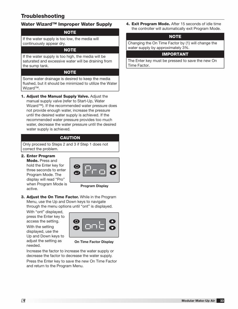
5. Check Media. Start the cooling cycle and check the media after one hour of operation. If the media is continuously dry or if too much water is draining from the sump tank, refer to Troubleshooting, Water Wizard™.
6. Enter Program Mode. Press and hold the Enter key for three seconds. The display will read “Pro” when Program Mode is active.
Water Wizard™ User Interface Key Function Description
Function
L1 L2 L3
Enter
Up
Down
1. Open the Solenoid. Confirm that the manual water supply valve is closed. Press and hold the Function key for one second. L3 will begin blinking (short on, long off), indicating that Flow Test Mode is active and the supply solenoid is open.
2. Set the Water Pressure. With the solenoid open, set the supply water pressure to the correct setting (see table below). Use the manual supply valve to adjust the supply pressure. A pressure gauge is provided between the manual supply valve and the media.
3. Break-in Media. Leave the supply solenoid open to saturate and break-in media for 20 minutes with the blower off.
4. Close Solenoid. With the pressure set, press the Function key for one second to deactivate Flow Test Mode and allow the supply solenoid to close.
8. Exit Program Mode. After 15 seconds of idle time the controller will exit Program Mode.
Modular Make-Up Air22®
Microprocessor (optional)
If the optional microprocessor is mounted in the control center of the unit, it may be configured to control the VFD.
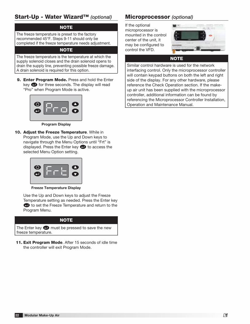
9. Enter Program Mode. Press and hold the Enter key for three seconds. The display will read “Pro” when Program Mode is active.
10. Adjust the Freeze Temperature. While in Program Mode, use the Up and Down keys to navigate through the Menu Options until “Frt” is displayed. Press the Enter key to access the selected Menu Option setting.
Use the Up and Down keys to adjust the Freeze Temperature setting as needed. Press the Enter key
to set the Freeze Temperature and return to the Program Menu.
11. Exit Program Mode. After 15 seconds of idle time the controller will exit Program Mode.
NOTEThe freeze temperature is preset to the factory recommended 45°F. Steps 9-11 should only be completed if the freeze temperature needs adjustment.
NOTEThe freeze temperature is the temperature at which the supply solenoid closes and the drain solenoid opens to drain the supply line, preventing possible freeze damage. A drain solenoid is required for this option.
Program Display
Freeze Temperature Display
NOTE
The Enter key must be pressed to save the new freeze temperature.
Start-Up - Water Wizard™ (optional)
NOTESimilar control hardware is used for the network interfacing control. Only the microprocessor controller will contain keypad buttons on both the left and right side of the display. For any other hardware, please reference the Check Operation section. If the make-up air unit has been supplied with the microprocessor controller, additional information can be found by referencing the Microprocessor Controller Installation, Operation and Maintenance Manual.
Modular Make-Up Air 23®
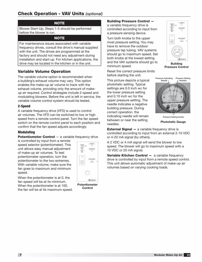
Building Pressure Control — a variable frequency drive is controlled according to input from a pressure sensing device.
Turn both knobs to the upper most pressure setting. You may have to remove the outdoor pressure tap tubing. VAV systems should go to maximum speed. Set both knobs at the lowest setting and the VAV systems should go to minimum speed.
Reset the correct pressure limits before starting the unit.
This picture depicts a typical photohelic setting. Typical settings are 0.0 inch wc for the lower pressure setting and 0.10 inch wc for the upper pressure setting. The needle indicates a negative building pressure. During correct operation, the indicating needle will remain between or near the setting needles.
External Signal — a variable frequency drive is controlled according to input from an external 2-10 VDC or 4-20 mA signal (by others).
A 2 VDC or 4 mA signal will send the blower to low speed. The blower will go to maximum speed with a 10 VDC or 20 mA signal.
Variable Kitchen Control — a variable frequency drive is controlled by input from a remote speed control. This unit allows automatic adjustment of make-up air volumes based on varying cooking loads.
7065
75
80
85
90
60
55
(OPTIONAL)
BLOWER
DIRTY FILTERS
MAIN VALVES
EXHAUST
SUPPLY
HEAT
(OPTIONAL)
GREENHECK®
PHOTOHELIC
BuildingPressure Control
Pressure Setting Knobs
Pressure Setting Needles
Pressure Indicating Needle
Photohelic Gauge
NOTEBlower Start-Up, Steps 1-5 should be performed before the blower is run.
NOTEFor maintenance issues associated with variable frequency drives, consult the drive’s manual supplied with the unit. The drives are programmed at the factory and should not need any adjustment during installation and start-up. For kitchen applications, the drive may be located in the kitchen or in the unit.
Variable Volume OperationThe variable volume option is recommended when a building’s exhaust volume may vary. This option enables the make-up air volume to track with the exhaust volume, providing only the amount of make-up air required. Control strategies include 2-speed and modulating blowers. Before the unit is left in service, the variable volume control system should be tested.
2-SpeedA variable frequency drive (VFD) is used to control air volumes. The VFD can be switched to low or high speed from a remote control panel. Turn the fan speed switch on the remote control panel to each position and confirm that the fan speed adjusts accordingly.
ModulatingPotentiometer Control — a variable frequency drive is controlled by input from a remote speed selector (potentiometer). This unit allows easy manual adjustment of make-up air volumes. To test potentiometer operation, turn the potentiometer to the two extremes. With variable volume, make sure the fan goes to maximum and minimum speed.
When the potentiometer is at 0, the fan speed will be at its minimum. When the potentiometer is at 100, the fan will be at its maximum speed.
7065
75
80
85
90
60
55
(OPTIONAL)
BLOWER
DIRTY FILTERS
MAIN VALVES
EXHAUST
SUPPLY
HEAT
(OPTIONAL)
GREENHECK®
PotentiometerControl
Check Operation - VAV Units (optional)
Modular Make-Up Air24®
Check Operation - Recirculating Units (optional)
NOTEBlower Start-Up, steps 1-5 should be performed before the blower is run.
Recirculation OperationThe recirculation operation option is recommended when the ventilation equipment provides the primary source of heating for the space. Recirculation can vary from 100% return air to 100% outside air. Control strategies include 2-position and modulating dampers.
Before the unit is left in service, the recirculation control system should be tested.
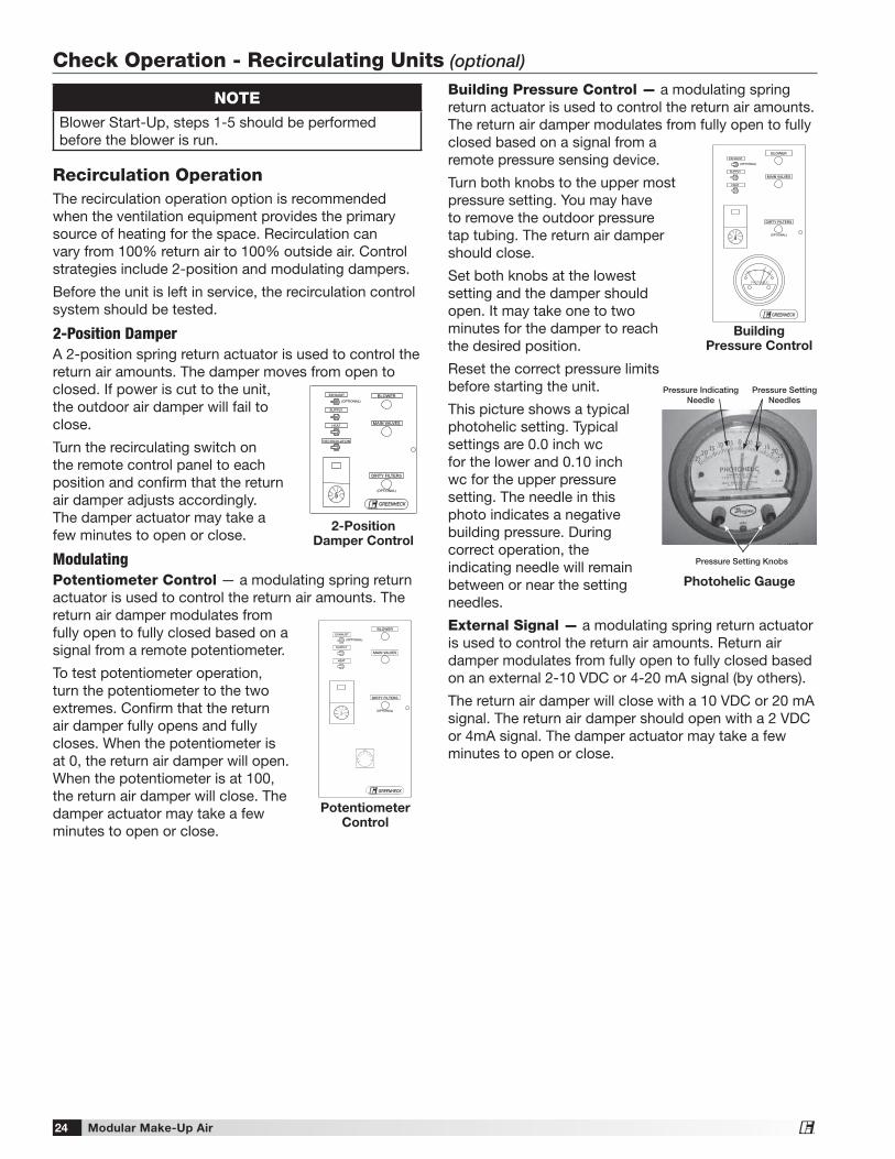
2-Position DamperA 2-position spring return actuator is used to control the return air amounts. The damper moves from open to closed. If power is cut to the unit, the outdoor air damper will fail to close.
Turn the recirculating switch on the remote control panel to each position and confirm that the return air damper adjusts accordingly. The damper actuator may take a few minutes to open or close.
ModulatingPotentiometer Control — a modulating spring return actuator is used to control the return air amounts. The return air damper modulates from fully open to fully closed based on a signal from a remote potentiometer.
To test potentiometer operation, turn the potentiometer to the two extremes. Confirm that the return air damper fully opens and fully closes. When the potentiometer is at 0, the return air damper will open. When the potentiometer is at 100, the return air damper will close. The damper actuator may take a few minutes to open or close.
70 65
75
80
85
90
60
55
GREENHECK ®
(OPTIONAL)
BLOWER
DIRTY FIL TERS
MAIN V AL VES
RECIRCULA TION
EXHAUST
SUPPL Y
HEA T
(OPTIONAL)
2-Position Damper Control
7065
75
80
85
90
60
55
(OPTIONAL)
BLOWER
DIRTY FILTERS
MAIN VALVES
EXHAUST
SUPPLY
HEAT
(OPTIONAL)
GREENHECK®
PotentiometerControl
Building Pressure Control — a modulating spring return actuator is used to control the return air amounts. The return air damper modulates from fully open to fully closed based on a signal from a remote pressure sensing device.
Turn both knobs to the upper most pressure setting. You may have to remove the outdoor pressure tap tubing. The return air damper should close.
Set both knobs at the lowest setting and the damper should open. It may take one to two minutes for the damper to reach the desired position.
Reset the correct pressure limits before starting the unit.
This picture shows a typical photohelic setting. Typical settings are 0.0 inch wc for the lower and 0.10 inch wc for the upper pressure setting. The needle in this photo indicates a negative building pressure. During correct operation, the indicating needle will remain between or near the setting needles.
External Signal — a modulating spring return actuator is used to control the return air amounts. Return air damper modulates from fully open to fully closed based on an external 2-10 VDC or 4-20 mA signal (by others).
The return air damper will close with a 10 VDC or 20 mA signal. The return air damper should open with a 2 VDC or 4mA signal. The damper actuator may take a few minutes to open or close.
Pressure Setting Knobs
Pressure Setting Needles
Pressure Indicating Needle
Photohelic Gauge
7065
75
80
85
90
60
55
(OPTIONAL)
BLOWER
DIRTY FILTERS
MAIN VALVES
EXHAUST
SUPPLY
HEAT
(OPTIONAL)
GREENHECK®
PHOTOHELIC
BuildingPressure Control
Modular Make-Up Air 25®
Electrical Sequence1. Exhaust Fan Contact (S1) Closed (optional) • Power passes through N.C. contact on exhaust
fan overload (ST2 OL), which is closed if exhaust fan (M2) has not overloaded
• Power passes to exhaust fan starter (ST2) • N.O. contact on exhaust fan starter (ST2) is
energized and closed • Power passes to exhaust fan • Exhaust fan (M2) starts2. Supply Fan Contact (S2) Closed • Power passes through N.C. field-supplied fire
contact (FSC) • Power passes through optional N.O. contact on
exhaust fan starter (ST2), which is closed when the optional exhaust starter (ST2) is activated
• Power passes through N.C. contact on supply starter overload (ST1 OL), which is closed if the supply fan has not overloaded
• Power passes through N.C. contact on optional freeze protection timer (RT4) which remains closed if the temperature has remained above the set point
• Power passes to and energizes optional inlet damper (D1), which opens
• Power passes through optional N.O. damper limit switch (DL1), which is energized and closed when the optional inlet damper is open. It may take several minutes for the damper to fully open and for the damper limit switch to close
• Power passes to and energizes fan relay (RF) • Power passes through N.O. contact on fan relay
(RF), which closes when the fan relay (RF) is energized
• Power passes to and energizes supply fan starter (ST1)
• N.O. contact on supply fan starter (ST1) is energized and closed
• Supply fan (M1) starts
3. Electric Heat Contact (S4) Closed (optional) • Power passes through N.O. contact on fan relay
(RF), which is energized and closed • Power passes through N.C. contact on optional
inlet air sensor (TS4), which is closed if the inlet air temperature is below the set point
• Power passes to and energizes heat relay (RH) • Power passes through N.O. contact on heat relay
(RH), which closes when the heat relay (RH) is energized
• Power passes through N.O. contact on pressure differential switch (PDS), which closes when proper airflow is achieved
• Power passes through N.C. automatic and manual reset temperature cutouts (A and M), which remain closed if the maximum temperature has not been reached
• Power passes to and energizes operating contactor relay (C1)
• Power passes through N.O. contacts on operating contactor (C1), which is closed
• Electric heater modulates/stages to maintain temperature set point
4. Evaporative Cooling Contact (S4) Closed* (optional)• N.O. contact on fan relay (RF) is energized and
closed• Power passes through N.O. contact on optional
inlet air sensor (TS4), which is energized and closed if the inlet air temperature is above the set point
• Power passes to and energizes cool relay (RC)• N.O. contact on cool relay (RC) is energized and
closed• Power passes to optional evaporative cooling
pump (P1)*If DX or chilled water coils are used rather than an evaporative cooler, the cooling sequence of operation will depend on the coil controls. Cooling coil controls are supplied by others.
Operation - Electrical
Modular Make-Up Air26®
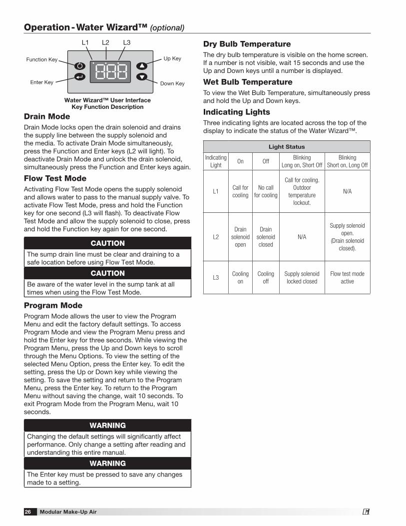
Drain ModeDrain Mode locks open the drain solenoid and drains the supply line between the supply solenoid and the media. To activate Drain Mode simultaneously, press the Function and Enter keys (L2 will light). To deactivate Drain Mode and unlock the drain solenoid, simultaneously press the Function and Enter keys again.
Flow Test ModeActivating Flow Test Mode opens the supply solenoid and allows water to pass to the manual supply valve. To activate Flow Test Mode, press and hold the Function key for one second (L3 will flash). To deactivate Flow Test Mode and allow the supply solenoid to close, press and hold the Function key again for one second.
Program ModeProgram Mode allows the user to view the Program Menu and edit the factory default settings. To access Program Mode and view the Program Menu press and hold the Enter key for three seconds. While viewing the Program Menu, press the Up and Down keys to scroll through the Menu Options. To view the setting of the selected Menu Option, press the Enter key. To edit the setting, press the Up or Down key while viewing the setting. To save the setting and return to the Program Menu, press the Enter key. To return to the Program Menu without saving the change, wait 10 seconds. To exit Program Mode from the Program Menu, wait 10 seconds.
Operation - Water Wizard™ (optional)
CAUTIONThe sump drain line must be clear and draining to a safe location before using Flow Test Mode.
CAUTIONBe aware of the water level in the sump tank at all times when using the Flow Test Mode.
WARNINGChanging the default settings will significantly affect performance. Only change a setting after reading and understanding this entire manual.
WARNINGThe Enter key must be pressed to save any changes made to a setting.
Dry Bulb TemperatureThe dry bulb temperature is visible on the home screen. If a number is not visible, wait 15 seconds and use the Up and Down keys until a number is displayed.
Wet Bulb TemperatureTo view the Wet Bulb Temperature, simultaneously press and hold the Up and Down keys.
Indicating LightsThree indicating lights are located across the top of the display to indicate the status of the Water Wizard™.
Light Status
Indicating
LightOn Off
Blinking
Long on, Short Off
Blinking
Short on, Long Off
L1Call for
cooling
No call
for cooling
Call for cooling.
Outdoor
temperature
lockout.
N/A
L2
Drain
solenoid
open
Drain
solenoid
closed
N/A
Supply solenoid
open.
(Drain solenoid
closed).
L3Cooling
on
Cooling
off
Supply solenoid
locked closed
Flow test mode
active
Water Wizard™ User Interface Key Function Description
Function Key
L1 L2 L3
Enter Key
Up Key
Down Key
Modular Make-Up Air 27®
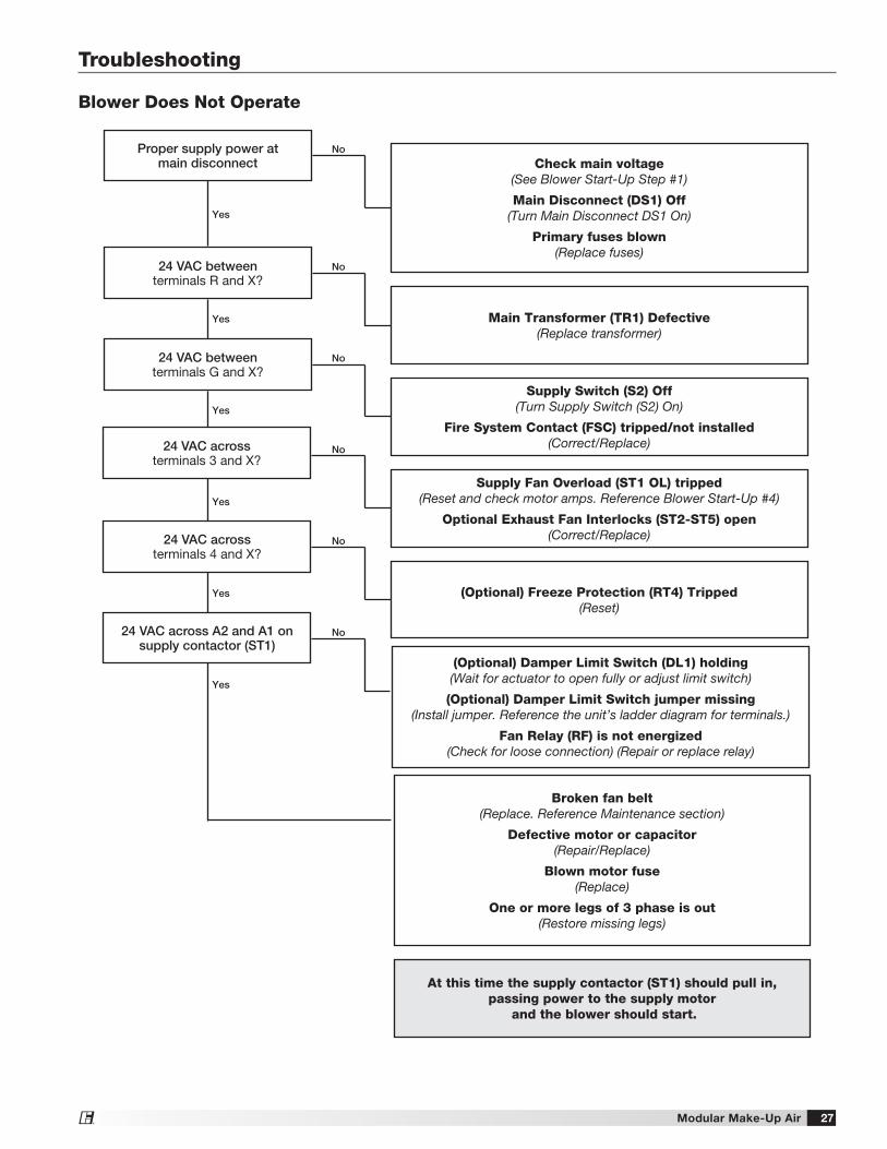
Proper supply power at main disconnect
24 VAC betweenterminals R and X?
24 VAC betweenterminals G and X?
No
No
No
No
No
No
Yes
Yes
Yes
Yes
Yes
Yes
Blower Does Not Operate
24 VAC across A2 and A1 on supply contactor (ST1)
24 VAC acrossterminals 4 and X?
24 VAC acrossterminals 3 and X?
Troubleshooting
Check main voltage(See Blower Start-Up Step #1)
Main Disconnect (DS1) Off(Turn Main Disconnect DS1 On)
Primary fuses blown(Replace fuses)
Main Transformer (TR1) Defective(Replace transformer)
Supply Switch (S2) Off(Turn Supply Switch (S2) On)
Fire System Contact (FSC) tripped/not installed(Correct/Replace)
Broken fan belt(Replace. Reference Maintenance section)
Defective motor or capacitor(Repair/Replace)
Blown motor fuse(Replace)
One or more legs of 3 phase is out(Restore missing legs)
Supply Fan Overload (ST1 OL) tripped(Reset and check motor amps. Reference Blower Start-Up #4)
Optional Exhaust Fan Interlocks (ST2-ST5) open(Correct/Replace)
(Optional) Damper Limit Switch (DL1) holding(Wait for actuator to open fully or adjust limit switch)
(Optional) Damper Limit Switch jumper missing(Install jumper. Reference the unit’s ladder diagram for terminals.)
Fan Relay (RF) is not energized(Check for loose connection) (Repair or replace relay)
(Optional) Freeze Protection (RT4) Tripped(Reset)
At this time the supply contactor (ST1) should pull in, passing power to the supply motor
and the blower should start.
Modular Make-Up Air28®
Troubleshooting
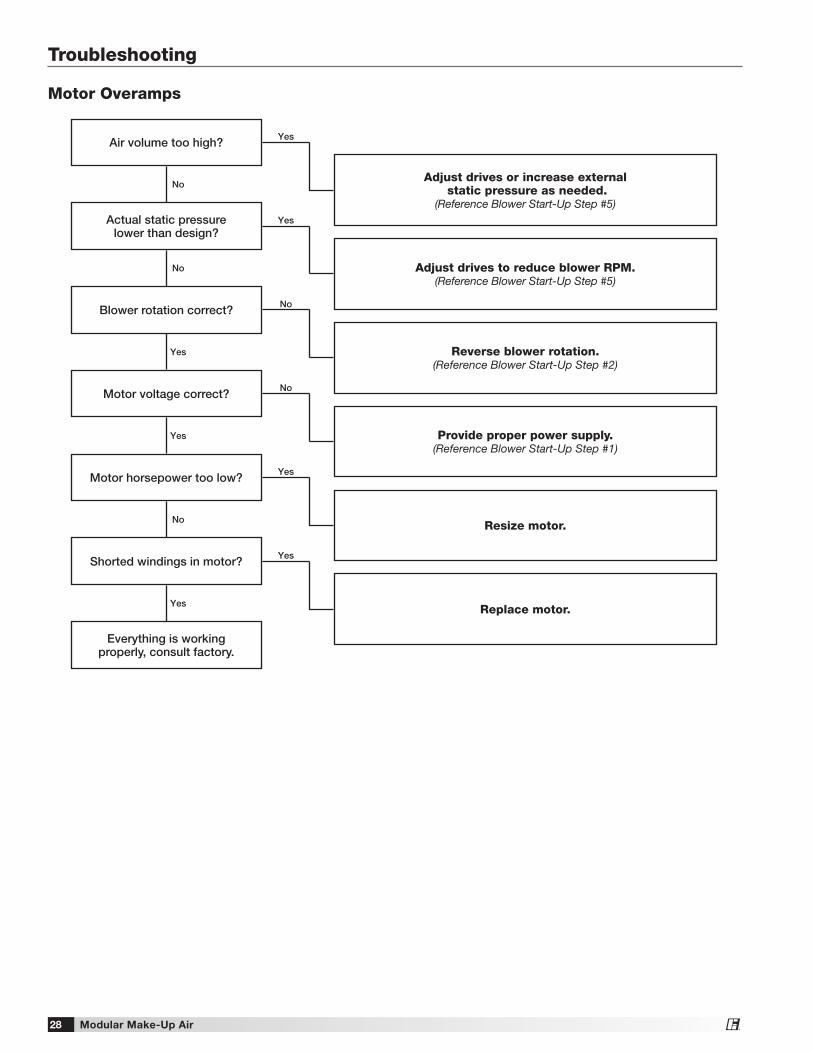
Motor Overamps
Air volume too high?
Motor horsepower too low?
Motor voltage correct?
Blower rotation correct?
Actual static pressure lower than design?
No
No
Yes
Yes
Yes
Yes
No
Yes
No
No
Shorted windings in motor? Yes
Everything is working properly, consult factory.
Yes
Adjust drives or increase external static pressure as needed.
(Reference Blower Start-Up Step #5)
Resize motor.
Provide proper power supply.(Reference Blower Start-Up Step #1)
Reverse blower rotation.(Reference Blower Start-Up Step #2)
Adjust drives to reduce blower RPM.(Reference Blower Start-Up Step #5)
Replace motor.
Modular Make-Up Air 29®
Troubleshooting
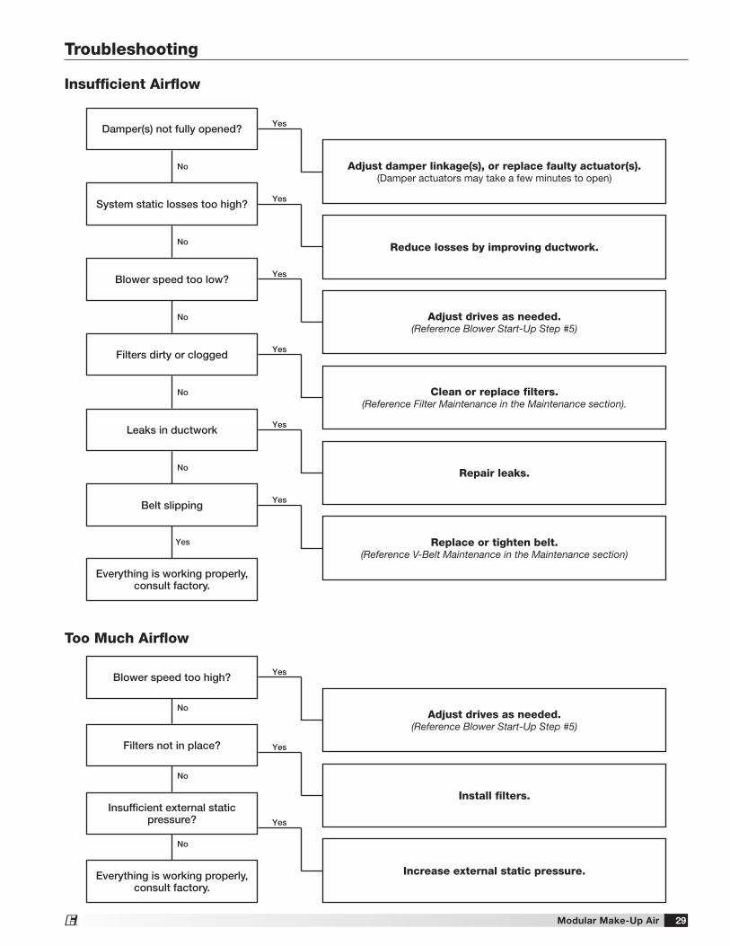
Too Much Airflow
Blower speed too high?
Adjust drives as needed.(Reference Blower Start-Up Step #5)
Insufficient external static pressure?
Increase external static pressure.
Filters not in place?
Install filters.
Yes
Yes
Yes
No
No
Everything is working properly, consult factory.
No
Insufficient Airflow
Damper(s) not fully opened?
Filters dirty or clogged
Blower speed too low?
System static losses too high?
Yes
Yes
Yes
Yes
No
No
No
No
No
Leaks in ductwork Yes
Belt slipping Yes
Everything is working properly, consult factory.
Yes
Adjust damper linkage(s), or replace faulty actuator(s).(Damper actuators may take a few minutes to open)
Clean or replace filters.(Reference Filter Maintenance in the Maintenance section).
Adjust drives as needed.(Reference Blower Start-Up Step #5)
Reduce losses by improving ductwork.
Repair leaks.
Replace or tighten belt.(Reference V-Belt Maintenance in the Maintenance section)
Modular Make-Up Air30®
Troubleshooting
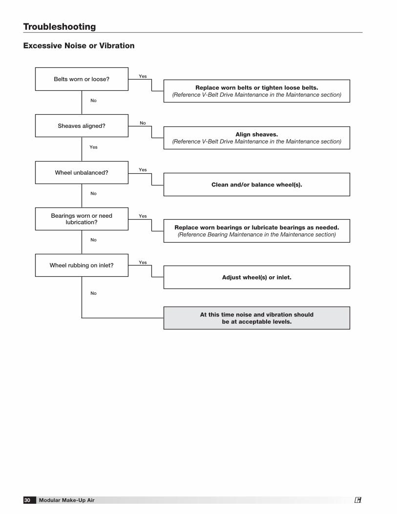
Excessive Noise or Vibration
Sheaves aligned?
Wheel unbalanced?
Belts worn or loose?
Yes
Yes
No
No
Yes
Bearings worn or need lubrication?
Yes
No
Wheel rubbing on inlet? Yes
No
No
Align sheaves.(Reference V-Belt Drive Maintenance in the Maintenance section)
Clean and/or balance wheel(s).
Replace worn belts or tighten loose belts.(Reference V-Belt Drive Maintenance in the Maintenance section)
Replace worn bearings or lubricate bearings as needed.(Reference Bearing Maintenance in the Maintenance section)
Adjust wheel(s) or inlet.
At this time noise and vibration should be at acceptable levels.
Modular Make-Up Air 31®
Troubleshooting
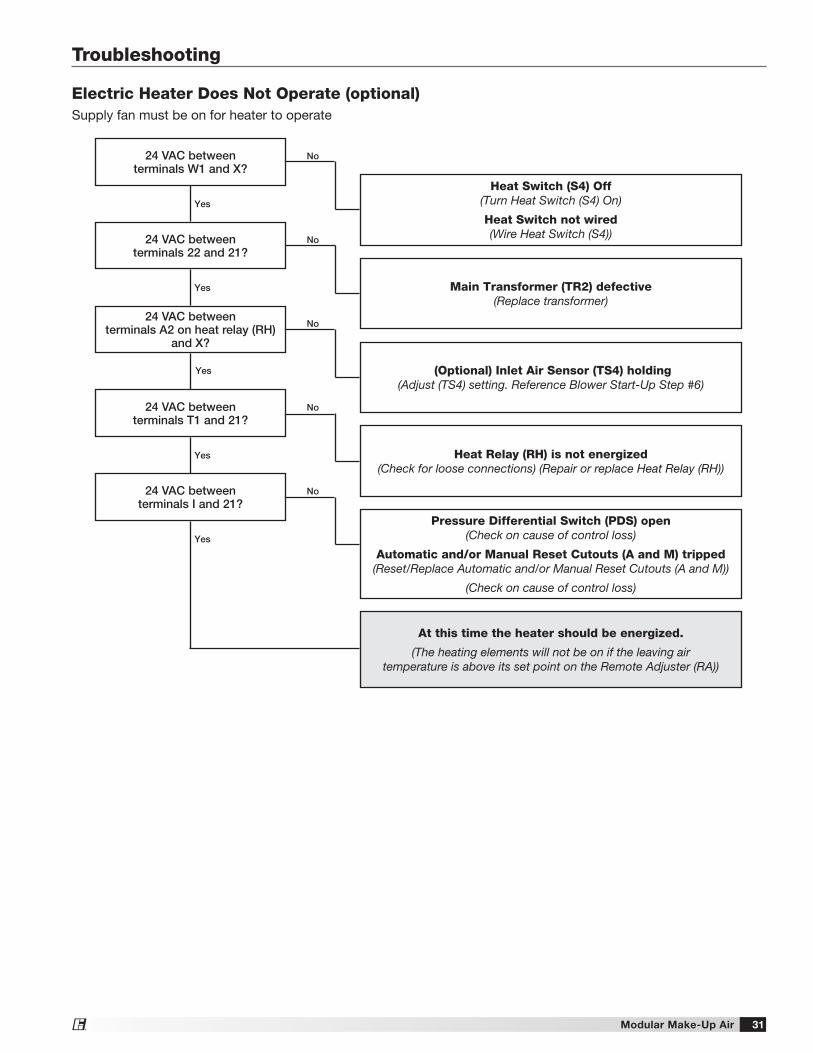
Electric Heater Does Not Operate (optional)Supply fan must be on for heater to operate
24 VAC between terminals W1 and X?
24 VAC between terminals 22 and 21?
24 VAC between terminals I and 21?
24 VAC between terminals T1 and 21?
24 VAC between terminals A2 on heat relay (RH)
and X?
No
No
No
No
No
Yes
Yes
Yes
Yes
Yes
Heat Switch (S4) Off (Turn Heat Switch (S4) On)
Heat Switch not wired(Wire Heat Switch (S4))
Main Transformer (TR2) defective(Replace transformer)
Heat Relay (RH) is not energized(Check for loose connections) (Repair or replace Heat Relay (RH))
(Optional) Inlet Air Sensor (TS4) holding(Adjust (TS4) setting. Reference Blower Start-Up Step #6)
At this time the heater should be energized.
(The heating elements will not be on if the leaving air temperature is above its set point on the Remote Adjuster (RA))
Pressure Differential Switch (PDS) open (Check on cause of control loss)
Automatic and/or Manual Reset Cutouts (A and M) tripped (Reset/Replace Automatic and/or Manual Reset Cutouts (A and M))
(Check on cause of control loss)
Modular Make-Up Air32®
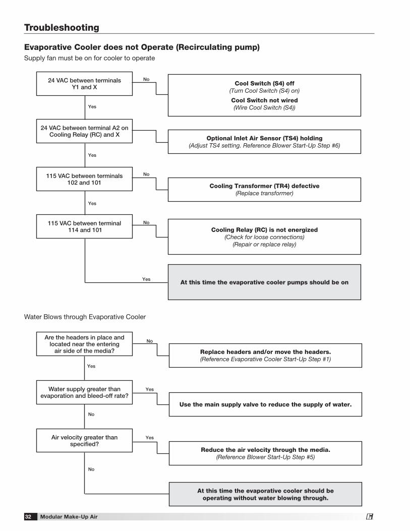
Evaporative Cooler does not Operate (Recirculating pump)Supply fan must be on for cooler to operate
Troubleshooting
Water Blows through Evaporative Cooler
Water supply greater than evaporation and bleed-off rate?
Use the main supply valve to reduce the supply of water.
Air velocity greater than specified?
Reduce the air velocity through the media.(Reference Blower Start-Up Step #5)
At this time the evaporative cooler should be operating without water blowing through.
Are the headers in place and located near the entering
air side of the media? Replace headers and/or move the headers.(Reference Evaporative Cooler Start-Up Step #1)
Yes
No
Yes
Yes
No
No
115 VAC between terminals102 and 101
24 VAC between terminal A2 on Cooling Relay (RC) and X
Cooling Transformer (TR4) defective (Replace transformer)
Optional Inlet Air Sensor (TS4) holding(Adjust TS4 setting. Reference Blower Start-Up Step #6)
115 VAC between terminal 114 and 101 Cooling Relay (RC) is not energized
(Check for loose connections)(Repair or replace relay)
24 VAC between terminalsY1 and X
Cool Switch (S4) off(Turn Cool Switch (S4) on)
Cool Switch not wired(Wire Cool Switch (S4))
No
No
No
Yes
Yes
Yes
At this time the evaporative cooler pumps should be onYes
Modular Make-Up Air 33®
NOTEIf the water supply is too low, the media will continuously appear dry.
NOTEIf the water supply is too high, the media will be saturated and excessive water will be draining from the sump tank.
NOTESome water drainage is desired to keep the media flushed, but it should be minimized to utilize the Water Wizard™.
CAUTIONOnly proceed to Steps 2 and 3 if Step 1 does not correct the problem.
NOTEChanging the On Time Factor by (1) will change the water supply by approximately 3%.
IMPORTANTThe Enter key must be pressed to save the new On Time Factor.
1. Adjust the Manual Supply Valve. Adjust the manual supply valve (refer to Start-Up, Water Wizard™). If the recommended water pressure does not provide enough water, increase the pressure until the desired water supply is achieved. If the recommended water pressure provides too much water, decrease the water pressure until the desired water supply is achieved.
TroubleshootingWater Wizard™ Improper Water Supply
2. Enter Program Mode. Press and hold the Enter key for three seconds to enter Program Mode. The display will read “Pro” when Program Mode is active.
3. Adjust the On Time Factor. While in the Program Menu, use the Up and Down keys to navigate through the menu options until “ont” is displayed.
With “ont” displayed, press the Enter key to access the setting.
With the setting displayed, use the Up and Down keys to adjust the setting as needed.
Increase the factor to increase the water supply or decrease the factor to decrease the water supply.
Press the Enter key to save the new On Time Factor and return to the Program Menu.
4. Exit Program Mode. After 15 seconds of idle time the controller will automatically exit Program Mode.
Program Display
On Time Factor Display
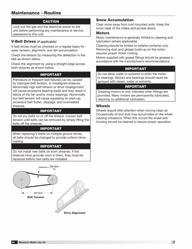
Modular Make-Up Air34®
Maintenance - Routine
CAUTIONLock-out the gas and the electrical power to the unit before performing any maintenance or service operations to this unit.
V-Belt Drives (if applicable) V-belt drives must be checked on a regular basis for wear, tension, alignment, and dirt accumulation.
Check the tension by measuring the deflection in the belt as shown below.
Check the alignment by using a straight edge across both sheaves as shown below.
Snow AccumulationClear snow away from roof mounted units. Keep the snow clear of the intake and access doors.
MotorsMotor maintenance is generally limited to cleaning and lubrication (where applicable).Cleaning should be limited to exterior surfaces only. Removing dust and grease build-up on the motor assures proper motor cooling.Motors supplied with grease fittings should be greased in accordance with the manufacturer’s recommendations.
WheelsWheels require little attention when moving clean air. Occasionally oil and dust may accumulate on the wheel causing imbalance. When this occurs the wheel and housing should be cleaned to assure proper operation.
Belt Tension
Belt Span
Deflection = Belt Span64
Drive Alignment
IMPORTANTPremature or frequent belt failures can be caused by improper belt tension, or misaligned sheaves. Abnormally high belt tension or drive misalignment will cause excessive bearing loads and may result in failure of the fan and/or motor bearings. Abnormally low belt tension will cause squealing on start-up, excessive belt flutter, slippage, and overheated sheaves.
IMPORTANTDo not pry belts on or off the sheave. Loosen belt tension until belts can be removed by simply lifting the belts off the sheaves.
IMPORTANTWhen replacing V-belts on multiple groove drives, all belts should be changed to provide uniform drive loading.
IMPORTANTDo not install new belts on worn sheaves. If the sheaves have grooves worn in them, they must be replaced before new belts are installed.
IMPORTANTDo not allow water or solvents to enter the motor or bearings. Motors and bearings should never be sprayed with steam, water or solvents.
IMPORTANTGreasing motors is only intended when fittings are provided. Many motors are permanently lubricated, requiring no additional lubrication.
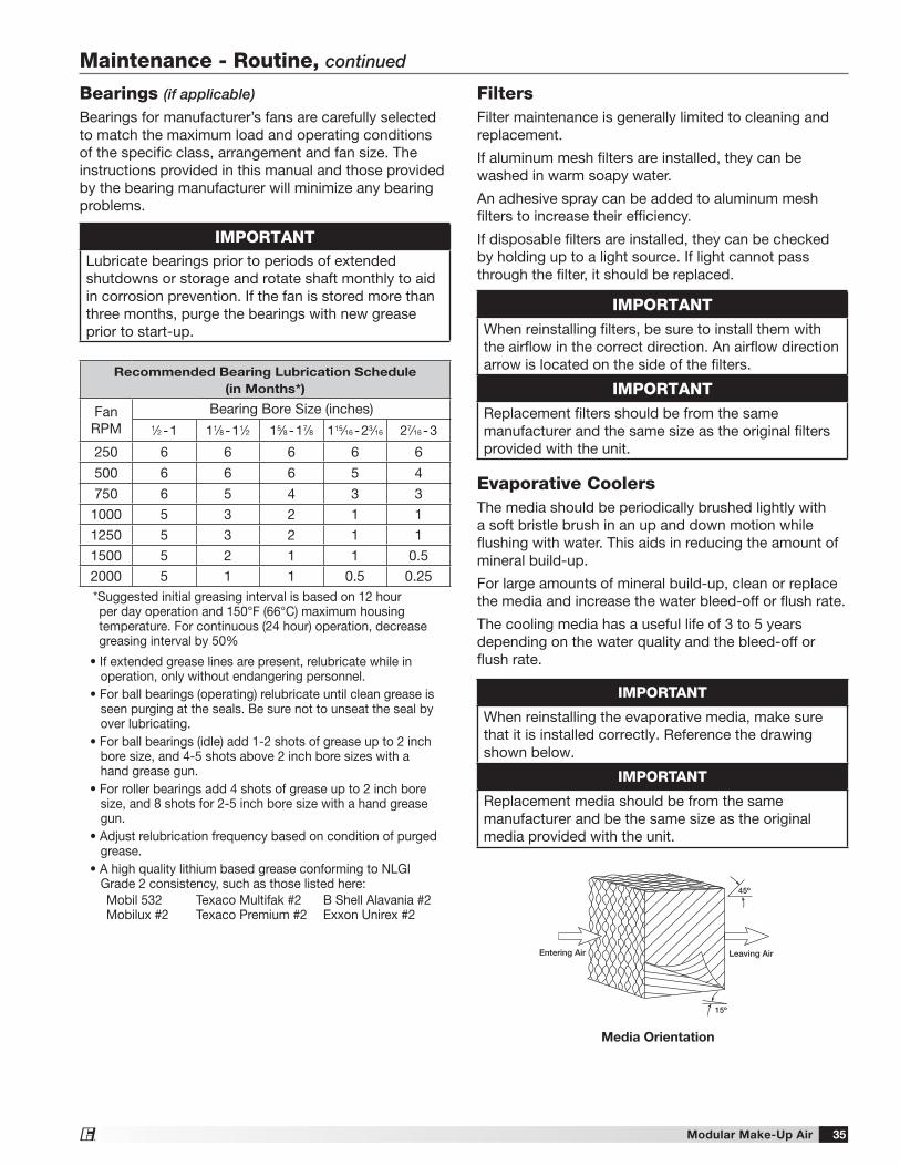
Modular Make-Up Air 35®
Maintenance - Routine, continued
FiltersFilter maintenance is generally limited to cleaning and replacement.
If aluminum mesh filters are installed, they can be washed in warm soapy water.
An adhesive spray can be added to aluminum mesh filters to increase their efficiency.
If disposable filters are installed, they can be checked by holding up to a light source. If light cannot pass through the filter, it should be replaced.
IMPORTANTWhen reinstalling filters, be sure to install them with the airflow in the correct direction. An airflow direction arrow is located on the side of the filters.
IMPORTANTReplacement filters should be from the same manufacturer and the same size as the original filters provided with the unit.
Evaporative CoolersThe media should be periodically brushed lightly with a soft bristle brush in an up and down motion while flushing with water. This aids in reducing the amount of mineral build-up.
For large amounts of mineral build-up, clean or replace the media and increase the water bleed-off or flush rate.
The cooling media has a useful life of 3 to 5 years depending on the water quality and the bleed-off or flush rate.
Leaving AirEntering Air
45º
15º
Media Orientation
IMPORTANT
When reinstalling the evaporative media, make sure that it is installed correctly. Reference the drawing shown below.
IMPORTANT
Replacement media should be from the same manufacturer and be the same size as the original media provided with the unit.
Bearings (if applicable)
Bearings for manufacturer’s fans are carefully selected to match the maximum load and operating conditions of the specific class, arrangement and fan size. The instructions provided in this manual and those provided by the bearing manufacturer will minimize any bearing problems.
IMPORTANTLubricate bearings prior to periods of extended shutdowns or storage and rotate shaft monthly to aid in corrosion prevention. If the fan is stored more than three months, purge the bearings with new grease prior to start-up.
Recommended Bearing Lubrication Schedule
(in Months*)
FanRPM
Bearing Bore Size (inches)1⁄2 - 1 11⁄8 - 11⁄2 15⁄8 - 17⁄8 115⁄16 - 23⁄16 27⁄16 - 3
250 6 6 6 6 6
500 6 6 6 5 4
750 6 5 4 3 3
1000 5 3 2 1 1
1250 5 3 2 1 1
1500 5 2 1 1 0.5
2000 5 1 1 0.5 0.25*Suggested initial greasing interval is based on 12 hour per day operation and 150°F (66°C) maximum housing temperature. For continuous (24 hour) operation, decrease greasing interval by 50%
• If extended grease lines are present, relubricate while in operation, only without endangering personnel.
• For ball bearings (operating) relubricate until clean grease is seen purging at the seals. Be sure not to unseat the seal by over lubricating.
• For ball bearings (idle) add 1-2 shots of grease up to 2 inch bore size, and 4-5 shots above 2 inch bore sizes with a hand grease gun.
• For roller bearings add 4 shots of grease up to 2 inch bore size, and 8 shots for 2-5 inch bore size with a hand grease gun.
• Adjust relubrication frequency based on condition of purged grease.
• A high quality lithium based grease conforming to NLGI Grade 2 consistency, such as those listed here:Mobil 532Mobilux #2
Texaco Multifak #2Texaco Premium #2
B Shell Alavania #2Exxon Unirex #2
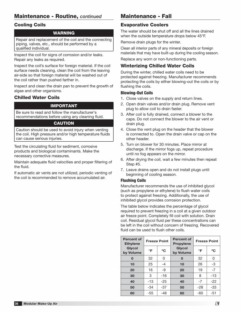
Modular Make-Up Air36®
Maintenance - Fall
Evaporative CoolersThe water should be shut off and all the lines drained when the outside temperature drops below 45°F.
Remove drain plugs for the winter.
Clean all interior parts of any mineral deposits or foreign materials that may have built-up during the cooling season.
Replace any worn or non-functioning parts.
Winterizing Chilled Water CoilsDuring the winter, chilled water coils need to be protected against freezing. Manufacturer recommends protecting the coils by either blowing-out the coils or by flushing the coils.
Blowing-Out Coils1. Close valves on the supply and return lines.2. Open drain valves and/or drain plug. Remove vent
plug to allow coil to drain faster.3. After coil is fully drained, connect a blower to the
caps. Do not connect the blower to the air vent or drain plug.
4. Close the vent plug on the header that the blower is connected to. Open the drain valve or cap on the other header.
5. Turn on blower for 30 minutes. Place mirror at discharge. If the mirror fogs up, repeat procedure until no fog appears on the mirror.
6. After drying the coil, wait a few minutes then repeat Step #5.
7. Leave drains open and do not install plugs until beginning of cooling season.
Flushing CoilsManufacturer recommends the use of inhibited glycol (such as propylene or ethylene) to flush water coils to protect against freezing. Additionally, the use of inhibited glycol provides corrosion protection.
The table below indicates the percentage of glycol required to prevent freezing in a coil at a given outdoor air freeze point. Completely fill coil with solution. Drain coil. Residual glycol fluid per these concentrations can be left in the coil without concern of freezing. Recovered fluid can be used to flush other coils.
Percent of
Ethylene
Glycol
by Volume
Freeze PointPercent of
Propylene
Glycol
by Volume
Freeze Point
°F ºC °F ºC
0 32 0 0 32 0
10 25 -4 10 26 -3
20 16 -9 20 19 -7
30 3 -16 30 8 -13
40 -13 -25 40 -7 -22
50 -34 -37 50 -28 -33
60 -55 -48 60 -60 -51
Cooling Coils
Inspect the coil for signs of corrosion and/or leaks. Repair any leaks as required.
Inspect the coil’s surface for foreign material. If the coil surface needs cleaning, clean the coil from the leaving air-side so that foreign material will be washed out of the coil rather than pushed farther in.
Inspect and clean the drain pan to prevent the growth of algae and other organisms.
Chilled Water Coils
Test the circulating fluid for sediment, corrosive products and biological contaminants. Make the necessary corrective measures.
Maintain adequate fluid velocities and proper filtering of the fluid.
If automatic air vents are not utilized, periodic venting of the coil is recommended to remove accumulated air.
WARNINGRepair and replacement of the coil and the connecting piping, valves, etc., should be performed by a qualified individual.
IMPORTANTBe sure to read and follow the manufacturer’s recommendations before using any cleaning fluid.
CAUTIONCaution should be used to avoid injury when venting the coil. High pressure and/or high temperature fluids can cause serious injuries.
Maintenance - Routine, continued
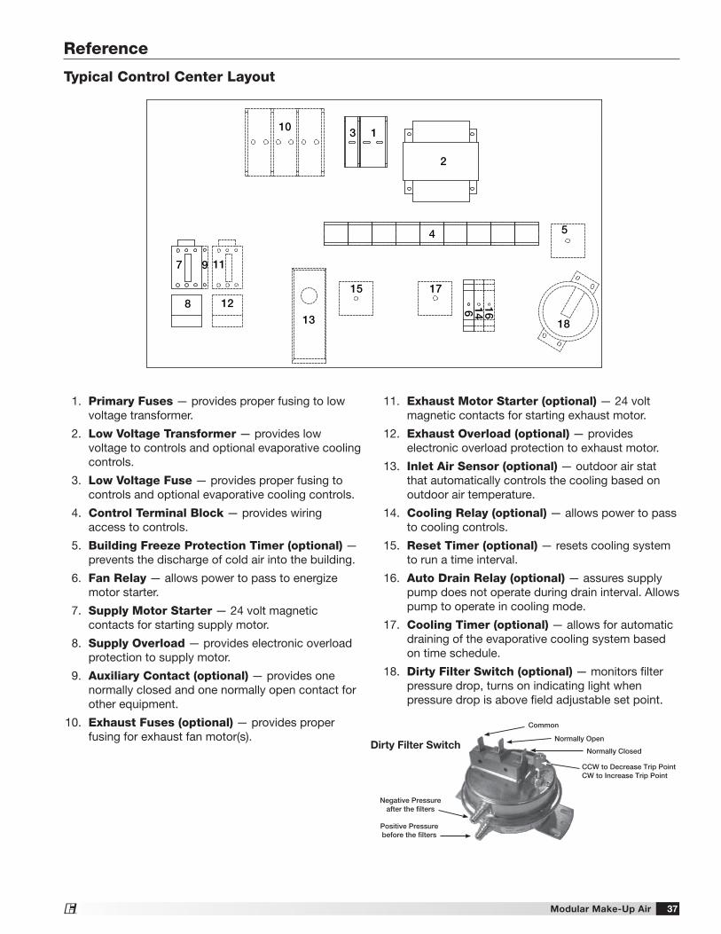
Modular Make-Up Air 37®
Reference
Typical Control Center Layout
7
8
4
69 11
12
10
514
2
13 18
3 1
16
15 17
1. Primary Fuses — provides proper fusing to low voltage transformer.
2. Low Voltage Transformer — provides low voltage to controls and optional evaporative cooling controls.
3. Low Voltage Fuse — provides proper fusing to controls and optional evaporative cooling controls.
4. Control Terminal Block — provides wiring access to controls.
5. Building Freeze Protection Timer (optional) — prevents the discharge of cold air into the building.
6. Fan Relay — allows power to pass to energize motor starter.
7. Supply Motor Starter — 24 volt magnetic contacts for starting supply motor.
8. Supply Overload — provides electronic overload protection to supply motor.
9. Auxiliary Contact (optional) — provides one normally closed and one normally open contact for other equipment.
10. Exhaust Fuses (optional) — provides proper fusing for exhaust fan motor(s).
11. Exhaust Motor Starter (optional) — 24 volt magnetic contacts for starting exhaust motor.
12. Exhaust Overload (optional) — provides electronic overload protection to exhaust motor.
13. Inlet Air Sensor (optional) — outdoor air stat that automatically controls the cooling based on outdoor air temperature.
14. Cooling Relay (optional) — allows power to pass to cooling controls.
15. Reset Timer (optional) — resets cooling system to run a time interval.
16. Auto Drain Relay (optional) — assures supply pump does not operate during drain interval. Allows pump to operate in cooling mode.
17. Cooling Timer (optional) — allows for automatic draining of the evaporative cooling system based on time schedule.
18. Dirty Filter Switch (optional) — monitors filter pressure drop, turns on indicating light when pressure drop is above field adjustable set point.
Dirty Filter Switch
Negative Pressureafter the filters
Common
Normally Open
Normally Closed
CCW to Decrease Trip PointCW to Increase Trip Point
Positive Pressurebefore the filters
Modular Make-Up Air38®
Maintenance Log
Date ___________________Time _____________ AM/PM
Notes: ___________________________________________
_________________________________________________
_________________________________________________
_________________________________________________
_________________________________________________
Date ___________________Time _____________ AM/PM
Notes: ___________________________________________
_________________________________________________
_________________________________________________
_________________________________________________
_________________________________________________
Date ___________________Time _____________ AM/PM
Notes: ___________________________________________
_________________________________________________
_________________________________________________
_________________________________________________
_________________________________________________
Date ___________________Time _____________ AM/PM
Notes: ___________________________________________
_________________________________________________
_________________________________________________
_________________________________________________
_________________________________________________
Date ___________________Time _____________ AM/PM
Notes: ___________________________________________
_________________________________________________
_________________________________________________
_________________________________________________
_________________________________________________
Date ___________________Time _____________ AM/PM
Notes: ___________________________________________
_________________________________________________
_________________________________________________
_________________________________________________
_________________________________________________
Date ___________________Time _____________ AM/PM
Notes: ___________________________________________
_________________________________________________
_________________________________________________
_________________________________________________
_________________________________________________
Date ___________________Time _____________ AM/PM
Notes: ___________________________________________
_________________________________________________
_________________________________________________
_________________________________________________
_________________________________________________
Date ___________________Time _____________ AM/PM
Notes: ___________________________________________
_________________________________________________
_________________________________________________
_________________________________________________
_________________________________________________
Date ___________________Time _____________ AM/PM
Notes: ___________________________________________
_________________________________________________
_________________________________________________
_________________________________________________
_________________________________________________
Date ___________________Time _____________ AM/PM
Notes: ___________________________________________
_________________________________________________
_________________________________________________
_________________________________________________
_________________________________________________
Date ___________________Time _____________ AM/PM
Notes: ___________________________________________
_________________________________________________
_________________________________________________
_________________________________________________
_________________________________________________
Modular Make-Up Air 39®
Maintenance Log
Date ___________________Time _____________ AM/PM
Notes: ___________________________________________
_________________________________________________
_________________________________________________
_________________________________________________
_________________________________________________
Date ___________________Time _____________ AM/PM
Notes: ___________________________________________
_________________________________________________
_________________________________________________
_________________________________________________
_________________________________________________
Date ___________________Time _____________ AM/PM
Notes: ___________________________________________
_________________________________________________
_________________________________________________
_________________________________________________
_________________________________________________
Date ___________________Time _____________ AM/PM
Notes: ___________________________________________
_________________________________________________
_________________________________________________
_________________________________________________
_________________________________________________
Date ___________________Time _____________ AM/PM
Notes: ___________________________________________
_________________________________________________
_________________________________________________
_________________________________________________
_________________________________________________
Date ___________________Time _____________ AM/PM
Notes: ___________________________________________
_________________________________________________
_________________________________________________
_________________________________________________
_________________________________________________
Date ___________________Time _____________ AM/PM
Notes: ___________________________________________
_________________________________________________
_________________________________________________
_________________________________________________
_________________________________________________
Date ___________________Time _____________ AM/PM
Notes: ___________________________________________
_________________________________________________
_________________________________________________
_________________________________________________
_________________________________________________
Date ___________________Time _____________ AM/PM
Notes: ___________________________________________
_________________________________________________
_________________________________________________
_________________________________________________
_________________________________________________
Date ___________________Time _____________ AM/PM
Notes: ___________________________________________
_________________________________________________
_________________________________________________
_________________________________________________
_________________________________________________
Date ___________________Time _____________ AM/PM
Notes: ___________________________________________
_________________________________________________
_________________________________________________
_________________________________________________
_________________________________________________
Date ___________________Time _____________ AM/PM
Notes: ___________________________________________
_________________________________________________
_________________________________________________
_________________________________________________
_________________________________________________
470658 • MSX, Rev. 6, August 2016 Copyright 2016 © Greenheck Fan Corporation40
As a result of our commitment to continuous improvement, Greenheck reserves the right to change specifications without notice.
Specific Greenheck product warranties are located on greenheck.com within the product area tabs and in the Library under Warranties.
Greenheck’s Modular Make-Up Air catalog, Model MSX, provides additional information describing the equipment, fan performance, available accessories, and specification data.
®
Phone: 715.359.6171 • Fax: 715.355.2399 • Parts: 800.355.5354 • E-mail: [email protected] • Website: www.greenheck.com
Our Commitment
AMCA Publication 410-96, Safety Practices for Users and Installers of Industrial and Commercial Fans, provides additional safety information. This publication can be obtained from AMCA International, Inc. at www.amca.org.