heater blower motor kit for range … photos/instructions... · of the unit. (photo 27) part/kit:...
TRANSCRIPT
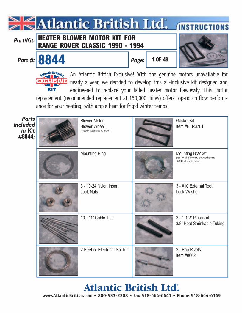
An Atlantic British Exclusive! With the genuine motors unavailable for nearly a year, we decided to develop this all-inclusive kit designed and engineered to replace your failed heater motor flawlessly. This motor
replacement (recommended replacement at 150,000 miles) offers top-notch flow perform-ance for your heating, with ample heat for frigid winter temps!
EXCLUSIVEEXCLUSIVEEXCLUSIVEKITKITKIT
®
Partsincluded
in Kit#8844:
Part/Kit:
Part #: Page:
Blower MotorBlower Wheel (already assembled to motor)
Mounting Ring
3 - 10-24 Nylon Insert Lock Nuts
10 - 11" Cable Ties
2 Feet of Electrical Solder
2 - 1-1/2" Pieces of 3/8" Heat Shrinkable Tubing
3 - #10 External Tooth Lock Washer
Mounting Bracket (has 10-24 x 1 screw, lock washer and 10-24 lock nut included)
Gasket KitItem #BTR3761
2 - Pop Rivets Item #8662
8844
HEATER BLOWER MOTOR KIT FOR RANGE ROVER CLASSIC 1990 - 1994
1 OF 48
www.AtlanticBritish.com • 800-533-2208 • Fax 518-664-6641 • Phone 518-664-6169Atlantic British Ltd. ®
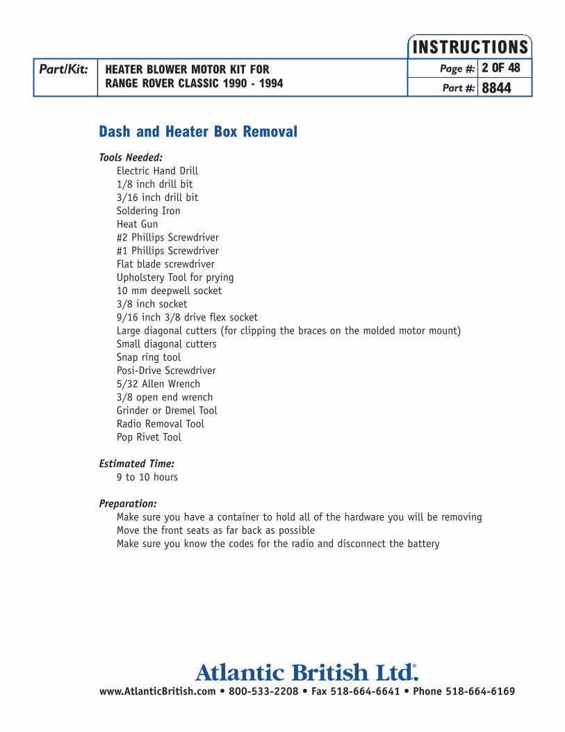
Dash and Heater Box Removal
Tools Needed:Electric Hand Drill1/8 inch drill bit3/16 inch drill bitSoldering IronHeat Gun#2 Phillips Screwdriver#1 Phillips ScrewdriverFlat blade screwdriverUpholstery Tool for prying10 mm deepwell socket3/8 inch socket9/16 inch 3/8 drive flex socketLarge diagonal cutters (for clipping the braces on the molded motor mount)Small diagonal cuttersSnap ring toolPosi-Drive Screwdriver5/32 Allen Wrench3/8 open end wrenchGrinder or Dremel ToolRadio Removal ToolPop Rivet Tool
Estimated Time:9 to 10 hours
Preparation:Make sure you have a container to hold all of the hardware you will be removing Move the front seats as far back as possibleMake sure you know the codes for the radio and disconnect the battery
Part/Kit: HEATER BLOWER MOTOR KIT FORRANGE ROVER CLASSIC 1990 - 1994
Page #: 2 OF 48
Part #: 8844
INSTRUCTIONS
www.AtlanticBritish.com • 800-533-2208 • Fax 518-664-6641 • Phone 518-664-6169Atlantic British Ltd. ®

Procedure:
Door Removal: (Makes working in and around the dash much easier)For the Left (Drivers) side
1. Remove the retaining clip from the top most and bottom most door hinge posts. (See photo 1)
2. Remove the roll pin from the door check bracket (photo 2)
Part/Kit: HEATER BLOWER MOTOR KIT FORRANGE ROVER CLASSIC 1990 - 1994
Page #: 3 OF 48
Part #: 8844
INSTRUCTIONS
(photo 1)
(photo 2)
www.AtlanticBritish.com • 800-533-2208 • Fax 518-664-6641 • Phone 518-664-6169Atlantic British Ltd. ®

3. Remove the foot rest from the left foot-well and remove the 2 push posts to remove thefoot-well kick panel. (See photo 3)
4. Disconnect the connectors for the door electrics (See photo 4, picture is from the right side) and feed through the opening in the frame.
5. Lift the door off of the hinges.6. Repeat for the right hand side. (There will be no foot rest.)
Part/Kit: HEATER BLOWER MOTOR KIT FORRANGE ROVER CLASSIC 1990 - 1994
Page #: 4 OF 48
Part #: 8844
INSTRUCTIONS
www.AtlanticBritish.com • 800-533-2208 • Fax 518-664-6641 • Phone 518-664-6169Atlantic British Ltd. ®
(photo 3)
(photo 4)

Lower Left Foot-Well Panel removal:
1. Pop out the louver to the left of the steering column. (photo 5)
2. Remove the left fascia by taking the 2 screws out shown in photo 6.
3. Remove the 8 screws securing the panel. (See photos 7, 8, and 9)
Part/Kit: HEATER BLOWER MOTOR KIT FORRANGE ROVER CLASSIC 1990 - 1994
Page #: 5 OF 48
Part #: 8844
INSTRUCTIONS
www.AtlanticBritish.com • 800-533-2208 • Fax 518-664-6641 • Phone 518-664-6169Atlantic British Ltd. ®
(photo 5)
(photo 8)
(photo 7) (photo 9)
(photo 6)
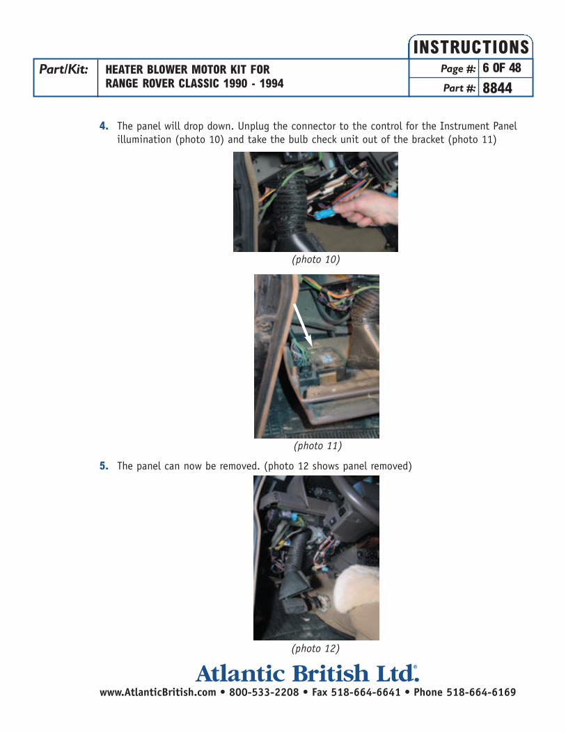
4. The panel will drop down. Unplug the connector to the control for the Instrument Panel illumination (photo 10) and take the bulb check unit out of the bracket (photo 11)
5. The panel can now be removed. (photo 12 shows panel removed)
Part/Kit: HEATER BLOWER MOTOR KIT FORRANGE ROVER CLASSIC 1990 - 1994
Page #: 6 OF 48
Part #: 8844
INSTRUCTIONS
www.AtlanticBritish.com • 800-533-2208 • Fax 518-664-6641 • Phone 518-664-6169Atlantic British Ltd. ®
(photo 10)
(photo 11)
(photo 12)
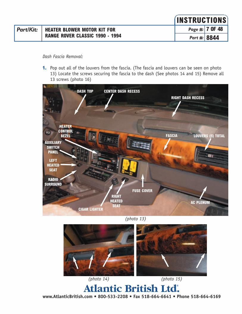
Dash Fascia Removal:
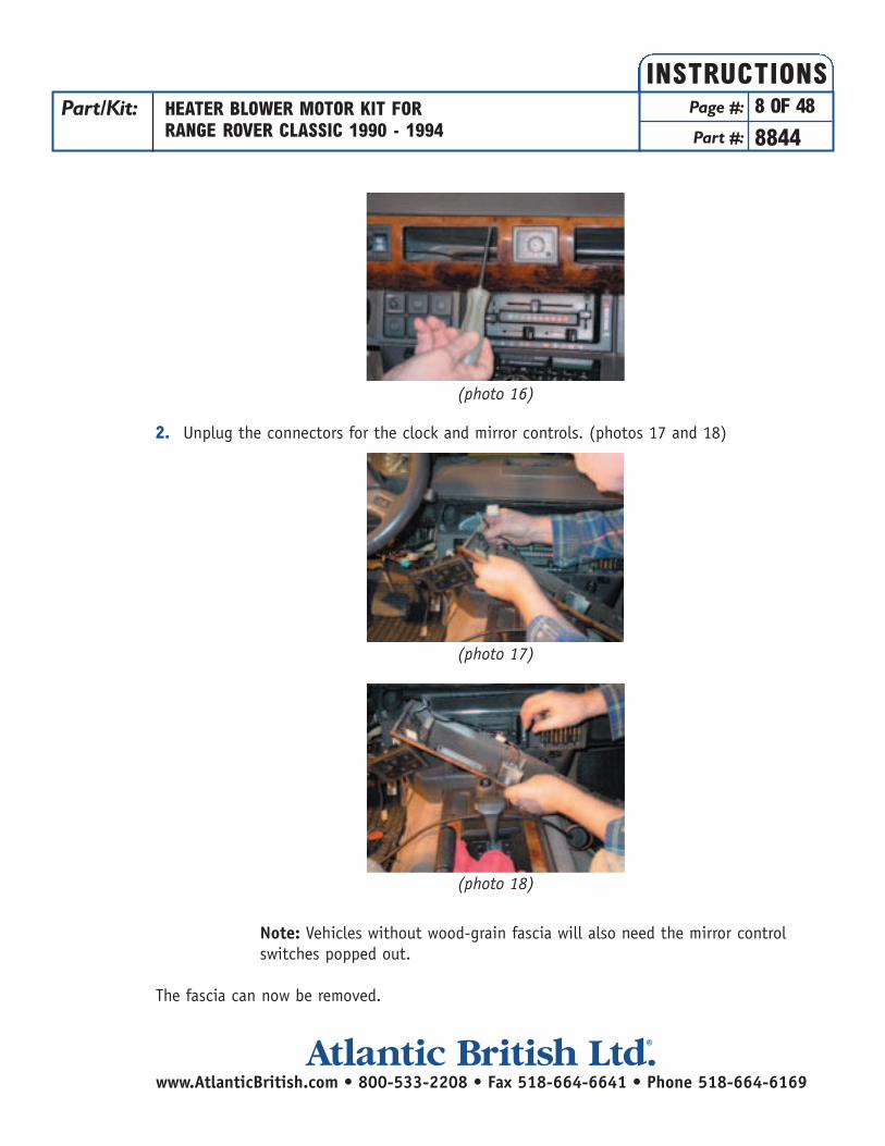
1. Pop out all of the louvers from the fascia. (The fascia and louvers can be seen on photo 13) Locate the screws securing the fascia to the dash (See photos 14 and 15) Remove all 13 screws (photo 16)
Part/Kit: HEATER BLOWER MOTOR KIT FORRANGE ROVER CLASSIC 1990 - 1994
Page #: 7 OF 48
Part #: 8844
INSTRUCTIONS
www.AtlanticBritish.com • 800-533-2208 • Fax 518-664-6641 • Phone 518-664-6169Atlantic British Ltd. ®
(photo 14) (photo 15)
(photo 13)
DASH TOP CENTER DASH RECESS
RIGHT DASH RECESS
FASCIA
AC PLENUM
FUSE COVERRIGHT
HEATEDSEAT
LEFTHEATEDSEAT
CIGAR LIGHTER
HEATERCONTROLBEZEL
AUXILIARYSWITCHPANEL
RADIOSURROUND
LOUVERS (5) TOTAL
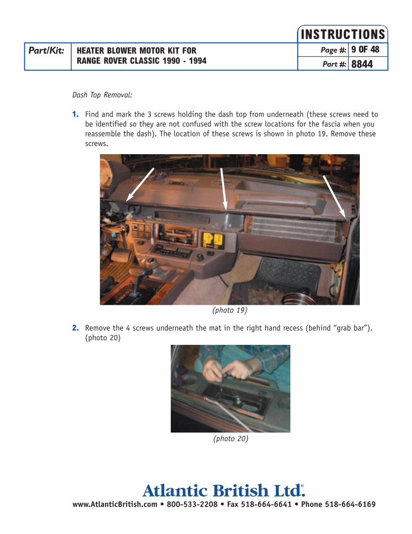
2. Unplug the connectors for the clock and mirror controls. (photos 17 and 18)
Note: Vehicles without wood-grain fascia will also need the mirror control switches popped out.
The fascia can now be removed.
Part/Kit: HEATER BLOWER MOTOR KIT FORRANGE ROVER CLASSIC 1990 - 1994
Page #: 8 OF 48
Part #: 8844
INSTRUCTIONS
www.AtlanticBritish.com • 800-533-2208 • Fax 518-664-6641 • Phone 518-664-6169Atlantic British Ltd. ®
(photo 16)
(photo 17)
(photo 18)
Dash Top Removal:
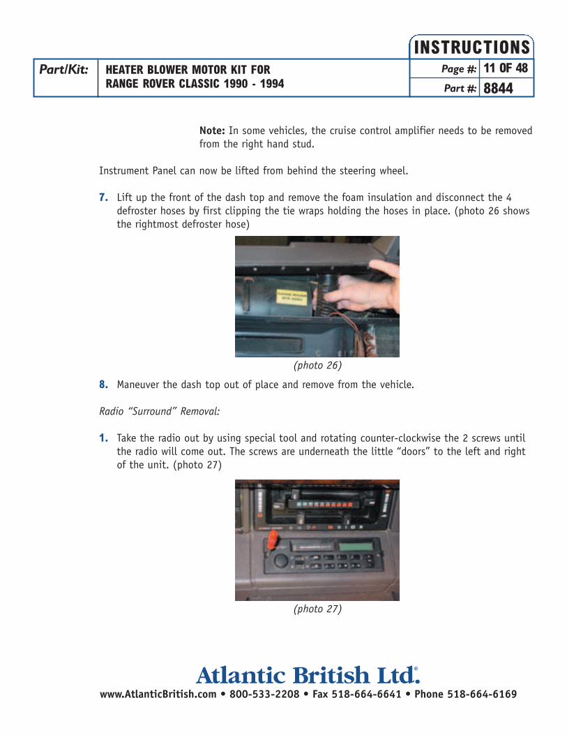
1. Find and mark the 3 screws holding the dash top from underneath (these screws need tobe identified so they are not confused with the screw locations for the fascia when you reassemble the dash). The location of these screws is shown in photo 19. Remove these screws.
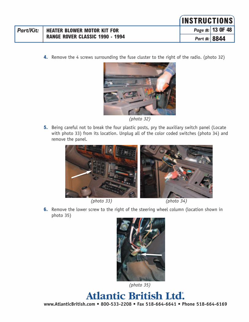
2. Remove the 4 screws underneath the mat in the right hand recess (behind “grab bar”). (photo 20)
Part/Kit: HEATER BLOWER MOTOR KIT FORRANGE ROVER CLASSIC 1990 - 1994
Page #: 9 OF 48
Part #: 8844
INSTRUCTIONS
www.AtlanticBritish.com • 800-533-2208 • Fax 518-664-6641 • Phone 518-664-6169Atlantic British Ltd. ®
(photo 19)
(photo 20)

3. Remove the 4 screws underneath the mat in the center of the dash. This tray will lift up and you can unplug the connector to the alarm LED. Remove this tray. (photo 21 and 22)
Remove the Instrument Panel by:4. Snap off the hood covering the rear of the panel5. Unplug the 3 connectors from the back of the instrument panel (shown in photo 23).
6. Remove the 4 nuts/washers securing the instrument panel from underneath the dash. (location shown in photos 24 & 25)
Part/Kit: HEATER BLOWER MOTOR KIT FORRANGE ROVER CLASSIC 1990 - 1994
Page #: 10 OF 48
Part #: 8844
INSTRUCTIONS
www.AtlanticBritish.com • 800-533-2208 • Fax 518-664-6641 • Phone 518-664-6169Atlantic British Ltd. ®
(photo 21) (photo 22)
(photo 24) (photo 25)
(photo 23)
Note: In some vehicles, the cruise control amplifier needs to be removedfrom the right hand stud.
Instrument Panel can now be lifted from behind the steering wheel.
7. Lift up the front of the dash top and remove the foam insulation and disconnect the 4 defroster hoses by first clipping the tie wraps holding the hoses in place. (photo 26 shows the rightmost defroster hose)
8. Maneuver the dash top out of place and remove from the vehicle.
Radio “Surround” Removal:
1. Take the radio out by using special tool and rotating counter-clockwise the 2 screws until the radio will come out. The screws are underneath the little “doors” to the left and right of the unit. (photo 27)
Part/Kit: HEATER BLOWER MOTOR KIT FORRANGE ROVER CLASSIC 1990 - 1994
Page #: 11 OF 48
Part #: 8844
INSTRUCTIONS
www.AtlanticBritish.com • 800-533-2208 • Fax 518-664-6641 • Phone 518-664-6169Atlantic British Ltd. ®
(photo 26)
(photo 27)

2. Lift the radio out and unplug all of the connectors. Since the connectors for the speakers can be interchanged, you will need to take careful notes about the locations of these connectors. (photo 28)
3. Remove the heater control knobs (photo 29) and the 2 screws holding the panel in place (photo 30). Pull the panel down and unplug the 4 lamp connectors (photo 31). Remove the heater bezel from the vehicle.
Part/Kit: HEATER BLOWER MOTOR KIT FORRANGE ROVER CLASSIC 1990 - 1994
Page #: 12 OF 48
Part #: 8844
INSTRUCTIONS
www.AtlanticBritish.com • 800-533-2208 • Fax 518-664-6641 • Phone 518-664-6169Atlantic British Ltd. ®
(photo 28)
(photo 31)
(photo 29) (photo 30)
4. Remove the 4 screws surrounding the fuse cluster to the right of the radio. (photo 32)
5. Being careful not to break the four plastic posts, pry the auxiliary switch panel (Locate with photo 33) from its location. Unplug all of the color coded switches (photo 34) and remove the panel.
6. Remove the lower screw to the right of the steering wheel column (location shown in photo 35)
Part/Kit: HEATER BLOWER MOTOR KIT FORRANGE ROVER CLASSIC 1990 - 1994
Page #: 13 OF 48
Part #: 8844
INSTRUCTIONS
(photo 32)
(photo 35)
(photo 33) (photo 34)
www.AtlanticBritish.com • 800-533-2208 • Fax 518-664-6641 • Phone 518-664-6169Atlantic British Ltd. ®
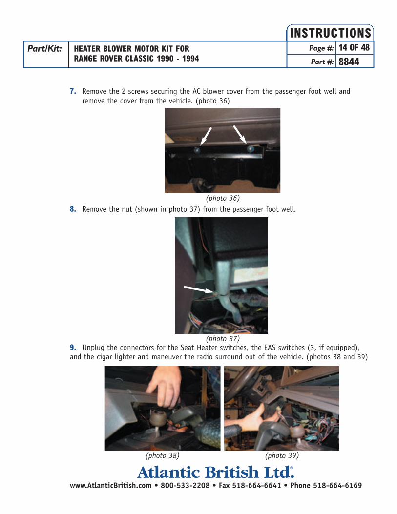
7. Remove the 2 screws securing the AC blower cover from the passenger foot well and remove the cover from the vehicle. (photo 36)
8. Remove the nut (shown in photo 37) from the passenger foot well.
9. Unplug the connectors for the Seat Heater switches, the EAS switches (3, if equipped),and the cigar lighter and maneuver the radio surround out of the vehicle. (photos 38 and 39)
Part/Kit: HEATER BLOWER MOTOR KIT FORRANGE ROVER CLASSIC 1990 - 1994
Page #: 14 OF 48
Part #: 8844
INSTRUCTIONS
www.AtlanticBritish.com • 800-533-2208 • Fax 518-664-6641 • Phone 518-664-6169Atlantic British Ltd. ®
(photo 36)
(photo 37)
(photo 38) (photo 39)

Heater Box Removal:
1. Unplug the connectors from the back of the heater controls. (Shown in photo 40) Make sure to take note of the connector (it is easiest to just mark one of the connectors) locations so they are not interchanged during reassembly.
2. Unplug the Green & Black wires from the recirculation flap solenoid and disconnect the vacuum hose. (Shown in photo 41)
Part/Kit: HEATER BLOWER MOTOR KIT FORRANGE ROVER CLASSIC 1990 - 1994
Page #: 15 OF 48
Part #: 8844
INSTRUCTIONS
www.AtlanticBritish.com • 800-533-2208 • Fax 518-664-6641 • Phone 518-664-6169Atlantic British Ltd. ®
(photo 40)
(photo 41)
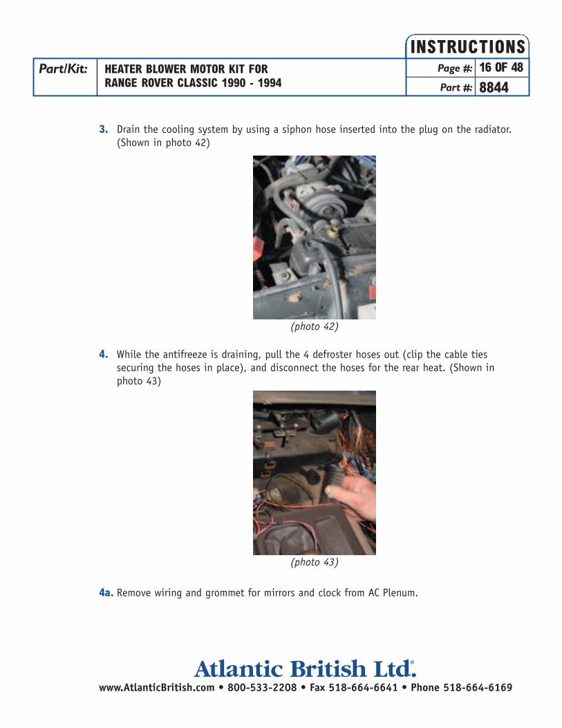
3. Drain the cooling system by using a siphon hose inserted into the plug on the radiator. (Shown in photo 42)
4. While the antifreeze is draining, pull the 4 defroster hoses out (clip the cable ties securing the hoses in place), and disconnect the hoses for the rear heat. (Shown in photo 43)
4a. Remove wiring and grommet for mirrors and clock from AC Plenum.
Part/Kit: HEATER BLOWER MOTOR KIT FORRANGE ROVER CLASSIC 1990 - 1994
Page #: 16 OF 48
Part #: 8844
INSTRUCTIONS
www.AtlanticBritish.com • 800-533-2208 • Fax 518-664-6641 • Phone 518-664-6169Atlantic British Ltd. ®
(photo 42)
(photo 43)
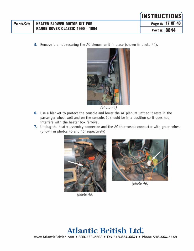
5. Remove the nut securing the AC plenum unit in place (shown in photo 44).
6. Use a blanket to protect the console and lower the AC plenum unit so it rests in the passenger wheel well and on the console. It should be in a position so it does not interfere with the heater box removal.
7. Unplug the heater assembly connector and the AC thermostat connector with green wires. (Shown in photos 45 and 46 respectively)
Part/Kit: HEATER BLOWER MOTOR KIT FORRANGE ROVER CLASSIC 1990 - 1994
Page #: 17 OF 48
Part #: 8844
INSTRUCTIONS
www.AtlanticBritish.com • 800-533-2208 • Fax 518-664-6641 • Phone 518-664-6169Atlantic British Ltd. ®
(photo 44)
(photo 45)
(photo 46)
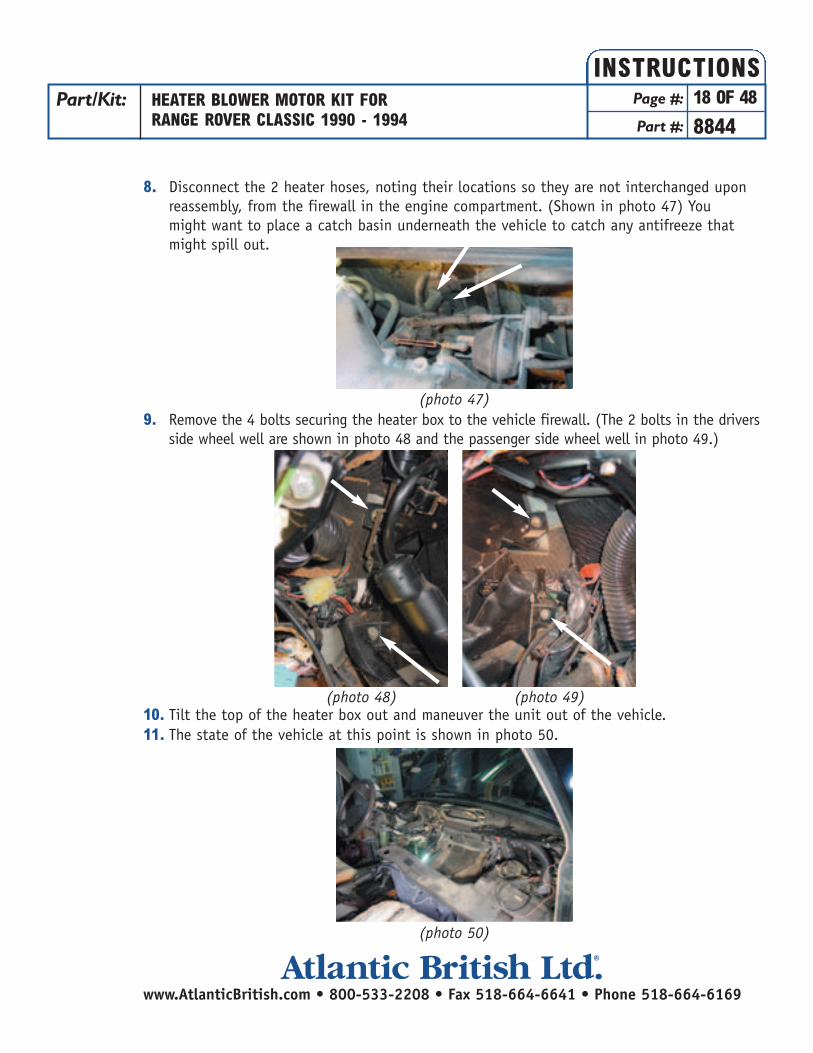
8. Disconnect the 2 heater hoses, noting their locations so they are not interchanged upon reassembly, from the firewall in the engine compartment. (Shown in photo 47) You might want to place a catch basin underneath the vehicle to catch any antifreeze that might spill out.
9. Remove the 4 bolts securing the heater box to the vehicle firewall. (The 2 bolts in the drivers side wheel well are shown in photo 48 and the passenger side wheel well in photo 49.)
10. Tilt the top of the heater box out and maneuver the unit out of the vehicle.11. The state of the vehicle at this point is shown in photo 50.
Part/Kit: HEATER BLOWER MOTOR KIT FORRANGE ROVER CLASSIC 1990 - 1994
Page #: 18 OF 48
Part #: 8844
INSTRUCTIONS
www.AtlanticBritish.com • 800-533-2208 • Fax 518-664-6641 • Phone 518-664-6169Atlantic British Ltd. ®
(photo 47)
(photo 50)
(photo 48) (photo 49)

Heater Box Rebuild
1. Remove the right and left plastic footwell ducts. (shown after removal in photo 51)
2. Remove the gaskets surrounding the fresh air inlet and the blower output. (See photos 52 and 53)
3. Drill out the 2 rivets on the left half of the heater enclosure holding the heater control assembly to the plastic heater housing with a 3/16 inch drill bit. (See photos 54 and 55)
Part/Kit: HEATER BLOWER MOTOR KIT FORRANGE ROVER CLASSIC 1990 - 1994
Page #: 19 OF 48
Part #: 8844
INSTRUCTIONS
www.AtlanticBritish.com • 800-533-2208 • Fax 518-664-6641 • Phone 518-664-6169Atlantic British Ltd. ®
(photo 51)
(photo 52) (photo 53)
(photo 54) (photo 55)
VENT OUTLETINLET
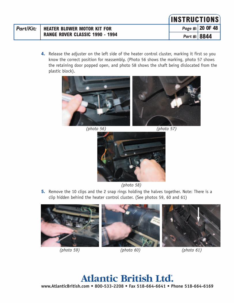
4. Release the adjuster on the left side of the heater control cluster, marking it first so you know the correct position for reassembly. (Photo 56 shows the marking, photo 57 shows the retaining door popped open, and photo 58 shows the shaft being dislocated from the plastic block).
5. Remove the 10 clips and the 2 snap rings holding the halves together. Note: There is a clip hidden behind the heater control cluster. (See photos 59, 60 and 61)
Part/Kit: HEATER BLOWER MOTOR KIT FORRANGE ROVER CLASSIC 1990 - 1994
Page #: 20 OF 48
Part #: 8844
INSTRUCTIONS
www.AtlanticBritish.com • 800-533-2208 • Fax 518-664-6641 • Phone 518-664-6169Atlantic British Ltd. ®
(photo 56) (photo 57)
(photo 58)
(photo 60)(photo 59) (photo 61)
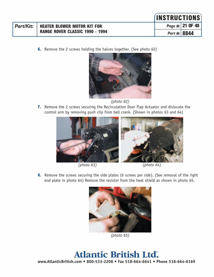
6. Remove the 2 screws holding the halves together. (See photo 62)
7. Remove the 2 screws securing the Recirculation Door Flap Actuator and dislocate the control arm by removing push clip from bell crank. (Shown in photos 63 and 64)
8. Remove the screws securing the side plates (6 screws per side). (See removal of the right end plate in photo 64) Remove the resistor from the heat shield as shown in photo 65.
Part/Kit: HEATER BLOWER MOTOR KIT FORRANGE ROVER CLASSIC 1990 - 1994
Page #: 21 OF 48
Part #: 8844
INSTRUCTIONS
www.AtlanticBritish.com • 800-533-2208 • Fax 518-664-6641 • Phone 518-664-6169Atlantic British Ltd. ®
(photo 62)
(photo 65)
(photo 63) (photo 64)

9. CRITICAL STEP: Move the Fresh Air Flap fully closed and pry it so that it lines up with the “V” shaped opening in the right half of the unit. (The “V” is shown in photo 66, and prying techniques are shown in photos 67 and 68) If the flap is not in line with the “V” channel, the halves will not come apart, and you risk damaging the flap.
10. Slide the halves of the heater box apart.11. Remove the foam gasket around the 2 heater core pipes and remove the top flap. (See
photo 69)
12. You can now slide the heater core out of the housing. (See photo 70)
Part/Kit: HEATER BLOWER MOTOR KIT FORRANGE ROVER CLASSIC 1990 - 1994
Page #: 22 OF 48
Part #: 8844
INSTRUCTIONS
www.AtlanticBritish.com • 800-533-2208 • Fax 518-664-6641 • Phone 518-664-6169Atlantic British Ltd. ®
(photo 67)(photo 66) (photo 68)
(photo 69)
(photo 70)
FLAP
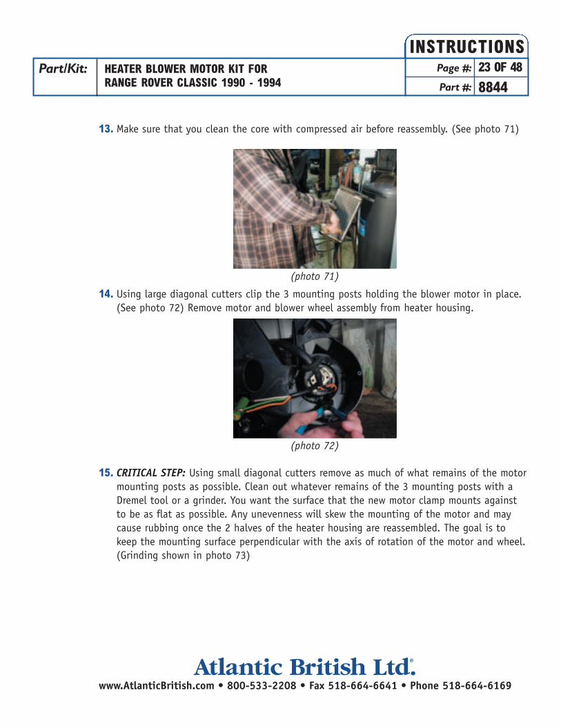
13. Make sure that you clean the core with compressed air before reassembly. (See photo 71)
14. Using large diagonal cutters clip the 3 mounting posts holding the blower motor in place. (See photo 72) Remove motor and blower wheel assembly from heater housing.
15. CRITICAL STEP: Using small diagonal cutters remove as much of what remains of the motor mounting posts as possible. Clean out whatever remains of the 3 mounting posts with a Dremel tool or a grinder. You want the surface that the new motor clamp mounts against to be as flat as possible. Any unevenness will skew the mounting of the motor and may cause rubbing once the 2 halves of the heater housing are reassembled. The goal is to keep the mounting surface perpendicular with the axis of rotation of the motor and wheel. (Grinding shown in photo 73)
Part/Kit: HEATER BLOWER MOTOR KIT FORRANGE ROVER CLASSIC 1990 - 1994
Page #: 23 OF 48
Part #: 8844
INSTRUCTIONS
www.AtlanticBritish.com • 800-533-2208 • Fax 518-664-6641 • Phone 518-664-6169Atlantic British Ltd. ®
(photo 71)
(photo 72)
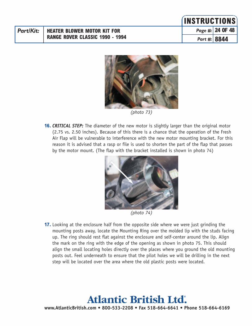
16. CRITICAL STEP: The diameter of the new motor is slightly larger than the original motor (2.75 vs. 2.50 inches). Because of this there is a chance that the operation of the Fresh Air Flap will be vulnerable to interference with the new motor mounting bracket. For this reason it is advised that a rasp or file is used to shorten the part of the flap that passes by the motor mount. (The flap with the bracket installed is shown in photo 74)
17. Looking at the enclosure half from the opposite side where we were just grinding the mounting posts away, locate the Mounting Ring over the molded lip with the studs facing up. The ring should rest flat against the enclosure and self-center around the lip. Align the mark on the ring with the edge of the opening as shown in photo 75. This should align the small locating holes directly over the places where you ground the old mounting posts out. Feel underneath to ensure that the pilot holes we will be drilling in the next step will be located over the area where the old plastic posts were located.
Part/Kit: HEATER BLOWER MOTOR KIT FORRANGE ROVER CLASSIC 1990 - 1994
Page #: 24 OF 48
Part #: 8844
INSTRUCTIONS
www.AtlanticBritish.com • 800-533-2208 • Fax 518-664-6641 • Phone 518-664-6169Atlantic British Ltd. ®
(photo 73)
(photo 74)

18. Being very careful not to move the ring, use a 1/8 inch drill to drill pilot holes through the 3 holes in the ring and through the plastic of the enclosure. (See photo 76)
19. Enlarge the holes drilled in the last step with a 3/16 inch drill bit. Flip the Mounting Ring over and press the studs through the holes you just enlarged. It will be a tight fit so that the ring stays in place as we turn the enclosure over and install the Motor Mounting Clamp. (See photo 77)
Part/Kit: HEATER BLOWER MOTOR KIT FORRANGE ROVER CLASSIC 1990 - 1994
Page #: 25 OF 48
Part #: 8844
INSTRUCTIONS
www.AtlanticBritish.com • 800-533-2208 • Fax 518-664-6641 • Phone 518-664-6169Atlantic British Ltd. ®
(photo 75)
(photo 76)
(photo 77)

20. Turn the enclosure over and install the Motor Mounting Clamp as shown in photo 78, allowing access to the tightening nut. Install the external tooth lock washers over the studs and loosely tighten the nylon insert locknuts on the studs (We will tighten these in a later step.)
21. Clip the Black and Red wires from the old motor (See photo 79). Feed these wires through the enclosure between the space between the Motor Mounting Clamp and the blower wheel opening. (See photo 80)
22. Pulling the wires though the enclosure so that you have adequate slack solder these wires to the wires on the motor matching the colors. Make sure to slip the heat-shrinkable tubing over the wires before you solder them. (See photo 81). It is important that the wires are soldered and not crimped together. The vibration that this unit is likely to see will cause a crimped connection to eventually fail. You would not want to repeat this entire procedure just to fix a bad connection.
Part/Kit: HEATER BLOWER MOTOR KIT FORRANGE ROVER CLASSIC 1990 - 1994
Page #: 26 OF 48
Part #: 8844
INSTRUCTIONS
www.AtlanticBritish.com • 800-533-2208 • Fax 518-664-6641 • Phone 518-664-6169Atlantic British Ltd. ®
(photo 78)
(photo 79) (photo 80)
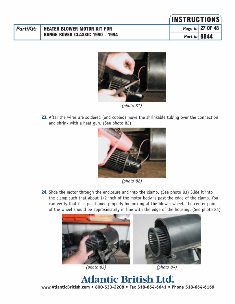
23. After the wires are soldered (and cooled) move the shrinkable tubing over the connection and shrink with a heat gun. (See photo 82)
24. Slide the motor through the enclosure and into the clamp. (See photo 83) Slide it into the clamp such that about 1/2 inch of the motor body is past the edge of the clamp. You can verify that it is positioned properly by looking at the blower wheel. The center point of the wheel should be approximately in line with the edge of the housing. (See photo 84)
Part/Kit: HEATER BLOWER MOTOR KIT FORRANGE ROVER CLASSIC 1990 - 1994
Page #: 27 OF 48
Part #: 8844
INSTRUCTIONS
www.AtlanticBritish.com • 800-533-2208 • Fax 518-664-6641 • Phone 518-664-6169Atlantic British Ltd. ®
(photo 81)
(photo 82)
(photo 83) (photo 84)

25. Using a thin walled 3/8 socket and 5/32 Allen Wrench tighten the motor clamp nut andthe 3 nuts securing the clamp to the enclosure. (See photos 85 and 86)
26. Reinstall the heater core and the heater core panel.27. Lining all of the flaps back up, slide the halves back together making sure that the fresh
air flap is lined up with the “V” in the housing like you did during disassembly. This step requires a little patience. Using a pick can help in guiding the shafts into their locations in the enclosure. (See photos 87, 88, and 89) It may be necessary to remove the defrost ducts to get at the shaft openings. (See photos 90 and 91)
Part/Kit: HEATER BLOWER MOTOR KIT FORRANGE ROVER CLASSIC 1990 - 1994
Page #: 28 OF 48
Part #: 8844
INSTRUCTIONS
www.AtlanticBritish.com • 800-533-2208 • Fax 518-664-6641 • Phone 518-664-6169Atlantic British Ltd. ®
(photo 85) (photo 86)
(photo 88)(photo 87)
(photo 89)
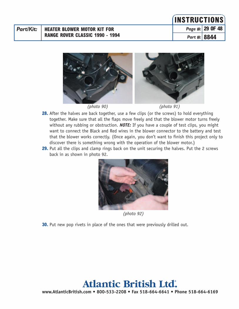
28. After the halves are back together, use a few clips (or the screws) to hold everything together. Make sure that all the flaps move freely and that the blower motor turns freely without any rubbing or obstruction. NOTE: If you have a couple of test clips, you might want to connect the Black and Red wires in the blower connector to the battery and test that the blower works correctly. {Once again, you don’t want to finish this project only to discover there is something wrong with the operation of the blower motor.}
29. Put all the clips and clamp rings back on the unit securing the halves. Put the 2 screws back in as shown in photo 92.
30. Put new pop rivets in place of the ones that were previously drilled out.
(photo 90) (photo 91)
Part/Kit: HEATER BLOWER MOTOR KIT FORRANGE ROVER CLASSIC 1990 - 1994
Page #: 29 OF 48
Part #: 8844
INSTRUCTIONS
www.AtlanticBritish.com • 800-533-2208 • Fax 518-664-6641 • Phone 518-664-6169Atlantic British Ltd. ®
(photo 92)
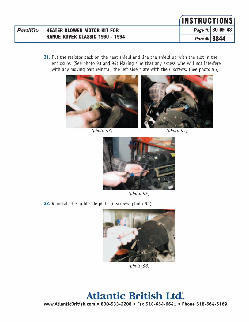
31. Put the resistor back on the heat shield and line the shield up with the slot in the enclosure. (See photo 93 and 94) Making sure that any excess wire will not interfere with any moving part reinstall the left side plate with the 6 screws. (See photo 95)
32. Reinstall the right side plate (6 screws, photo 96)
Part/Kit: HEATER BLOWER MOTOR KIT FORRANGE ROVER CLASSIC 1990 - 1994
Page #: 30 OF 48
Part #: 8844
INSTRUCTIONS
www.AtlanticBritish.com • 800-533-2208 • Fax 518-664-6641 • Phone 518-664-6169Atlantic British Ltd. ®
(photo 93) (photo 94)
(photo 95)
(photo 96)
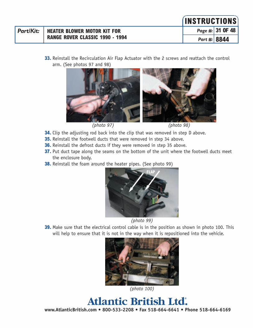
33. Reinstall the Recirculation Air Flap Actuator with the 2 screws and reattach the control arm. (See photos 97 and 98)
34. Clip the adjusting rod back into the clip that was removed in step D above.35. Reinstall the footwell ducts that were removed in step 34 above.36. Reinstall the defrost ducts if they were removed in step 35 above.37. Put duct tape along the seams on the bottom of the unit where the footwell ducts meet
the enclosure body. 38. Reinstall the foam around the heater pipes. (See photo 99)
39. Make sure that the electrical control cable is in the position as shown in photo 100. This will help to ensure that it is not in the way when it is repositioned into the vehicle.
Part/Kit: HEATER BLOWER MOTOR KIT FORRANGE ROVER CLASSIC 1990 - 1994
Page #: 31 OF 48
Part #: 8844
INSTRUCTIONS
www.AtlanticBritish.com • 800-533-2208 • Fax 518-664-6641 • Phone 518-664-6169Atlantic British Ltd. ®
(photo 97) (photo 98)
(photo 99)
(photo 100)
FLAP

Dash & Heater Box Reassembly
Reinstalling the Heater Box:
1. Start with the heater box as shown in photo 101. Then roll the box downward until theheater core pipes line up with the openings in the firewall. See photo 102. Make sure that nocables are inadvertently wrapped around the heater pipes.
2. Bolt the heater box into position with the 4 large bolts shown in photos 103 and 104).
3. Install the connector to the recirculation control and reattach the vacuum hose. (See photos 105 and 106)
Part/Kit: HEATER BLOWER MOTOR KIT FORRANGE ROVER CLASSIC 1990 - 1994
Page #: 32 OF 48
Part #: 8844
INSTRUCTIONS
www.AtlanticBritish.com • 800-533-2208 • Fax 518-664-6641 • Phone 518-664-6169Atlantic British Ltd. ®
(photo 101) (photo 102)
(photo 103) (photo 104)
(photo 105) (photo 106)

4. Install the connector for the heater controls (photo 107)
5. Connect the 2 outboard heater defrost hoses and secure with a cable tie. (See photos 108and 109)
6. Connect the 2 inboard defrost hoses to the dash top and secure with cable ties. (See photo 110)
Part/Kit: HEATER BLOWER MOTOR KIT FORRANGE ROVER CLASSIC 1990 - 1994
Page #: 33 OF 48
Part #: 8844
INSTRUCTIONS
www.AtlanticBritish.com • 800-533-2208 • Fax 518-664-6641 • Phone 518-664-6169Atlantic British Ltd. ®
(photo 107)
(photo 110)
(photo 108) (photo 109)

7. Reattach the 2 rear heat hoses. (See photos 111 and 112)
Reinstalling the Dash Top:
1. Reconnect the AC thermostat connector. (photo 113)
2. Maneuver the AC plenum into position making sure to feed the wires for the mirror control and clock through the opening. (See photos 114 and 115)
Part/Kit: HEATER BLOWER MOTOR KIT FORRANGE ROVER CLASSIC 1990 - 1994
Page #: 34 OF 48
Part #: 8844
INSTRUCTIONS
www.AtlanticBritish.com • 800-533-2208 • Fax 518-664-6641 • Phone 518-664-6169Atlantic British Ltd. ®
(photo 111) (photo 112)
(photo 114) (photo 115)
(photo 113)
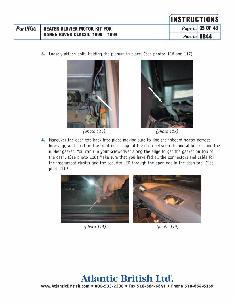
3. Loosely attach bolts holding the plenum in place. (See photos 116 and 117)
4. Maneuver the dash top back into place making sure to line the inboard heater defrost hoses up, and position the front-most edge of the dash between the metal bracket and the rubber gasket. You can run your screwdriver along the edge to get the gasket on top of the dash. (See photo 118) Make sure that you have fed all the connectors and cable for the instrument cluster and the security LED through the openings in the dash top. (See photo 119)
Part/Kit: HEATER BLOWER MOTOR KIT FORRANGE ROVER CLASSIC 1990 - 1994
Page #: 35 OF 48
Part #: 8844
INSTRUCTIONS
www.AtlanticBritish.com • 800-533-2208 • Fax 518-664-6641 • Phone 518-664-6169Atlantic British Ltd. ®
(photo 116) (photo 117)
(photo 118) (photo 119)
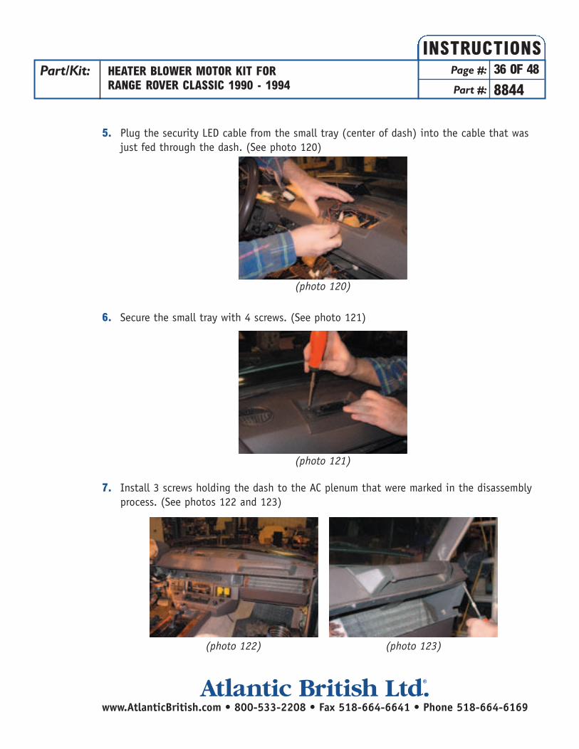
5. Plug the security LED cable from the small tray (center of dash) into the cable that was just fed through the dash. (See photo 120)
6. Secure the small tray with 4 screws. (See photo 121)
7. Install 3 screws holding the dash to the AC plenum that were marked in the disassembly process. (See photos 122 and 123)
Part/Kit: HEATER BLOWER MOTOR KIT FORRANGE ROVER CLASSIC 1990 - 1994
Page #: 36 OF 48
Part #: 8844
INSTRUCTIONS
www.AtlanticBritish.com • 800-533-2208 • Fax 518-664-6641 • Phone 518-664-6169Atlantic British Ltd. ®
(photo 120)
(photo 121)
(photo 122) (photo 123)

8. Loosely install the 4 screws in the dash recess behind the grab bar on the right side of thedash. (See photo 124)
Reinstalling the Instrument Cluster:
1. Position the instrument cluster behind the steering wheel making sure that the 3 connectors feed through the frame. (See photo 125)
Part/Kit: HEATER BLOWER MOTOR KIT FORRANGE ROVER CLASSIC 1990 - 1994
Page #: 37 OF 48
Part #: 8844
INSTRUCTIONS
www.AtlanticBritish.com • 800-533-2208 • Fax 518-664-6641 • Phone 518-664-6169Atlantic British Ltd. ®
(photo 124)
(photo 125)

2. Loosely secure the 4 nuts holding the instrument cluster in place. (See photos 126 and 127) (These nuts will be tightened in a subsequent step.)
Reinstalling the Radio Surround:
1. Position the Radio Surround “roughly” into place while you feed all of the various cables through the openings in the surround. (See photo 128)
2. Reconnect the fuse box with 4 screws. (See photo 129)
Part/Kit: HEATER BLOWER MOTOR KIT FORRANGE ROVER CLASSIC 1990 - 1994
Page #: 38 OF 48
Part #: 8844
INSTRUCTIONS
www.AtlanticBritish.com • 800-533-2208 • Fax 518-664-6641 • Phone 518-664-6169Atlantic British Ltd. ®
(photo 126)
(photo 127)
(photo 128)
(photo 129)
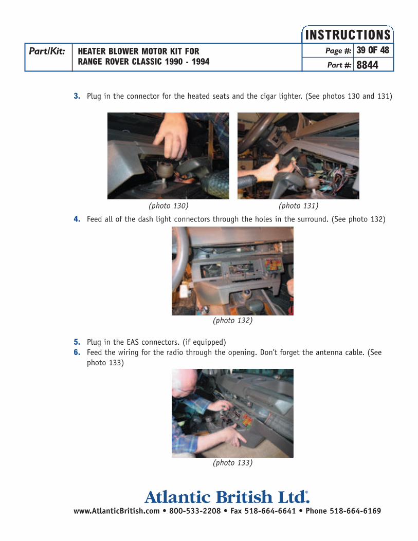
3. Plug in the connector for the heated seats and the cigar lighter. (See photos 130 and 131)
4. Feed all of the dash light connectors through the holes in the surround. (See photo 132)
5. Plug in the EAS connectors. (if equipped)6. Feed the wiring for the radio through the opening. Don’t forget the antenna cable. (See
photo 133)
Part/Kit: HEATER BLOWER MOTOR KIT FORRANGE ROVER CLASSIC 1990 - 1994
Page #: 39 OF 48
Part #: 8844
INSTRUCTIONS
www.AtlanticBritish.com • 800-533-2208 • Fax 518-664-6641 • Phone 518-664-6169Atlantic British Ltd. ®
(photo 130) (photo 131)
(photo 132)
(photo 133)

7. Maneuver the surround over the heater control levers and secure with the nut and washer on the right side (photo 134) and the screw and washer on the left side (photo 135)
Final Assembly:
1. Install the screw over the fuses (photo 136) This will hold everything in place as you proceed.
Part/Kit: HEATER BLOWER MOTOR KIT FORRANGE ROVER CLASSIC 1990 - 1994
Page #: 40 OF 48
Part #: 8844
INSTRUCTIONS
www.AtlanticBritish.com • 800-533-2208 • Fax 518-664-6641 • Phone 518-664-6169Atlantic British Ltd. ®
(photo 134)
(photo 135)
(photo 136)
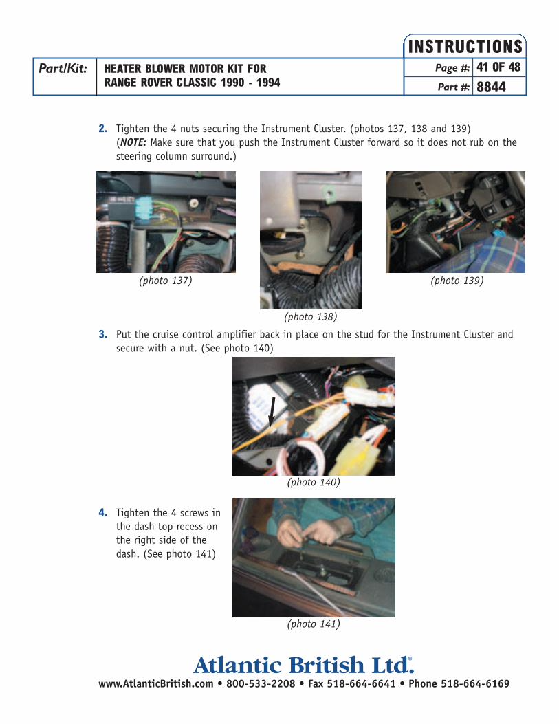
2. Tighten the 4 nuts securing the Instrument Cluster. (photos 137, 138 and 139) (NOTE: Make sure that you push the Instrument Cluster forward so it does not rub on the steering column surround.)
3. Put the cruise control amplifier back in place on the stud for the Instrument Cluster and secure with a nut. (See photo 140)
4. Tighten the 4 screws in the dash top recess on the right side of the dash. (See photo 141)
Part/Kit: HEATER BLOWER MOTOR KIT FORRANGE ROVER CLASSIC 1990 - 1994
Page #: 41 OF 48
Part #: 8844
INSTRUCTIONS
www.AtlanticBritish.com • 800-533-2208 • Fax 518-664-6641 • Phone 518-664-6169Atlantic British Ltd. ®
(photo 138)
(photo 137) (photo 139)
(photo 140)
(photo 141)

5. Connect all of the lamp connectors on the heater control bezel (photo 142) and secure the bezel with the 2 screws shown in photo 143. Replace the heater control knobs (photo144)
6. Secure the 2 nuts holding the AC plenum in place. (photos 145 and 146)
7. Plug the color coded connectors into the back of the auxiliary switch panel and push the panel back in place. (photo 147)
Part/Kit: HEATER BLOWER MOTOR KIT FORRANGE ROVER CLASSIC 1990 - 1994
Page #: 42 OF 48
Part #: 8844
INSTRUCTIONS
www.AtlanticBritish.com • 800-533-2208 • Fax 518-664-6641 • Phone 518-664-6169Atlantic British Ltd. ®
(photo 143)(photo 142) (photo 144)
(photo 145)
(photo 146)
(photo 147)
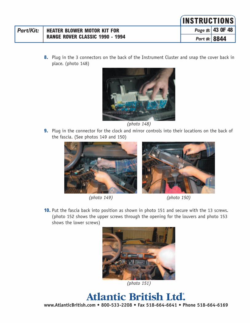
8. Plug in the 3 connectors on the back of the Instrument Cluster and snap the cover back in place. (photo 148)
9. Plug in the connector for the clock and mirror controls into their locations on the back of the fascia. (See photos 149 and 150)
10. Put the fascia back into position as shown in photo 151 and secure with the 13 screws. (photo 152 shows the upper screws through the opening for the louvers and photo 153 shows the lower screws)
Part/Kit: HEATER BLOWER MOTOR KIT FORRANGE ROVER CLASSIC 1990 - 1994
Page #: 43 OF 48
Part #: 8844
INSTRUCTIONS
www.AtlanticBritish.com • 800-533-2208 • Fax 518-664-6641 • Phone 518-664-6169Atlantic British Ltd. ®
(photo 148)
(photo 151)
(photo 149) (photo 150)
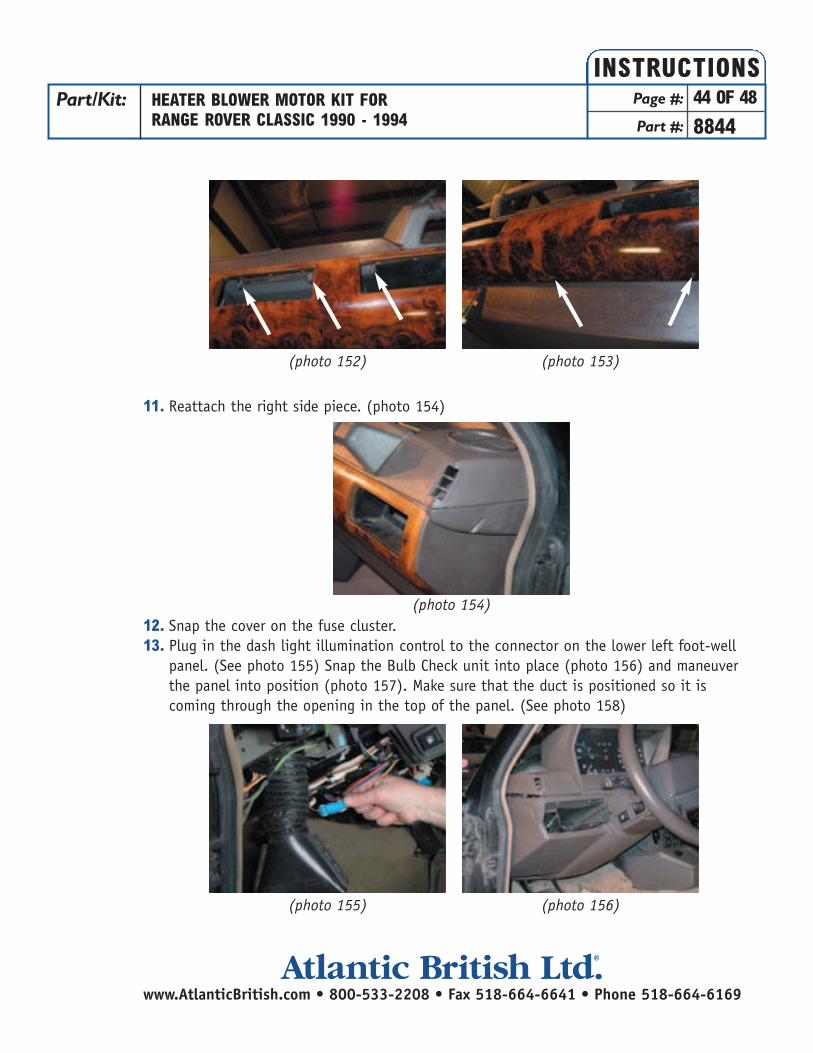
11. Reattach the right side piece. (photo 154)
12. Snap the cover on the fuse cluster.13. Plug in the dash light illumination control to the connector on the lower left foot-well
panel. (See photo 155) Snap the Bulb Check unit into place (photo 156) and maneuver the panel into position (photo 157). Make sure that the duct is positioned so it is coming through the opening in the top of the panel. (See photo 158)
Part/Kit: HEATER BLOWER MOTOR KIT FORRANGE ROVER CLASSIC 1990 - 1994
Page #: 44 OF 48
Part #: 8844
INSTRUCTIONS
www.AtlanticBritish.com • 800-533-2208 • Fax 518-664-6641 • Phone 518-664-6169Atlantic British Ltd. ®
(photo 152) (photo 153)
(photo 155) (photo 156)
(photo 154)

14. Secure the panel with the screws shown in photos 159, 160 and 161.
15. Position the short fascia piece to the left of the steering column (photo 162) and secure with the screws shown in photo 163. Replace the louver as shown in photo 164.
Part/Kit: HEATER BLOWER MOTOR KIT FORRANGE ROVER CLASSIC 1990 - 1994
Page #: 45 OF 48
Part #: 8844
INSTRUCTIONS
www.AtlanticBritish.com • 800-533-2208 • Fax 518-664-6641 • Phone 518-664-6169Atlantic British Ltd. ®
(photo 157) (photo 158)
(photo 160)
(photo 159) (photo 161)
(photo 163)(photo 162) (photo 164)
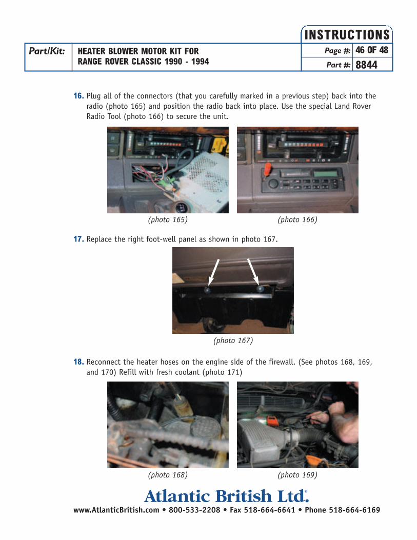
16. Plug all of the connectors (that you carefully marked in a previous step) back into the radio (photo 165) and position the radio back into place. Use the special Land Rover Radio Tool (photo 166) to secure the unit.
17. Replace the right foot-well panel as shown in photo 167.
18. Reconnect the heater hoses on the engine side of the firewall. (See photos 168, 169, and 170) Refill with fresh coolant (photo 171)
Part/Kit: HEATER BLOWER MOTOR KIT FORRANGE ROVER CLASSIC 1990 - 1994
Page #: 46 OF 48
Part #: 8844
INSTRUCTIONS
www.AtlanticBritish.com • 800-533-2208 • Fax 518-664-6641 • Phone 518-664-6169Atlantic British Ltd. ®
(photo 165)
(photo 167)
(photo 166)
(photo 168) (photo 169)

Replacing the Doors:
1. Reposition the door hinges over the 4 studs on the vehicle door frame. Secure with the snap ring on the upper and lower studs. (See photo 172)
Part/Kit: HEATER BLOWER MOTOR KIT FORRANGE ROVER CLASSIC 1990 - 1994
Page #: 47 OF 48
Part #: 8844
INSTRUCTIONS
www.AtlanticBritish.com • 800-533-2208 • Fax 518-664-6641 • Phone 518-664-6169Atlantic British Ltd. ®
(photo 170) (photo 171)
(photo 172)
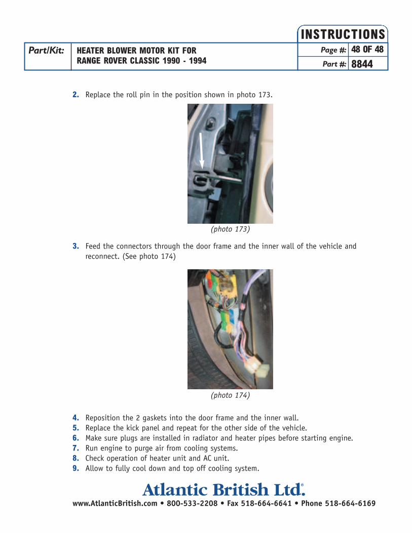
2. Replace the roll pin in the position shown in photo 173.
3. Feed the connectors through the door frame and the inner wall of the vehicle and reconnect. (See photo 174)
4. Reposition the 2 gaskets into the door frame and the inner wall.5. Replace the kick panel and repeat for the other side of the vehicle.6. Make sure plugs are installed in radiator and heater pipes before starting engine. 7. Run engine to purge air from cooling systems. 8. Check operation of heater unit and AC unit. 9. Allow to fully cool down and top off cooling system.
Part/Kit: HEATER BLOWER MOTOR KIT FORRANGE ROVER CLASSIC 1990 - 1994
Page #: 48 OF 48
Part #: 8844
INSTRUCTIONS
www.AtlanticBritish.com • 800-533-2208 • Fax 518-664-6641 • Phone 518-664-6169Atlantic British Ltd. ®
(photo 173)
(photo 174)