fastrax feb electric hot air blower owner's manual · i.1 fastrax® feb electric hot air...
TRANSCRIPT

Part No. M80000-004.Rev.1.01 Issued June 2017 Printed in Canada
Fastrax® FEBElectric Hot Air Blower
WARNING! Read all important information notices on page 3. Please adhere to instructions published in this manual. Failure to do so may be hazardous and may void certain provisions of your warranty.
Fastrax® is a registered trademark of CCI Thermal Technologies Inc. Copyright© 201. All rights reserved.
Owner's Manual For installation, maintenance, repair, and replacement parts.
FEB - 20 208 1 - L A 01
AC Voltage
208, 240,
480, 600
DC Voltage*600, 750
Phase
1
3
DCModel Series
FEB – Fastrax® Electric
Hot Air Blower
Model Coding
Kilowatts
20, 40, 60
Profile
Enclosure Material
Special
Construction
(if required)
A – Aluminum (Standard)
S – Stainless Steel
L – Standard
H – High

Table of Contents
A. Important Notices 3
B. Installation 4
B.1 Recommended Tools & Equipment ............................................................................... 4
B.2 Torque Specifications .................................................................................................... 4
B.3 Site Preparation ............................................................................................................ 4
B.4 Distribution Duct Assembly ........................................................................................... 5
B.5 Distribution Duct Installation .......................................................................................... 6
B.6 Distribution Duct Installation For Concrete Ties .............................................................. 7
B.7 Discharge Nozzle Installation ......................................................................................... 8
B.8 Electric Blower Installation ............................................................................................. 9
B.9 Flexible Duct Installation .............................................................................................. 10
B.10 Ground Snow Sensor Installation .............................................................................. 10
B.11 Electrical Termination ................................................................................................. 11
C. Wiring Schematics 12
C.1 Fastrax® FEB Electric Hot Air Blower - 20 kW Only, 240V, 1 Phase .............................. 12
C.2 Fastrax® FEB Electric Hot Air Blower - 20 kW, 40 kW & 60 kW, 480V, 3 Phase ........... 13
C.3 Fastrax® FEB Electric Hot Air Blower - 20 kW, 40 kW & 60 kW, 600V, 3 Phase ........... 14
D. Controls 15
D.1 Control Panel Features ................................................................................................ 15
D.2 Control System Operating Modes .............................................................................. 15
D.3 User Interface ............................................................................................................. 16
D.4 Remote Signalling ....................................................................................................... 17
D.5 Smart Relay Operation ................................................................................................ 17
D.6 Smart Relay Display .................................................................................................... 17
D.7 Smart Relay Operation ................................................................................................ 20
D.8 Protection ................................................................................................................... 23
D.9 Smart Relay Inputs and Outputs ................................................................................. 23
D.10 Control Panel Layout ................................................................................................. 24
E. Initial Startup/Commissioning 25
F. Quick Start Guide 25
G. Troubleshooting 26
H. Electric Blower Seasonal Maintenance 30
H.1 Fall Maintenance (Before Heating Season) ...............................................................................30
H.2 Spring Maintenance (After Heating Season) ..............................................................................31
I. Part Assembly Diagrams 32
I.1 Fastrax® FEB Electric Hot Air Blower Parts List - 20 kW ................................................ 32
I.2 Fastrax® FEB Electric Hot Air Blower Parts List - 40/60 kW ........................................... 33
I.3 Control Panel Parts List ................................................................................................ 34
I.4 Fastrax® FEDP Duct Package ...................................................................................... 35
J. Warranty 36

3
Important N
otices
Fastrax® is a leading manufacturer of complete engineered rail heating packages for freight railroads and transit. We provide the most efficient heat transfer products for rail track and switch equipment. These products are designed for low maintenance and long life for rugged use even in the harshest conditions. We also custom design and manufacture energy saving automated control packages to provide our customers with complete heating solutions for rail industry applications.
The Fastrax® FEB Electric Hot Air Blower switch heater prevents or removes ice and snow build up in the switch point area by delivering high velocity heated air to nozzles located at the switch point.
The Fastrax® FEB is assembled in a heavy-duty fully enclosed housing with easily accessible internal components. These components include a high velocity blower, rugged heating module and advanced electronic controls. The Fastrax® FEB comes standard with Fastrax® FEDP Duct Package and Fastrax® automatic aerial and ground snow sensing equipment.
A. IMPORTANT NOTICES
1. Read and follow all instructions in this manual.
2. Heater is to be connected and serviced only by a qualified electrician.
3. Installation and wiring of the heater must adhere to all applicable codes.
4. Disconnect heater from power supply at integral disconnect or fuse box before opening enclosures or servicing heater. IF INTEGRAL DISCONNECT IS BEING SERVICED, verify power has been disconnected at fuse box or main panel. Lock the switch in the “OFF” (open) position and tag the switch to prevent unexpected power application.
5. This heater is equipped with a bimetal over temperature high-limit. It is of the automatic reset type and therefore the heater may restart without warning. The heater is not to be operated with the high-limit disabled or disconnected from the control circuit.
6. Operate the heater only while it is permanently mounted in a horizontal position. Refer to Section B. Installation for details.
7. Follow the recommended maintenance procedures in Section H. Electric Blower Seasonal Maintenance.
8. Do not operate heater in ambient temperatures above 104°F (40°C).
9. Use factory approved replacement parts only.
10. See applicable electrical codes for seal requirements in field installed conduits. Factory installed conduits require no further sealing.
11. If there are any questions or concerns regarding the heater, contact the factory. Refer to the last page of this manual for details.
Read and adhere to the following. FAILURE TO DO SO MAY RESULT IN SEVERE OR FATAL INJURY. Warranty will be void.
WARNINGWARNING
CAUTIONThis symbol indicates a potentially hazardous situation, which, if not avoided, may result in personal injury or damage to the equipment.
CAUTION
This symbol indicates an imminently hazardous situation, which, if not avoided, can result in serious injury or damage to the equipment.
WARNING
WARNING

4
Inst
alla
tion
B. INSTALLATION
Read and adhere to the following installation instructions. FAILURE TO DO SO MAY RESULT IN SEVERE OR FATAL INJURY AND/OR POSSIBLE VOIDING OF THE WARRANTY.
WARNINGWARNING
B.1 Recommended Tools & Equipment
• Picker truck or other means of lifting and placing the electric blower unit (shipping weight with accessories is 585 lbs. (20 kW), 760 lbs. (40 kW), and 799 lbs. (60 kW).
• Electric impact wrench and sockets for running 9/16" lag bolts
• 3/8" electric drill for pilot holes
• Portable generator for electric power tools
• Basic combination wrench set and basic socket wrench set
• Inch pounds torque wrench
• Tape measure
• Pry bar for the removal of crating materials
• Reciprocating saw for removal of crating materials and trimming nozzles
• Shovel and rake for track ballast removal
• Lining and tamping bars
• Cold chisel and hammer
B.2 Torque Specifications
Electrical Equipment Torque Values
Part Type DescriptionTorque (in.lb.)
Terminals Control Circuits 9
Terminals Heater Load Circuits 27
Terminals Ground Block Terminals 14
Disconnect Up to 100A 50
Disconnect 100–200A 100
Contactors Pressure Plate Lugs 15–20
Contactors Box Lugs 40–45
Pwr. Dist. Block Primary 75
Pwr. Dist. Block Secondary 25–35
Circuit Breakers Heater and Control Loads 18
B.3 Site Preparation
1. The electric blower uses the FEDP Duct Package installed between two permanent load bearing ties.
2. Refer to the duct layout diagram on page 5.
3. Take care not to damage aerial snow sensor when removing the upper section of the shipping crate.
4. Remove the following and set aside for later assembly, (refer to diagram on page 5):
Duct Pieces - Distribution Duct Sections, Isolation blocks
Discharge Nozzles
Flexible Duct
Hardware Kit
Rail Affixing Straps
Ensure all equipment and components delivered match the shipping list provided. Notify CCI Thermal factory of any missing or damaged parts.
CAUTIONCAUTION
5. Carefully consider the placement of the distribution duct, bearing in mind the length and angle of the discharge nozzles and their proximity to the switch points.
5.1 Once the optimal position is identified, proceed with ballast removal allowing extra clearance for isolators and bolting flanges to pass underneath the rail. More information can be found in the Distribution Duct Installation section of this manual on page 6.
5.2 Nozzles can be trimmed if necessary. A reciprocating saw with a fine metal blade can be used for this operation. Maximum trim length is 3 inches.
6. Excavate the ballast from the predetermined area between two load bearing ties.
6.1 Allow a minimum of 10" of clearance below the rail for the entire width of the road bed.
Before testing tightness of any electrical connection, disconnect, tag and lockout electrical feeder to control panel to ensure entire panel is de-energized.
WARNINGWARNING
Aerial Snow Sensor

5
Installation
B.4 Distribution Duct Assembly
1. Assemble the distribution duct and electrical isolators as detailed in the drawing below.
Item
#Qty Description
Part Number
20 kW 40/60 kW
1 1 2 piece tie duct, 76" Fastrax® FEDP 12972 12984
2 1 Flex duct 60" - Fastrax® FEDP 12971-60 13031-60
3 24 Washer, 1/4 flat plated SAE 1516
4 24 Lockwasher 1/4" split 7406
5 24 Nut-1/4-20 UNC-H-SZP A10685-04
6 2 Isolation block c/w integrated bolts 12983 12986
2. Repeat the process for the attachment of the flexible duct and the distribution duct using the hardware and isolation block supplied as detailed in the drawing below.
P#7406x6
P#1516x12
P#4973x6
P#A10685-04x6
P#7406x12
P#1516x12
P#A10685-04x12
P#7406x12
P#1516x12
P#A10685-04x12
P#7406x6
P#1516x6
P#5113x6
P#12934x4
PER NOZZLE AND TIE STRAP
ITEM # PART # QTY DESCRIPTION
1 12972 1 2-PIECE TIE DUCT, 76" - FASTRAX EB
2 12973 2 POINT NOZZLE - FASTRAX EB
3 12971 1 FLEX DUCT 60" - FASTRAX EB
4 1516 48 WASHER, 1/4 FLAT PLATED SAE
5 7406 42 LOCKWASHER 1/4" SPLIT
6 A10685-04 30 Nut-1/4-20 UNC-H-SZP
7 4973 18 BOLT 1/4-20UNC x 3/4"LG, HEX HEAD
8 12934 8 LAG BOLT, 3/8" x 2"
9 12886 1 ELEMENT ENCL. c/w TIE DUCT BOLT PLATE - FASTRAX EB 20
10 12906 1 GASKET, TIE DUCT, GARLOCK 9850 - FASTRAX EB 20
11 12982 2 TIE STRAP - FASTRAX EB
12 12983 2 ISOLATION BLOCK c/w INTEGRATED BOLTSx1(NTS)
x1(NTS)
x1(NTS)
P#12983 / 12986
P#12983 / 12986
P#12906 / 13035
Do not exceed 50 in.lb. torque on the electrical isolation joints or the isolation block will be damaged.
WARNINGWARNING
NOTE: Ducting connections are electrically isolated to eliminate the possibility of short circuiting the rails. Connections are designed and tested to withstand 3000 volts for a duration of 1 minute.
Automatic Aerial Snow Sensor
Rail Affixing Straps
Isolation Blocks
Optional High Profile Air Intake
Optional Adjustable StandDischarge Nozzles
Structurally Reinforced Lifting Points
Automatic Ground Snow Sensor
Flexible Duct
Distribution Duct Sections
Main Electrical Wiring Entries
2
P#7406x6
P#1516x12
P#4973x6
P#A10685-04x6
P#7406x12
P#1516x12
P#A10685-04x12
P#7406x12
P#1516x12
P#A10685-04x12
P#7406x6
P#1516x6
P#5113x6
P#12934x4
PER NOZZLE AND TIE STRAP
ITEM # PART # QTY DESCRIPTION
1 12972 1 2-PIECE TIE DUCT, 76" - FASTRAX EB
2 12973 2 POINT NOZZLE - FASTRAX EB
3 12971 1 FLEX DUCT 60" - FASTRAX EB
4 1516 48 WASHER, 1/4 FLAT PLATED SAE
5 7406 42 LOCKWASHER 1/4" SPLIT
6 A10685-04 30 Nut-1/4-20 UNC-H-SZP
7 4973 18 BOLT 1/4-20UNC x 3/4"LG, HEX HEAD
8 12934 8 LAG BOLT, 3/8" x 2"
9 12886 1 ELEMENT ENCL. c/w TIE DUCT BOLT PLATE - FASTRAX EB 20
10 12906 1 GASKET, TIE DUCT, GARLOCK 9850 - FASTRAX EB 20
11 12982 2 TIE STRAP - FASTRAX EB
12 12983 2 ISOLATION BLOCK c/w INTEGRATED BOLTSx1(NTS)
x1(NTS)
x1(NTS)
P#12983 / 12986
P#12983 / 12986
P#12906 / 13035
1
43
5
6
45 3
1
43
5 6
4
5
3
P#7406x6
P#1516x12
P#4973x6
P#A10685-04x6
P#7406x12
P#1516x12
P#A10685-04x12
P#7406x12
P#1516x12
P#A10685-04x12
P#7406x6
P#1516x6
P#5113x6
P#12934x4
PER NOZZLE AND TIE STRAP
ITEM # PART # QTY DESCRIPTION
1 12972 1 2-PIECE TIE DUCT, 76" - FASTRAX EB
2 12973 2 POINT NOZZLE - FASTRAX EB
3 12971 1 FLEX DUCT 60" - FASTRAX EB
4 1516 48 WASHER, 1/4 FLAT PLATED SAE
5 7406 42 LOCKWASHER 1/4" SPLIT
6 A10685-04 30 Nut-1/4-20 UNC-H-SZP
7 4973 18 BOLT 1/4-20UNC x 3/4"LG, HEX HEAD
8 12934 8 LAG BOLT, 3/8" x 2"
9 12886 1 ELEMENT ENCL. c/w TIE DUCT BOLT PLATE - FASTRAX EB 20
10 12906 1 GASKET, TIE DUCT, GARLOCK 9850 - FASTRAX EB 20
11 12982 2 TIE STRAP - FASTRAX EB
12 12983 2 ISOLATION BLOCK c/w INTEGRATED BOLTSx1(NTS)
x1(NTS)
x1(NTS)
P#12983 / 12986
P#12983 / 12986
P#12906 / 13035
P#7406x6
P#1516x12
P#4973x6
P#A10685-04x6
P#7406x12
P#1516x12
P#A10685-04x12
P#7406x12
P#1516x12
P#A10685-04x12
P#7406x6
P#1516x6
P#5113x6
P#12934x4
PER NOZZLE AND TIE STRAP
ITEM # PART # QTY DESCRIPTION
1 12972 1 2-PIECE TIE DUCT, 76" - FASTRAX EB
2 12973 2 POINT NOZZLE - FASTRAX EB
3 12971 1 FLEX DUCT 60" - FASTRAX EB
4 1516 48 WASHER, 1/4 FLAT PLATED SAE
5 7406 42 LOCKWASHER 1/4" SPLIT
6 A10685-04 30 Nut-1/4-20 UNC-H-SZP
7 4973 18 BOLT 1/4-20UNC x 3/4"LG, HEX HEAD
8 12934 8 LAG BOLT, 3/8" x 2"
9 12886 1 ELEMENT ENCL. c/w TIE DUCT BOLT PLATE - FASTRAX EB 20
10 12906 1 GASKET, TIE DUCT, GARLOCK 9850 - FASTRAX EB 20
11 12982 2 TIE STRAP - FASTRAX EB
12 12983 2 ISOLATION BLOCK c/w INTEGRATED BOLTSx1(NTS)
x1(NTS)
x1(NTS)
P#12983 / 12986
P#12983 / 12986
P#12906 / 13035
Main Tie Duct

6
Inst
alla
tion
B.5 Distribution Duct Installation
1. Position the assembled distribution duct in the excavated area between the ties by placing the closed end under the rail.
2. Slide the assembled distribution duct in the excavated area until the nozzle discharge openings are at equal distances between the rails.
3. Use temporary blocking to raise the distribution duct until it is flush with the undersides of both rails.
4. Temporarily insert the discharge nozzles into their sockets in the distribution duct and verify that the nozzle tips will not interfere with the switch points. Leave a minimum of 2" clearance between the end of the nozzle and the rail web.
5. Adjust the distribution duct position as necessary before installing the tie straps as shown in the photo below. For ease of installation, pre-drill pilot holes to facilitate threading of the lag bolts into the railroad tie.
6. Carefully replace the ballast underneath and along each side of the distribution duct. Ensure the duct remains level and the discharge nozzles are aimed at the rail web of the switch point, not above or below. Ensure the nozzle is positioned correctly to remove snow between the switch points.
7. Remove the blocking and back fill with ballast as required.

7
Installation
B.6 Distribution Duct Installation For Concrete Ties
1. Position the assembled distribution duct in the excavated area between the ties by placing the closed end under the rail.
2. Temporarily block up ducting to a height where tie straps can be attached. Attach the Tie Straps and remove blocking. Ducting should hang from the ties by the tie straps.
3. Turn each jack bolt out until the points are secure against concrete wall of ties. Tighten with wrench until tool tight.
4. Turn keeper nut down to secure each jack bolt into place. Duct should now be secure at the height desired.
5. Remove the tie straps and apply epoxy to both ends where it will contact the ties.
6. Carefully place the tie straps back onto ties by aligning bolting holes and securing with provided hardware.
7. Back fill with ballast as required.

8
Inst
alla
tion
B.7 Discharge Nozzle Installation
1. Complete the installation of the nozzles using the hardware as detailed in the drawing below. Follow the precise installation order to ensure proper assembly.
Item
#Qty Description
Part Number
20 kW 40/60 kW
1 2 Discharge nozzle - Fastrax® FEDP 12973 12985
2 12 Washer, 1/4 flat plated SAE 1516
3 12 Lockwasher 1/4" split 7406
4 12 Bolt 1/4-20UNC x 1" LG, Hex Head 5113
5 8 Lag bolt, 3/8" x 2" 12934
6 2 Tie strap - Fastrax® FEB 12982
2. Insert the discharge nozzles into their sockets. Aim the nozzles at the rail web of the switch points and secure in position.
2.1 Using a multimeter, verify the distribution duct sections are electrically isolated from one another by checking for lack of continuity.
P#7406x6
P#1516x12
P#4973x6
P#A10685-04x6
P#7406x12
P#1516x12
P#A10685-04x12
P#7406x12
P#1516x12
P#A10685-04x12
P#7406x6
P#1516x6
P#5113x6
P#12934x4
PER NOZZLE AND TIE STRAP
ITEM # PART # QTY DESCRIPTION
1 12972 1 2-PIECE TIE DUCT, 76" - FASTRAX EB
2 12973 2 POINT NOZZLE - FASTRAX EB
3 12971 1 FLEX DUCT 60" - FASTRAX EB
4 1516 48 WASHER, 1/4 FLAT PLATED SAE
5 7406 42 LOCKWASHER 1/4" SPLIT
6 A10685-04 30 Nut-1/4-20 UNC-H-SZP
7 4973 18 BOLT 1/4-20UNC x 3/4"LG, HEX HEAD
8 12934 8 LAG BOLT, 3/8" x 2"
9 12886 1 ELEMENT ENCL. c/w TIE DUCT BOLT PLATE - FASTRAX EB 20
10 12906 1 GASKET, TIE DUCT, GARLOCK 9850 - FASTRAX EB 20
11 12982 2 TIE STRAP - FASTRAX EB
12 12983 2 ISOLATION BLOCK c/w INTEGRATED BOLTSx1(NTS)
x1(NTS)
x1(NTS)
P#12983 / 12986
P#12983 / 12986
P#12906 / 13035
1
4
4
3
2
52
3
6

9
Installation
B.8 Electric Blower Installation
1. Prepare the area where the electric blower unit will be placed.
1.1 The area should be clear of any foliage or foreign objects that might be drawn into the Fastrax® FEB ‘s air intake.
2. Ensure the grade is level before installation. A thick layer of ballast material providing good drainage is recommended.
3. The electric blower unit is shipped on pressure treated wooden blocks which should be left in place to ensure maximum protection from water ingress; an optional adjustable metal stand is available.
Wood Stand
4. Using the four lifting points, lift the unit and place it perpendicular or parallel to the track bed.
4.1 Ensure it is close enough for the flexible duct to reach between the connecting flanges on the blower discharge and the distribution duct inlet without obstruction or pinching.
5. Once the electric blower unit is in position remove the remaining exterior crating except for the wooden base blocks attached to the unit.
5.1 Ensure no projections on the unit interfere with the rail line foul zone.
Adjustable Stand
Ensure the unit is installed at least six inches above the level at which ground water might accumulate. Failure to do so could cause damage to the unit and void the warranty.
WARNING
WARNING
6"
At least six inches above grade

10
Inst
alla
tion
B.9 Flexible Duct Installation
Item
#Qty Description
Part Number
20 kW 40/60 kW
1 1 Flex duct 60" - Fastrax® FEDP 12971-60 13031-60
2 12 Washer, 1/4 flat plated SAE 1516
3 6 Lockwasher 1/4" split 7406
4 6 Nut-1/4-20 UNC-H-SZP A10685-04
5 2Bolt 1/4-20UNC x 3/4" LG,
Hex Head4973
6 1Element Encl. c/w tie duct bolt
plate - Fastrax®12886
7 1Gasket, tie duct, garlock
9850 - Fastrax®12906 13035
8 4 Bolt 1/4-20UNC x 1" LG, Hex Head 5113 13033
1. Attach the flexible duct to the blower discharge flange with the gasket and hardware provided as shown in diagram above.
2. Draw the fasteners snug in an even diagonal pattern and torque to 50 in.lb.
3. To eliminate excess strain on the duct and connections, ballast may be used to support the flexible duct as required.
3.1 Additional ballast can be added around the perimeter of the blower unit and between the blocking to keep the unit firmly in place.
4. Using a multimeter, verify the flexible duct and distribution duct sections are electrically isolated from one another by checking to ensure there is no continuity.
B.10 Ground Snow Sensor Installation
1. Select an elevated location for the ground snow sensor. Bolting the ground snow sensor to the end of the rail tie, where possible, is recommended.
1.1 Secure in place, as depicted in the pictures below.
P#7406x6
P#1516x12
P#4973x2
P#A10685-04x6
P#7406x12
P#1516x12
P#A10685-04x12
P#7406x12
P#1516x12
P#A10685-04x12
P#7406x6
P#1516x6
P#5113x6
P#12934x4
PER NOZZLE AND TIE STRAP
ITEM # PART # QTY DESCRIPTION
1 12972 1 2-PIECE TIE DUCT, 76" - FASTRAX EB
2 12973 2 DISCHARGE NOZZLE - FASTRAX® FEDP
3 12971 1 FLEX DUCT 60" - FASTRAX EB
4 1516 48 WASHER, 1/4 FLAT PLATED SAE
5 7406 42 LOCKWASHER 1/4" SPLIT
6 A10685-04 30 Nut-1/4-20 UNC-H-SZP
7 4973 2 BOLT 1/4-20UNC x 3/4"LG, HEX HEAD
8 12934 8 LAG BOLT, 3/8" x 2"
9 12886 1 ELEMENT ENCL. c/w TIE DUCT BOLTPLATE - FEB 20
10 12906 1 GASKET, TIE DUCT - FEB 20
11 5113 16 BOLT 1/4-20UNC x 1"LG, HEX HEAD
12 12982 2 TIE STRAP - FASTRAX EB
13 12983 2 ISOLATION BLOCK c/w INTEGRATEDBOLTS
1
2
3 5 4
4 5 6
4 5 6
6 5 4
P#12983x1
(NTS)
P#12983x1
(NTS)
11
5
4
11
5
4
8
13
13
12
P#12906x1
(NTS)6
1
N/AHARDWARE, DUCTING PACKAGE
ANGULAR
CHK'D BY:
APP'D. BY:
SCALE:
DRN BY:
±DWG NO.:
TITLE:
SYTELINE NO.: METRIC
TOLERANCE UNLESS NOTED OTHERWISE
DECIMAL FRACTIONAL
REVISION DESCRIPTIONREV. BYDATE
1/2° 0.005" 1/16" 1 mmSHEET:
GMillard 19 Feb 2016
± ± ±
EDMONTON, ALBERTA
1 OF 3
P#5113x2
6
7
1
25
2
4
3
P#7406x6
P#1516x12
P#4973x6
P#A10685-04x6
P#7406x12
P#1516x12
P#A10685-04x12
P#7406x12
P#1516x12
P#A10685-04x12
P#7406x6
P#1516x6
P#5113x6
P#12934x4
PER NOZZLE AND TIE STRAP
ITEM # PART # QTY DESCRIPTION
1 12972 1 2-PIECE TIE DUCT, 76" - FASTRAX EB
2 12973 2 POINT NOZZLE - FASTRAX EB
3 12971 1 FLEX DUCT 60" - FASTRAX EB
4 1516 48 WASHER, 1/4 FLAT PLATED SAE
5 7406 42 LOCKWASHER 1/4" SPLIT
6 A10685-04 30 Nut-1/4-20 UNC-H-SZP
7 4973 18 BOLT 1/4-20UNC x 3/4"LG, HEX HEAD
8 12934 8 LAG BOLT, 3/8" x 2"
9 12886 1 ELEMENT ENCL. c/w TIE DUCT BOLT PLATE - FASTRAX EB 20
10 12906 1 GASKET, TIE DUCT, GARLOCK 9850 - FASTRAX EB 20
11 12982 2 TIE STRAP - FASTRAX EB
12 12983 2 ISOLATION BLOCK c/w INTEGRATED BOLTSx1(NTS)
x1(NTS)
x1(NTS)
P#12983 / 12986
P#12983 / 12986
P#12906 / 13035
8

11
Installation
B.11 Electrical Termination
Surge Protection Recommendations
This electric blower utilizes a number of processor-based control systems, all of which are susceptible to damage from lightning and other electrical surges. While every effort has been made to ensure that the control systems have been adequately ‘hardened’, CCI Thermal’s surge mitigation efforts can only be effective if ALL external remote circuits connecting to the electric blower have been protected by primary surge protection devices in accordance with the following generally accepted requirements for surge protection of wayside signal equipment:
• Provide primary surge protection devices (standard signal air gap arresters) on all external electric blower control I/O circuits. These arresters should be located
“upstream” of the electric blower housing (within the signal housing, which interfaces to the electric blower). It is essential to protect ALL circuits entering or leaving the signal housing.
• Provide a primary surge protection device (commercial high capacity MOV type) on the external electric blower AC power feed. This surge protection device should be located “upstream” of the electric blower in conjunction with the electrical service entrance panel and main disconnect. Observe primary surge protector manufacturer’s instructions for installation and circuit breaker protection (if required).
• Grounding of the electric blower metal housing as well as the ground terminals of the primary arresters is essential for personnel protection as well as surge protection. Grounding rods and conductors must be installed in accordance with the AREMA Signal Manual of Recommended Practice.
• Primary surge protection must be installed in accordance with the AREMA Signal Manual of Recommended Practice.
Electrical connections are to be performed by qualified personnel and in accordance with the local electrical code and the local electrical authority.
WARNINGWARNING
1. Connection entries for electrical conduits are located on the right hand side of the discharge duct. The power connection entry is 1 1/4" NPT and the remote signal entry is 1/2" NPT.
2. The use of water tight connections for incoming conduits is mandatory. See applicable electrical codes for seal requirements of field installed conduits.
3. Conductors are to be sized in accordance with the electrical code and the minimum circuit ampacity data as detailed on the unit’s data plate.
4. Incoming supply lines should be connected directly to the main disconnect switch. Where applicable the neutral should be connected to the neutral lug and grounded at the source.
See photo detail below for electrical connection points.Electrical Connection Points
5. The control chassis and the rest of the main unit must be connected to ground.
6. The maximum allowable deviation from rated voltage to supply line voltage is 5%. Verify voltage is present on all three lines for three phase units and two lines for single phase units.
7. Customer requested external low voltage signal inputs and outputs shall be routed through the secondary connection point adjacent to the main power connection. Termination of remote operator controls is found in Section D. Controls of this manual under D.4 Remote Signalling.
8. Manually spin the blower shaft to ensure the blower turns freely.
9. The electric blower unit is electrically isolated from the track by the isolation block between the distribution duct and the flexible duct.

12
Wiri
ng S
chem
atic
s
C. WIRING SCHEMATICS
C.1 Fastrax® FEB Electric Hot Air Blower - 20 kW Only, 240V, 1 Phase
Smar
tRe
lay
EATO
NEa
sy71
9-AB
-RC
Cont
rol T
rans
form
er 2
50 V
A
L
Out
put 1
Q1-
2
Out
put 1
Q1-
1
Out
put 2
Q2-
2
Out
put 2
Q2-
1
Out
put 4
Q4-
2
Out
put 4
Q4-
1
Blow
er O
n
G
Cont
rol O
n
W
Elem
enta
ry W
iring
Dia
gram
Fiel
d W
iring
Aeria
lSn
owSe
nsor Sn
owSe
nsed
L2L1
Rem
ote
Sign
als
G
Heat
On
Out
put 3
Q3-
2
Out
put 3
Q3-
1
High
Tem
pera
ture
Lim
it
230V
N
C1
Blow
erCo
ntac
tor
C2
Heat
erCo
ntac
tor
Disc
onne
ct S
witc
h60
0 V,
200
A24
0 V,
75
HP
CB24
0-2
Prim
ary
Cont
rol
Circ
uit B
reak
er48
0Y/2
77V,
2 A
MS2
40-1
/Au
x
CR1
Faul
t Fee
dbac
kRe
lay
R
C1/A
ux/A
Run
Feed
back
120
VAC
10 A
C
NCNO
CR1/
BFa
ult F
eedb
ack
120
VAC
10 A
C
NCNO
AS24
-1
AS24
-2
SSA-
1
SSA-
2
A1 A2 A3 A4 A5 A6RSS-
2
RSS-
1
Pow
er
L1 L2
Grou
ndSn
owSe
nsor Sn
owSe
nsed
L2L1GS
24-1
GS24
-2
SSG-
1
SSG-
2
CR2/
ACR
3/A
Syst
em F
ault
R
CR1/
A
C
NCNO
Man
ual S
tart
RSS-
1RS
S-2
Man
ual S
top
Cold
Air
Mod
e
CR3/
B
MS2
40-1
/Aux
CB24
-3/
Aux
CB24
-2/
Aux
Rem
ote
Tim
eout
Mod
e
Blow
er M
otor
3 HP
, 345
0 RP
M,
1Φ, 6
0 Hz
,23
0 V,
14.
5 FL
A
M
Lege
nd:
Pane
l Wiri
ng
Fiel
d W
iring
Term
inal
Blo
ck
C2He
ater
Con
tact
or60
0 V,
105
A
Duct
Hea
ter
20 k
W, 2
40 V
, 1Φ
CB24
0-1
Heat
er B
ranc
hCi
rcui
t Bre
aker
480Y
/277
V, 1
25 A
Rem
ote
Star
t/St
op12
0 VA
C
Rem
ote
Star
t:RS
S-1
and
RSS-
2 cl
osed
Run
Indi
catio
n:A1
and
A2
clos
edA1
and
A3
open
ed
Faul
t Ind
icat
ion:
A4 a
nd A
6 cl
osed
A4 a
nd A
5 op
ened
TSA-
1TS
A-2
CR2
TSB-
2TS
B-2
CR3
MS2
40-1
Com
bina
tion
Mot
or C
ontr
olle
r23
0 V,
5 H
PSe
ttin
g: 1
5 A
C1Bl
ower
Con
tact
or23
0 V,
7.5
HP
CR2/
B
Prim
ary
High
Tem
pera
ture
Lim
it30
0 °F
Set
poin
t, Au
to R
eset
Back
up H
igh
Tem
pera
ture
Lim
it40
0 °F
Set
poin
t, M
anua
l Res
et
24V
CB24
-1Se
cond
ary
Cont
rol
Circ
uit B
reak
er27
7 V,
3 A
CB24
-2Ae
rial S
now
Sen
sor
Circ
uit B
reak
er27
7 V,
2 A
CB24
-3Gr
ound
Sno
w S
enso
rCi
rcui
t Bre
aker
277
V, 4
A
Inpu
t 2I2 In
put 3
I3Inpu
t 1I1 In
put 4
I4 Inpu
t 5I5 In
put 6
I6 Inpu
t 7I7 In
put 8
I8 Inpu
t 9I9 In
put 1
1I1
1
Inpu
t 10
I10
SSG-
1SS
G-2
SSA-
1SS
A-2
C1/
Aux/
B

13
Wiring S
chematics
Smar
tRe
lay
EATO
NEa
sy71
9-AB
-RC
L
Out
put 1
Q1-
2
Out
put 1
Q1-
1
Out
put 2
Q2-
2
Out
put 2
Q2-
1
Out
put 4
Q4-
2
Out
put 4
Q4-
1
Blow
er O
n
G
Cont
rol O
n
W
Fiel
d W
iring
Aeria
lSn
owSe
nsor Sn
owSe
nsed
L2L1
Rem
ote
Sign
als
G
Heat
On
Out
put 3
Q3-
2
Out
put 3
Q3-
1
High
Tem
pera
ture
Lim
it
N
C1
Blow
erCo
ntac
tor
C2
Heat
erCo
ntac
tor
Disc
onne
ct S
witc
h60
0 V,
40
A (4
0 kW
Mod
els:
80
A, 6
0 kW
Mod
els:
100
A)
480
V, 2
0 HP
(40
kW M
odel
s: 4
0 HP
, 60
kW M
odel
s: 5
0 HP
)
MS4
80-1
/Au
x
CR1
Faul
t Fee
dbac
kRe
lay
R
C1/A
ux/A
Run
Feed
back
120
VAC
10 A
C
NCNO
CR1/
BFa
ult F
eedb
ack
120
VAC
10 A
C
NCNO
AS24
-1
AS24
-2
SSA-
1
SSA-
2
A1 A2 A3 A4 A5 A6RSS-
2
RSS-
1
Pow
er
L1 L2 L3
Grou
ndSn
owSe
nsor Sn
owSe
nsed
L2L1GS
24-1
GS24
-2
SSG-
1
SSG-
2
CR2/
ACR
3/A
Syst
em F
ault
R
CR1/
A
C
NCNO
Inpu
t 2I2
Man
ual S
tart
Inpu
t 3I3
RSS-
1RS
S-2
Inpu
t 1I1
Man
ual S
top
Inpu
t 4I4
Cold
Air
Mod
e
Inpu
t 5I5 In
put 6
I6
CR3/
B
Inpu
t 7I7
MS4
80-1
/Aux
Inpu
t 8I8 In
put 9
I9
CB24
-3/
Aux
CB24
-2/
Aux
Rem
ote
Tim
eout
Mod
eIn
put 1
1I1
1
Lege
nd:
Pane
l Wiri
ng
Fiel
d W
iring
Term
inal
Blo
ck
Rem
ote
Star
t/St
op12
0 VA
C
Rem
ote
Star
t:RS
S-1
and
RSS-
2 cl
osed
Run
Indi
catio
n:A1
and
A2
clos
edA1
and
A3
open
ed
Faul
t Ind
icat
ion:
A4 a
nd A
6 cl
osed
A4 a
nd A
5 op
ened
CB24
-2Ae
rial S
now
Sen
sor
Circ
uit B
reak
er27
7 V,
2 A
CB24
-3Gr
ound
Sno
w S
enso
rCi
rcui
t Bre
aker
277
V, 4
A
CR2/
B
SSG-
1SS
G-2
SSA-
1SS
A-2
Inpu
t 10
I10
Cont
rol T
rans
form
er 2
50 V
A
460V
CB48
0-2
Prim
ary
Cont
rol
Circ
uit B
reak
er48
0Y/2
77V,
1 A
24V
CB24
-1Se
cond
ary
Cont
rol
Circ
uit B
reak
er27
7 V,
3 A
C1/
Aux/
B
TSA-
1TS
A-2
CR2
TSB-
2TS
B-2
CR3
Prim
ary
High
Tem
pera
ture
Lim
it30
0 °F
Set
poin
t, Au
to R
eset
Back
up H
igh
Tem
pera
ture
Lim
it40
0 °F
Set
poin
t, M
anua
l Res
et
Inpu
t 12
I12
Cont
rol A
mbi
ent
High
Tem
pera
ture
Lim
it
40 k
W a
nd 6
0 kW
Mod
els O
nly
Blow
er M
otor
460
V, 3
500
RPM
,3Φ
, 60
Hz,
3 HP
, 3.4
FLA
(7.5
HP,
9 F
LA in
40 &
60
kW M
odel
s)
M
C2He
ater
Con
tact
or48
0 V,
45
A(5
5 A
in 4
0 kW
Mod
el)
(105
A in
60
kW M
odel
)
Duct
Hea
ter 1
20 k
W, 4
80 V
, 3Φ
CB48
0-1
Heat
er B
ranc
hCi
rcui
t Bre
aker
480V
, 25
A(6
0 A
in 4
0 kW
Mod
el)
(90
A in
60
kW M
odel
)
C1Bl
ower
Con
tact
or46
0 V,
15
HP
Duct
Hea
ter 2
20 k
W, 4
80 V
, 3Φ
Duct
Hea
ter 3
20 k
W, 4
80 V
, 3Φ
40 k
W a
nd 6
0 kW
Mod
els O
nly
60 k
W M
odel
s Onl
y
MS4
80-1
Com
bina
tion
Mot
or C
ontr
olle
r46
0 V,
3 H
P, S
ettin
g: 4
A(4
60 V
, 7.5
HP,
Set
ting:
11
Ain
40
& 6
0 kW
Mod
els)
C.2 Fastrax® FEB Electric Hot Air Blower - 20 kW, 40 kW & 60 kW, 480V, 3 Phase

14
Wiri
ng S
chem
atic
s
C.3 Fastrax® FEB Electric Hot Air Blower - 20 kW, 40 kW & 60 kW, 600V, 3 Phase
Smar
tRe
lay
EATO
NEa
sy71
9-AB
-RC
Cont
rol T
rans
form
er 2
50 V
A
L
Out
put 1
Q1-
2
Out
put 1
Q1-
1
Out
put 2
Q2-
2
Out
put 2
Q2-
1
Out
put 4
Q4-
2
Out
put 4
Q4-
1
Blow
er O
n
G
Cont
rol O
n
W
Fiel
d W
iring
Aeria
lSn
owSe
nsor Sn
owSe
nsed
L2L1
Rem
ote
Sign
als
G
Heat
On
Out
put 3
Q3-
2
Out
put 3
Q3-
1
High
Tem
pera
ture
Lim
it
575V
N
C1
Blow
erCo
ntac
tor
C2
Heat
erCo
ntac
tor
MS6
00-1
/Au
x
CR1
Faul
t Fee
dbac
kRe
lay
R
C1/A
ux/A
Run
Feed
back
120
VAC
10 A
C
NCNO
CR1/
BFa
ult F
eedb
ack
120
VAC
10 A
C
NCNO
AS24
-1
AS24
-2
SSA-
1
SSA-
2
A1 A2 A3 A4 A5 A6RSS-
2
RSS-
1
Pow
er
L1 L2 L3
Grou
ndSn
owSe
nsor Sn
owSe
nsed
L2L1GS
24-1
GS24
-2
SSG-
1
SSG-
2
CR2/
ACR
3/A
Syst
em F
ault
R
CR1/
A
C
NCNO
Man
ual S
tart
RSS-
1RS
S-2
Man
ual S
top
Cold
Air
Mod
e
CR3/
B
MS6
00-1
/Aux
CB24
-3/
Aux
CB24
-2/
Aux
Rem
ote
Tim
eout
Mod
e
Blow
er M
otor
575
V, 3
500
RPM
,3Φ
, 60
Hz,
3 HP
, 2.7
FLA
(7.5
HP,
7.4
FLA
in40
& 6
0 kW
Mod
els)
M
Lege
nd:
Pane
l Wiri
ng
Fiel
d W
iring
Term
inal
Blo
ck
C2He
ater
Con
tact
or60
0 V,
45
A(5
5 A
in 4
0 kW
Mod
el)
(105
A in
60
kW M
odel
)
Duct
Hea
ter 1
20 k
W, 6
00 V
, 3Φ
CB60
0-1
Heat
er B
ranc
hCi
rcui
t Bre
aker
600V
, 25
A(5
0 A
in 4
0 kW
Mod
el)
(80
A in
60
kW M
odel
)
Rem
ote
Star
t/St
op12
0 VA
C
Rem
ote
Star
t:RS
S-1
and
RSS-
2 cl
osed
Run
Indi
catio
n:A1
and
A2
clos
edA1
and
A3
open
ed
Faul
t Ind
icat
ion:
A4 a
nd A
6 cl
osed
A4 a
nd A
5 op
ened
TSA-
1TS
A-2
CR2
TSB-
2TS
B-2
CR3
C1Bl
ower
Con
tact
or57
5 V,
20
HP
Duct
Hea
ter 2
20 k
W, 6
00 V
, 3Φ
Duct
Hea
ter 3
20 k
W, 6
00 V
, 3Φ
CR2/
B
40 k
W a
nd 6
0 kW
Mod
els O
nly
60 k
W M
odel
s Onl
y
Prim
ary
High
Tem
pera
ture
Lim
it30
0 °F
Set
poin
t, Au
to R
eset
Back
up H
igh
Tem
pera
ture
Lim
it40
0 °F
Set
poin
t, M
anua
l Res
et
MS6
00-1
Com
bina
tion
Mot
or C
ontr
olle
r57
5 V,
3 H
P, S
ettin
g: 3
A(5
75 V
, 7.5
HP,
Set
ting:
9 A
in 4
0 &
60
kW M
odel
s)
SSG-
1SS
G-2
SSA-
1SS
A-2
Inpu
t 2I2 In
put 3
I3Inpu
t 1I1 In
put 4
I4 Inpu
t 5I5 In
put 6
I6 Inpu
t 7I7 In
put 8
I8 Inpu
t 9I9 In
put 1
1I1
1
Inpu
t 10
I10
24V
CB24
-1Se
cond
ary
Cont
rol
Circ
uit B
reak
er27
7 V,
3 A
CB24
-2Ae
rial S
now
Sen
sor
Circ
uit B
reak
er27
7 V,
2 A
CB24
-3Gr
ound
Sno
w S
enso
rCi
rcui
t Bre
aker
277
V, 4
A
MS6
00-2
Tran
sfor
mer
Circ
uit B
reak
er60
0 V,
1.6
A, S
ettin
g: 1
.4 A
Disc
onne
ct S
witc
h60
0 V,
40
A (4
0 kW
Mod
els:
60
A, 6
0 kW
Mod
els:
80
A)60
0 V,
25
HP (4
0 kW
Mod
els:
30
HP, 6
0 kW
Mod
els:
40
HP)
C1/
Aux/
B
Inpu
t 12
I12
Cont
rol A
mbi
ent
High
Tem
pera
ture
Lim
it
40 k
W a
nd 6
0 kW
Mod
els O
nly

15
Controls
D. CONTROLS
The Fastrax® FEB electric blower control panel located inside the unit incorporates modern technology including a smart relay to ensure efficient and economical operation and is designed for ease of operation and servicing. Each control panel is NEMA 4 rated for protection against moisture.
The controls have been preconfigured for optimal snow melting operation with minimum user input. If desired, advanced diagnostics, troubleshooting and timing/mode adjustment features are readily available.
D.1 Control Panel Features
Control System Features
• Automatic snow clearing operation driven by ground and aerial snow sensors
• Local manual start/stop• Remote start/stop• User adjustable preset run time (1 minute to 100 hours)• Counts and displays total number of operating hours in
service
• Selectable modes
• Hot/cold air and Remote timeout on/offUser Friendly Interface Features
• User friendly door mounted operators and LED indicators• Local run status and fault indication• Remote run and fault indication • Advanced diagnostics and troubleshooting displays
including fault history
Equipment Protection Features
• Overheat protection system including: • Automatic fan shutdown delay • High temperature limiting devices including
separate primary automatically reset and backup manually reset bimetal disc thermostats
• Motor protection including class 10 overload relay
• Coordinated overcurrent protection of all electrical components by resettable circuit breakers and motor controllers
• User adjustable remote start delay prevents simultaneous inrush of multiple units
• Staggered starting of motor and elements to minimize peak current draw
• Self monitoring and automatic adjustment to minimize risk of damage while maintaining a reduced but effective level of snow clearing and sensing operation in the event of some installation issues or equipment failures
D.2 Control System Operating Modes
1. Timed Local Run Mode: The Fastrax® FEB enters this mode if the “MANUAL START” button is pushed for 3 seconds or one of the snow sensors detects snow. The Fastrax® FEB will run in this mode until the red “MANUAL START” button is released and the snow sensors no longer detect snow, at which point it will begin a timed run where it will continue to run in this mode until the preset run time (2 hours by default) has elapsed. The run timer will be reset if the “MANUAL START” button is pushed or one of the snow sensors detects snow again.
2. Timed Remote Run Mode: The Fastrax® FEB enters this mode after the remote start/stop contacts are held closed while
“REMOTE TIMEOUT MODE” is on (default). The Fastrax® FEB will begin a timed run and will continue to run until the preset run time has elapsed or the remote start/stop contacts are opened.
NOTE: Opening of the remote start/stop contacts will cancel the timed run if the snow sensors are not currently detecting snow.
3. Continuous Remote Run Mode: The Fastrax® FEB is in this mode while the remote start/stop contacts are closed and
“REMOTE TIMEOUT MODE” is off. The Fastrax® FEB will run in “CONTINUOUS REMOTE RUN MODE” until the remote start/stop contacts are opened.
4. Cooldown Mode: If “COLD AIR MODE” is off, the Fastrax® FEB enters “COOLDOWN MODE” after exiting the run modes. The Fastrax® FEB will run in “COOLDOWN MODE” where the duct heater is off and the blower continues to run until the preset cooldown time (3 minutes) has elapsed or the Fastrax® FEB is forced to re-enter a run mode.
5. Cold Air Mode: This mode increases energy efficiency in exchange for reduced snow clearing capability. While
“COLD AIR MODE” is inactive (default), the Fastrax® FEB discharges heated air while it is running. While “COLD AIR MODE” is active, the Fastrax® FEB discharges cold air while it is running. The Fastrax® FEB may be forced to enter this mode regardless of the setting of the “COLD AIR MODE” selector switch if the primary high temperature limit trips repetitively due to a serious issue with equipment or installation. In this case, the Fastrax® FEB will remain in cold air mode until the issue has been resolved and the unit has been manually reset by pressing the “MANUAL START” button.
6. Remote Timeout Mode: This mode prevents the possibility of the Fastrax® FEB running permanently if the remote start/stop contacts are inadvertently left closed. While “REMOTE TIMEOUT MODE” mode is active (default), closure of the remote start/stop contacts will activate timed remote run mode. While “REMOTE TIMEOUT MODE” is inactive, closure of the remote start/stop contacts will activate
“CONTINUOUS REMOTE RUN MODE”.

16
Con
trol
s
D.3 User Interface
7. Blower On 8. Heat On 6. Control On 1. Manual Start
Hold 3 sec.
4. Cold Air Mode
Off/On
9. System Fault
10. High Temp Limit 2. Manual Stop
5. Remote Timeout OFF/ON
3. Disconnect Off/On
D.3.1 Panel Door Operators and Lights
1. Manual Start Button: Upon holding this button down for 3 seconds and releasing it, the Fastrax® FEB runs until the preset run time has elapsed.
2. Manual Stop Button: Pushing this button will end any currently active run mode, and force the Fastrax® FEB to remain stopped for 5 seconds. This period may be used to turn the disconnect switch to the “OFF” position and safely disconnect the blower and duct heater element loads.
After this 5 second period the Fastrax® FEB may restart if inputs such as the snow sensors or the remote start signal are active.
WARNINGWARNING
3. Disconnect Switch: Turning the handle of this switch to the “OFF” position will de-energize the entire Fastrax® FEB including the control circuit. Before performing any work on the electrical connections of the Fastrax® FEB, this switch should be in the “OFF” position. The smart relay may be rebooted by turning this switch to the “OFF” position and then back to the “ON” position.
4. Cold Air Mode Selector Switch: In the “ON” position, “COLD AIR MODE” is active. In the “OFF” position, “COLD AIR MODE” is inactive (unless forced on by a repetitive primary high temperature limit tripping event). By default, this switch is in the “OFF” position.
5. Remote Timeout Mode Selector Switch: In the “ON” position, “REMOTE TIMEOUT MODE” is active. In the
“OFF” position, “REMOTE TIMEOUT MODE” is inactive. By default, this switch is in the “ON” position.
6. Control On Pilot Light: This white pilot light indicates the control system is powered.
7. Blower On Pilot Light: This green pilot light indicates the control system is attempting to run the blower.
8. Heat On Pilot Light: This green pilot light indicates the control system is attempting to run the duct heater elements.
9. System Fault Pilot Light: This pilot light indicates that one or more of the system’s components are not working properly. The system faults that can trigger this pilot light include:
9.1 Tripping of the primary high temperature limit
9.2 Past repetitive tripping event of the primary high temperature limit (forced cold air mode)
9.3 Tripping of the backup high temperature limit
9.4 Tripping of the blower motor controller
9.5 Tripping of a snow sensor circuit breaker
9.6 Malfunction of a snow sensor
9.7 Malfunction of the smart relay
NOTE: The red “SYSTEM FAULT” pilot light is normally lit immediately following power up during the booting process of the smart relay.
10. High Temperature Limit Pilot Light: This red pilot light indicates the backup high temperature limit thermostat has tripped and needs to be manually reset.

17
Controls
Control Panel Interface
D.4 Remote Signalling
Remote Signalling Inputs
Remote Signal Terminal Block - Refer to Section C. Wiring Schematics for Remote Signal Connections.
1. Remote Start/Stop Contacts: The Fastrax® FEB can be started by closing TB2 terminals RSS-1 and RSS-2 using a pair of remote dry contacts.
2. Remote Run Indication: The Fastrax® FEB indicates that it is currently running by closing a pair of dry contacts, TB2 terminals A1 and A2, and by opening another pair of dry contacts, TB2 terminals A1 and A3. Either of these pairs of dry contacts can be monitored remotely.
3. Remote System Fault Indication: The Fastrax® FEB indicates that it is experiencing a system fault by opening a pair of dry contacts, TB2 terminals A4 and A5, and by closing another pair of dry contacts, TB2 terminals A4 and A6. Either of these pairs of dry contacts can be monitored remotely. Any of the system faults that would trigger the system fault pilot light would also trigger these contacts.
D.5 Smart Relay Operation
The EATON easy700 series smart relay is a rugged microprocessor based programmable logic controller, which includes a myriad of useful function blocks along with 12 inputs and 6 outputs that can be used to achieve the same control functionality available with traditional electromechanical relays and timers. There are many advantages of the smart relay over traditional relay logic systems. The system wiring using the smart relay is simpler and more compact, which results in less risk of functionality issues caused by wiring connections. The smart relay includes a built in display, which shows diagnostic messages that are helpful in the event that troubleshooting is required. If desired, the functionality of the smart relay can be easily adjusted in the field using its display and buttons. Finally, if desired, the smart relay can be reprogrammed to suit application specific needs with little or no modification of wiring.
D.6 Smart Relay Display
1. Total Run Time: By default, while no run status, fault status or fault history messages are active, the smart relay display shows a status message similar to:
1.1 This message shows a count of the total number of hours the Fastrax® FEB has been running in hot air mode or cold air mode since the count was last manually cleared.
1.2 If any run status, fault status or fault history messages are active, the smart relay display will cycle through them showing each message 5 seconds at a time.
D.6.1 Run Status Messages
1. Timed Run: While the Fastrax® FEB is running in timed local or remote mode, the smart relay display shows a message similar to:
1.1 The preset run time is shown in hours and minutes to the right of the “SET” label.
1.2 The run timer’s actual elapsed time is shown in hours and minutes to the right of the “ACT” label.
1.3 The timed run ends when the run timer’s elapsed run time equals the preset run time.

18
Con
trol
s
2. Continuous Remote Run: While in continuous remote run mode, the smart relay display shows a message similar to:
2.1 The total time that Fastrax® FEB has run in continuous run mode is displayed. The value to the right of the
“DAY” label indicates the portion of the elapsed time in days, while the value to the right of the “HR” label indicates the remainder of the elapsed time in hours and minutes. For instance, the message indicates that the Fastrax® FEB has been running for 3 days, 8 hours, and 10 minutes in continuous remote run mode.
3. Cool Down: While the Fastrax® FEB is running in cooldown mode, the smart relay display shows a message similar to:
3.1 The preset cooldown time is shown in minutes and seconds to the right of the “SET” label.
3.2 The run timer’s actual elapsed time is shown in minutes and seconds to the right of the “ACT” label.
3.3 The cooldown ends when the cooldown timer’s elapsed time equals 3 minutes.
D.6.2 Fault Status Messages
1. Primary High Temperature Limit Tripped: If the primary high temperature limit thermostat has tripped, the smart relay display shows:
1.1 This fault message indicates that the duct heater has been disabled due to an over-temperature condition. This condition may be a transient issue that happens only in rare circumstances or a more serious issue that happens regularly. If the primary high temperature limit thermostat trips often enough, it will eventually be forced into cold air mode and the snow clearing performance of the Fastrax® FEB will be impaired. Please see Section G. Troubleshooting for more information.
2. Cold Air Mode Forced: If the primary high temperature limit thermostat has tripped 10 times over the course of a day, the smart relay display shows:
2.1 This fault message indicates that Fastrax® FEB has been forced to run in “COLD AIR MODE” due to a serious issue with the installation or the Fastrax® FEB that caused the duct heater to repeatedly run at an excessively high temperature. Potential causes for this issue include a significant airflow restriction or a malfunctioning blower. The snow clearing performance of the Fastrax® FEB will continue to be impaired until the issue is investigated and corrected and the
“MANUAL START” button is pressed.
NOTE: Do not simply reset this fault and walk away from the unit without diagnosing and resolving this issue, as in this case the fault will likely return.
3. Backup High Temperature Limit Tripped: If the backup high temperature limit thermostat has tripped and needs to be manually reset, the smart relay display shows:

19
Controls
3.1 This fault message may indicate an issue with the installation or the Fastrax® FEB causing the duct heater to run at an excessively high temperature, which may result in damage to the equipment if left unchecked. The duct heater elements will be disabled and the snow clearing performance of the Fastrax® FEB will continue to be impaired until the “HIGH LIMIT RESET” button is pressed. The cause of such an issue should be investigated and corrected.
“HIGH LIMIT RESET” Button
4. Motor Controller or Circuit Breaker Tripped: If the motor controller has tripped, the smart relay display shows the message:
4.1 This fault message indicates an issue with the installation or the Fastrax® FEB that causes the motor branch circuit to draw an excessively high current, which may result in damage to the equipment if left unchecked. If the blower motor controller has tripped, the snow clearing operation of the Fastrax® FEB will be disabled until the blower motor controller is manually reset. Such an issue should be investigated and corrected.
5. Snow Sensor Circuit Breaker Tripped: If either an installed optional ground or aerial snow sensor circuit breaker has tripped, the smart relay display shows:
5.1 This fault message indicates that one or both of the snow sensors has been disabled for drawing excessively high current and suggests that one or both of the snow sensors has failed. The snow detection feature and automatic snow clearing operation of the Fastrax® FEB will continue to be impaired until the faulty sensor has been replaced and the circuit breaker has been reset.
6. Snow Sensing Circuit Shorted: If the snow sensing circuit of an installed optional aerial snow sensor or ground snow sensor is shorted for a long period of time, the smart relay display shows one of the following messages:
6.1 Each of these messages indicates that the snow sensor it mentions is likely malfunctioning and has been disabled. The snow detection feature and automatic snow clearing operation of the Fastrax® FEB will continue to be impaired until the issue has been resolved.
NOTE: Only the affected snow sensor(s) will be disabled. If there is another connected snow sensor, it will continue to be used by the Fastrax® FEB to sense snow.
20
Con
trol
s
D.6.1 Fault History Messages
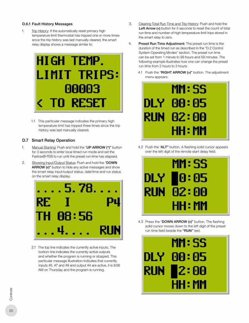
1. Trip History: If the automatically reset primary high temperature limit thermostat has tripped one or more times since the trip history was last manually cleared, the smart relay display shows a message similar to:
1.1 This particular message indicates the primary high temperature limit has tripped three times since the trip history was last manually cleared.
D.7 Smart Relay Operation
1. Manual Starting: Push and hold the “UP ARROW (̂ )” button for 3 seconds to enter local timed run mode and set the Fastrax® FEB to run until the preset run time has elapsed.
2. Showing Input/Output Status: Push and hold the “DOWN ARROW (v)” button to hide any active messages and show the smart relay input/output status, date/time and run status on the smart relay display:
2.1 The top line indicates the currently active inputs. The bottom line indicates the currently active outputs and whether the program is running or stopped. This particular message illustration indicates that currently inputs #5, #7 and #8 and output #4 are active, it is 8:56 AM on Thursday and the program is running.
3. Clearing Total Run Time and Trip History: Push and hold the Left Arrow (<) button for 5 seconds to reset the count of total run time and number of high temperature limit trips stored in the smart relay to zero.
4. Preset Run Time Adjustment: The preset run time is the duration of the timed run as described in the “D.2 Control System Operating Modes” section. The preset run time can be set from 1 minute to 99 hours and 59 minutes. The following example illustrates how one can change the preset run time from 2 hours to 3 hours:
4.1 Push the “RIGHT ARROW (>)” button. The adjustment menu appears.
4.2 Push the “ALT” button. A flashing solid cursor appears over the left digit of the remote start delay field.
4.3 Press the “DOWN ARROW (v)” button. The flashing solid cursor moves down to the left digit of the preset run time field beside the “RUN” text.

21
Controls
4.4 Push the “OK” button. The left digit of the preset run time field begins to flash.
4.5 Adjust the preset run time in HH:MM format.
4.5.1 Using the “LEFT ARROW (<)” and “RIGHT ARROW (>)” buttons, move the cursor to the digit to be changed. Using the “UP ARROW (̂ )” and “DOWN ARROW (v)” buttons, adjust the value of the digit at the cursor position.
4.6 Push the “OK” Button. The entered preset run time is saved and the solid cursor begins flashing again.
4.7 Push the “ESC” Button. The cursor disappears.
4.8 Push the “DOWN BUTTON (v)”. The adjustment menu disappears.
5. Start Delay Adjustment: The remote start delay is the duration that the Fastrax® FEB will wait before starting after the remote start contacts are held closed, snow is detected or the unit is power cycled during a run. The delay can be set from 0 seconds to 99 minutes and 59 seconds.
The following example illustrates how one can change the remote start delay from 5 seconds to 10 seconds:
5.1 Push the “RIGHT ARROW (>)”. The adjustment menu appears.

22
Con
trol
s
5.2 Push the “ALT” button. A flashing solid cursor appears over the left digit of the remote start delay field beside the “DLY” text.
5.3 Push the “OK” button. The left digit of the remote start delay field begins to flash.
5.4 Adjust the remote start delay to the right of the “DLY” text in MM:SS format.
5.4.1 Using the “LEFT ARROW (<)” and “RIGHT ARROW (>)” buttons, move the cursor to the digit to be changed. Using the “UP ARROW (̂ )” and “DOWN ARROW (v)” buttons, adjust the value of the digit at the cursor position.
5.5 Push the “OK” Button. The entered remote start delay is saved and the solid cursor begins flashing again.

23
Controls
5.6 Push the “ESC” Button. The cursor disappears.
5.7 Push the “DOWN BUTTON (V)”. The adjustment menu disappears.
D.8 Protection
1. Primary High Temperature Limit Thermostat: The purpose of this device is to provide a first line of defense against overheating conditions that could otherwise cause equipment damage or failure. If there is an issue with the installation of the Fastrax® FEB motor, such as a significant airflow restriction or a malfunctioning blower, the heating elements and ducting downstream of the elements could run at an elevated temperature. If this temperature is sufficiently high to be of concern, the primary high temperature limit thermostat contacts should open, de-energizing the duct heater elements to allow the Fastrax® FEB to cool down. Once the Fastrax® FEB has cooled sufficiently, the primary high temperature limit thermostat contacts should automatically reclose and the duct heater elements should re-energize. If the cause of the overheating condition is transient and goes away on its own, then the Fastrax® FEB will go back to operating as it should. If, on the other hand, the cause of the overheating condition is not rectified, the Fastrax® FEB will continue to alternate between energizing and de-energizing the duct heater elements during operation until cold air mode is forced on indefinitely, which could negatively impact snow clearing performance.
2. Backup High Temperature Limit Thermostat: The purpose of this device is to provide a second line of defense against overheating conditions that could otherwise cause equipment damage. If there is an extreme overheating condition that causes the equipment to run at a much higher temperature than the threshold of the primary high temperature limit, or if the primary high temperature limit has malfunctioned, then the backup high temperature limit thermostat contacts should open, de-energizing the duct heater elements to allow the Fastrax® FEB to cool down. The contacts of the backup high temperature limit thermostat will remain open and prevent the duct heater elements from energizing until this thermostat is manually reset. The backup high temperature limit thermostat should only be manually reset if the heater has been thoroughly checked and evaluated to be in proper working order.
3. Motor Controller: The purpose of this device is to protect the motor from medium and long term overcurrent conditions that could otherwise damage it and result in a costly replacement. There are many common causes of motor overloads that must be mitigated, including excessive loading on the blower impeller due to clogged ducting or bearing friction. The class 10 tripping characteristic curve of the motor controller has been carefully designed to prevent degradation of the motor windings in these overload conditions. Without this protection, the otherwise long life of the motor could be cut short if an overload occurs.
4. Circuit Breakers: The purpose of these devices is to protect and isolate the Fastrax® FEB electrical components including the controls and duct heater elements from short term overcurrent conditions and from line and ground faults. The codes printed on the labels of these breakers and their corresponding functions are listed in the table found in subsection D.9 Control Panel Layout.
4.1 In the event of a fault, one of these breakers should trip, disconnecting the faulted circuit from the rest of the Fastrax® FEB’s circuits. After the fault is cleared and its underlying cause is resolved, this breaker must be manually reset to restore normal operation.
D.9 Smart Relay Inputs and Outputs
1. Inputs:
1.1 “MANUAL START” push-button
1.2 Aerial snow sensor
1.3 Ground snow sensor
1.4 Remote Start/Stop contacts
1.5 “MANUAL STOP” push-button
1.6 “COLD AIR MODE” selector switch
1.7 Primary high temperature limit trip feedback
1.8 Backup high temperature limit trip feedback
1.9 Motor controller feedback
1.10 Snow sensor circuit breaker trip feedback
1.11 “REMOTE TIMEOUT MODE” selector switch
2. Outputs:
2.1 Blower contactor control coil
2.2 Heater contactor control coil
2.3 Backup high temperature limit trip indication
2.4 System fault indication

24
Con
trol
s
D.10 Control Panel Layout
FunctionCircuit Breaker Label
208V 240V 480V 600V
Blower Motor MS208-1 MS240-1 MS480-1 MS600-1
Duct Heater Elements
CB208-1 CB240-1 CB480-1 CB600-1
Transformer Breaker CB208-2 CB240-2 CB480-2 CB600-2
Control Circuit CB24-1 CB24-1 CB24-1 CB24-1
Aerial Snow Sensor CB24-2 CB24-2 CB24-2 CB24-2
Ground Snow Sensor CB24-3 CB24-3 CB24-3 CB24-3
Smart RelayControl Relay
Control Transformer
Control Circuit Breaker Aerial Snow Sensor Breaker
Ground Snow Sensor BreakerDuct Heater Contactor
Supply Line Entry
Disconnect Switch
Duct Heater Circuit Breaker Motor Contactor
Customer Remote Signal Connections
Combination Motor Starter
Transformer Breaker

25
Initial Start-up/C
omm
issioning & Q
uick Start G
uide
E. INITIAL STARTUP/COMMISSIONING
1. Ensure there is no snow or moisture on the snow sensor sensing heads and the remote start signals are inactive.
NOTE: If keeping the remote start signal inactive is impractical, temporarily disconnect the field wiring from the remote start/stop terminals RSS-1 and RSS-2.
2. Open the outer enclosure door to reveal the operator interface on the control panel door.
3. On the control panel door, close the disconnect switch. The white “CONTROL ON” and red “SYSTEM FAULT” pilot lights should illuminate. After about 5 seconds the
“SYSTEM FAULT” pilot light should turn off.
4. The unit should now be idle in standby mode.
5. During steps E.6 to E.15, monitor the “SYSTEM FAULT” and “HIGH TEMP LIMIT” pilot lights and verify these lights remain off.
6. Set the “COLD AIR MODE” selector switch to “OFF”, to set the blower into “HOT AIR MODE”.
7. Push and hold the red “MANUAL START” button for 3 seconds.
8. Verify blower operation with illumination of the green “BLOWER ON” and green “HEAT ON” pilot lights. For three phase units verify the motor rotation is correct according to the directional arrow on the motor fan cover or the arrow cast into the blower housing. Interchange the supply line conductors if correction is required.
Failure to verify correct blower rotation will cause damage to the heater and void the warranty.
WARNINGWARNING
9. After waiting about 3 minutes for the unit to warm up, ensure the air discharged from the point nozzles feels warm.
10. Set the “COLD AIR MODE” selector switch to “ON”, to set the blower into cold air mode.
11. Verify the blower continues to run, the green “BLOWER ON” pilot light remains illuminated and the green “HEAT ON” pilot light turns off.
12. After waiting about 3 minutes for the unit to cool down, ensure the air discharged from the point nozzles feels cool.
13. Push the red “MANUAL STOP” button. Verify the blower stops and the green “BLOWER ON” and green “HEAT ON” pilot lights are both off.
14. Ensure the aerial and ground snow sensors activate the blower by adding snow to either sensor when it is below 40°F (4°C). The unit will automatically turn on after a period of 10 to 30 seconds. If no snow is present use a can of aerosol freeze spray and add water to the locations detailed in Section H.18 Fall Maintenance.
15. Using the “COLD AIR MODE” and “REMOTE TIMEOUT MODE” selector switches, set the blower into the desired modes for the installation.
F. QUICK START GUIDE
1. Turn the disconnect switch to “ON” and wait a few seconds for the red “SYSTEM FAULT” light to turn off.
2. During steps F.3 to F.6, monitor the red “SYSTEM FAULT” and “HIGH TEMP” lights to ensure they remain off.
3. Make sure the unit does not run automatically (snow not detected).
4. Push the start button and verify the unit starts. The Fastrax® FEB will run for 2 hours in timed run mode unless snow is detected.
5. To shut down the Fastrax® FEB, switch to “COLD AIR MODE” for a few minutes to cool the unit down.
6. Push the manual stop button and verify that the unit stops.
26
Trou
bles
hoot
ing
- G
ener
al
G. TROUBLESHOOTING
Chart A: Troubleshooting - General
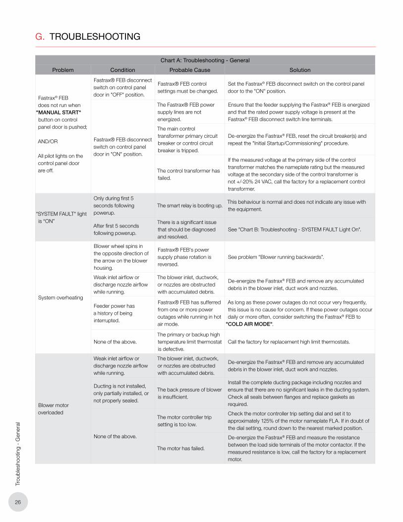
Problem Condition Probable Cause Solution
Fastrax® FEB does not run when
"MANUAL START" button on control panel door is pushed; AND/OR All pilot lights on the control panel door are off.
Fastrax® FEB disconnect switch on control panel door in "OFF" position.
Fastrax® FEB control settings must be changed.
Set the Fastrax® FEB disconnect switch on the control panel door to the "ON" position.
Fastrax® FEB disconnect switch on control panel door in "ON" position.
The Fastrax® FEB power supply lines are not energized.
Ensure that the feeder supplying the Fastrax® FEB is energized and that the rated power supply voltage is present at the Fastrax® FEB disconnect switch line terminals.
The main control transformer primary circuit breaker or control circuit breaker is tripped.
De-energize the Fastrax® FEB, reset the circuit breaker(s) and repeat the "Initial Startup/Commissioning" procedure.
The control transformer has failed.
If the measured voltage at the primary side of the control transformer matches the nameplate rating but the measured voltage at the secondary side of the control transformer is not +/-20% 24 VAC, call the factory for a replacement control transformer.
"SYSTEM FAULT" light is “ON”
Only during first 5 seconds following powerup.
The smart relay is booting up.This behaviour is normal and does not indicate any issue with the equipment.
After first 5 seconds following powerup.
There is a significant issue that should be diagnosed and resolved.
See "Chart B: Troubleshooting - SYSTEM FAULT Light On".
System overheating
Blower wheel spins in the opposite direction of the arrow on the blower housing.
Fastrax® FEB's power supply phase rotation is reversed.
See problem "Blower running backwards”.
Weak inlet airflow or discharge nozzle airflow while running.
The blower inlet, ductwork, or nozzles are obstructed with accumulated debris.
De-energize the Fastrax® FEB and remove any accumulated debris in the blower inlet, duct work and nozzles.
Feeder power has a history of being interrupted.
Fastrax® FEB has sufferred from one or more power outages while running in hot air mode.
As long as these power outages do not occur very frequently, this issue is no cause for concern. If these power outages occur daily or more often, consider switching the Fastrax® FEB to
"COLD AIR MODE".
None of the above.The primary or backup high temperature limit thermostat is defective.
Call the factory for replacement high limit thermostats.
Blower motor overloaded
Weak inlet airflow or discharge nozzle airflow while running.
The blower inlet, ductwork, or nozzles are obstructed with accumulated debris.
De-energize the Fastrax® FEB and remove any accumulated debris in the blower inlet, duct work and nozzles.
Ducting is not installed, only partially installed, or not properly sealed.
The back pressure of blower is insufficient.
Install the complete ducting package including nozzles and ensure that there are no significant leaks in the ducting system. Check all seals between flanges and replace gaskets as required.
None of the above.
The motor controller trip setting is too low.
Check the motor controller trip setting dial and set it to approximately 125% of the motor nameplate FLA. If in doubt of the dial setting, round down to the nearest marked position.
The motor has failed.
De-energize the Fastrax® FEB and measure the resistance between the load side terminals of the motor contactor. If the measured resistance is low, call the factory for a replacement motor.

27
Troubleshooting - General
Chart A: Troubleshooting - General
Problem Condition Probable Cause Solution
Cold air discharged
while running but hot
air is desired
Fastrax® FEB selector
switch on control panel
door is set to "COLD AIR
MODE".
Fastrax® FEB control
settings must be changed.
Set the selector switch on the control panel door to "HOT AIR
MODE”.
Fastrax® FEB selector
switch on control panel
door is set to "HOT AIR
MODE" and "SYSTEM
FAULT" light is “OFF”.
One or more heater circuit
breakers are tripped.
De-energize the Fastrax® FEB, reset the heater circuit breakers
and repeat the "Initial Startup/Commissioning" procedure.
Fastrax® FEB heater circuit
wiring connections are
loose.
De-energize the Fastrax® FEB and check for loose wiring
connections in the heater element circuits.
One or more Fastrax® FEB
heater elements have failed.
De-energize the Fastrax® FEB and check the resistance at
each of the heater contactor load side terminals against the
Element Resistance Table - H.1 Fall Maintenance secton. If the
measured resistance is out of specification, call the factory for
replacement heating elements.
Blower running
backwards
Blower wheel spins in
the opposite direction of
the arrow on the blower
housing AND Fastrax®
FEB model is rated for 3
phase supply power.
The Fastrax® FEB's power
supply phase rotation is
reversed.
De-energize the Fastrax® FEB and interchange two of the load
side leads at the Fastrax® FEB disconnect switch. For instance,
this interchanging can be achieved by connecting the lead
initially at T1 to T2 and connecting the lead initially at T2 to T1.
Excessive motor
vibration
Blower wheel is loose.A blower wheel fastener has
loosened over time.
De-energize the Fastrax® FEB and manually check the blower
wheel for play. If it is loose, tighten the blower wheel shaft
fastener.
Blower wheel is
unbalanced.
Ice or other foreign material
has accumulated on the
blower wheel.
De-energize the Fastrax® FEB and clean the blower wheel.
Blower wheel fins are
cracked or broken.Call the factory for a replacement blower wheel.
Blower wheel seems fine.
Blower wheel spins in
the opposite direction of
the arrow on the blower
housing.
See problem "Blower running backwards”.
A motor bearing has failed. Call the factory for a replacement motor.

28
Trou
bles
hoot
ing
- G
ener
al
Chart B: Troubleshooting - System Fault Light “ON”
Smart Relay Display Message
Condition Probable Cause Solution
PRIMARY HIGH
TEMPERATURE LIMIT
TRIPPED!
Message shows
intermittently while
running with "HOT AIR
MODE" selected.
The primary high
temperature limit
thermostat has tripped due
to overheating.
See problem "System overheating" in Chart A:
Troubleshooting - General.
Message shows
permanently.
There is a poor connection
in the of primary high
temperature limit
thermostat or relay wiring.
De-energize the Fastrax® FEB, check for loose wiring
connections and tighten as needed.
The primary high
temperature limit
thermostat or other another
related component has
failed.
De-energize the Fastrax® FEB, disconnect the primary
thermostat quick disconnect terminals and check the
resistance between the thermostat terminals.
If the measured resistance is greater than 5 Ω, call the
factory for a replacement thermostat.
If the measured resistance is lower than 5 Ω, call the factory
for further assistance."
COLD AIR MODE
FORCED!
PUSH START TO
RESET
Message shows
permanently AND air at
discharge nozzles is cold
while running regardless
of whether "COLD AIR
MODE" or "HOT AIR
MODE" is selected.
The primary high
temperature limit
thermostat tripped more
than 10 times in one day
due to overheating.
Push the "MANUAL START" button on the control
panel door and repeat the "Initial Startup/Commissioning"
procedure.
Also, see problem “System overheating” in Chart A:
Troubleshooting - General.
BACKUP HIGH
TEMPERATURE LIMIT
TRIPPED!
Message shows
permanently AND
Red "HIGH TEMP LIMIT"
light is lit.
The backup high
temperature limit
thermostat has tripped due
to overheating.
De-energize the Fastrax® FEB, push the "HIGH LIMIT
RESET" button on the thermostat and repeat the "Initial
Startup/Commissioning" procedure.
If this message goes away after reseting but reappears
while running, see problem “System overheating” in Chart A:
Troubleshooting - General.
There is a poor connection
in the of backup high
temperature limit
thermostat or relay wiring.
De-energize the Fastrax® FEB, check for loose wiring
connections and tighten as needed
The backup high
temperature limit
thermostat or other another
related component has
failed.
De-energize the Fastrax® FEB, disconnect the backup
thermostat quick disconnect terminals and check the
resistance between the thermostat terminals.
If the measured resistance is greater than 5 Ω, try applying
firm pressure to the "HIGH LIMIT RESET" button on the
thermostat (push hard). The thermostat should click while
being reset. If the measured resistance is still greater than 5
Ω, call the factory for a replacement thermostat.
If the measured resistance is lower than 5 Ω, call the factory
for further assistance.

29
Troubleshooting - General
Chart B: Troubleshooting - System Fault Light “ON”
Smart Relay Display Message
Condition Probable Cause Solution
BLOWER MOTOR
CONTROLLER
TRIPPED!
Message shows
permanently
The motor controller's
short circuit or overload
protection device has
tripped.
De-energize the Fastrax® FEB and check the motor
controller. If it has tripped, reset it and repeat "Initial Startup/
Commissioning" procedure.
Also, see problem "Blower motor overloaded" in Chart A:
Troubleshooting - General.
SNOW SENSOR
CIRCUIT BREAKER
TRIPPED!
Message shows
permanently.
The aerial snow sensor
circuit breaker, ground
snow sensor circuit breaker,
or both have tripped.
De-energize the Fastrax® FEB and reset all snow sensor
breakers. Repeat the "Initial Startup/Commissioning"
procedure.
If a snow sensor breaker trips again, call the factory for a
replacement snow sensor.
AERIAL SNOW
SENSOR BAD! PUSH
START TO RESET
AND/OR
GROUND SNOW
SENSOR BAD! PUSH
START TO RESET
Message shows
permanently AND
Fastrax® FEB does not
respond to snow on
indicated snow sensor.
The aerial or ground snow
sensor in the indicated
circuit has failed with it's
snow sensing contacts
permanently closed.
De-energize the Fastrax® FEB, disconnect the bad snow
sensor indicated by the message. The control panel SSA-1
and SSA-2 terminals correspond to the aerial snow sensor
while the SSG-1 and SSG-2 terminals correspond to the
ground snow sensor.
Repeat the "Initial Startup/Commissioning" procedure. If
this message disappears and the Fastrax® FEB operates as
it should except for the disconnected snow sensor, call the
factory for replacement of the disconnected snow sensor(s).
HIGH TEMP LIMIT
TRIPS: ##### < TO
RESET
Message shows
permanently.
The primary high
temperature limit
thermostat tripped at least
once since the trip count
was last cleared.
See problem "System overheating" in Chart A:
Troubleshooting - General.
If the problem is resolved, push and hold the "<" button on
the smart relay to reset the trip count.
Smart relay status
screen showing active
input numbers in top
row, date/time in middle,
and active output
numbers in bottom row
Message shows
permanently.
The smart relay program is
not present or not running.Call the factory for assistance.
Blank
Nothing displayed on
smart relay screen but
white "CONTROL ON"
light is lit.
The smart relay has failed. Call the factory for a replacement smart relay.

30
Ele
ctric
Blo
wer
Sea
sona
l Mai
nten
ance
H. ELECTRIC BLOWER SEASONAL MAINTENANCE
Disconnect heater from power supply at integral disconnect or fuse box before opening enclosures or servicing heater.
Lock the switch in the “OFF” (open) position and tag the switch to prevent unexpected power application.
This heater should only be serviced by qualified personnel with electrical heating equipment experience.
Install and use the heater in accordance with local codes and this Owner’s Manual.
WARNINGWARNING
H.1 Fall Maintenance (Before Heating Season)
1. Inspect all duct work, nozzles and flexible duct for internal debris and physical damage. Manually remove any accumulation of foreign matter or obstructions from the duct work and nozzles.
2. Replace any duct components showing signs of physical damage or excessive corrosion.
3. Verify the electrical isolation of the two distribution duct sections using a multimeter and checking for lack of continuity.
4. If the unit has been placed in storage be sure to remove the discharge blanking plate prior to attaching the flex duct connection.
5. Ensure the disconnect switch is set to the “OFF” position and locked out prior to inspecting the duct heater and blower for accumulations of foreign matter, physical damage or excessive corrosion. All deficiencies must be corrected before the unit can be placed in service.
6. Manually turn the blower wheel to ensure it rotates freely and there is no bearing noise from the electric motor.
7. Ensure the disconnect switch is set to the “OFF” position and locked out. Inspect for loose, damaged or frayed wiring. Inspect for burned or overheated connections. Replace any damaged electrical components. Correct any deficiencies before proceeding. Retighten all electrical connections to the proper torque specifications listed in Section B.2 Torque Specifications.
8. Remove the cover from the duct heater terminal box and inspect for moisture and corrosion. If conditions are acceptable, check all bus bar connections for proper torque specifications listed in Section B.2 Torque Specifications.
9. Check electrical cables for proper connection to the bus bars and ensure all fasteners are properly secured.
10. Using a multimeter, verify the resistance across the bank of elements from the load side of the element contactor. Any significant deviation from the element resistance table should be investigated as this would suggest one or more elements are open or in short circuit.
Element Resistance
kW Volts PhMin.
Resistance/LegMax. Resistance/
Leg
20
208 1 1.9 2.4
208 3 3.9 4.8
240 1 2.6 3.2
240 3 5.1 6.5
480 1 10.3 12.9
480
3
20.6 25.8
600 32.1 40.3
40/60480 20.6 25.8
600 32.1 40.3
11. Inspect cover gasket and repair any defects prior to replacing the electrical cover.
12. Enable line power. Using a multimeter, confirm the supply voltage is correct and within acceptable tolerances according to Section B.10-6.
13. Set the disconnect switch in the control panel to the “ON” position, set the Fastrax® FEB to “COLD AIR MODE” and test for correct blower rotation by starting the blower using the “MANUAL START” button. If motor rotation is incorrect, reverse the phase alignment and verify correct rotation.
14. Using a current clamp, measure the current draw on the motor and confirm it is within the Full Load Amps rating of the motor as shown on the motor data plate.
15. During the motor run test, make note of any excessive vibration or bearing noise.
15.1 Address blower imbalance by replacing the blower wheel.
15.2 Address bearing failure by replacing the motor.
16. Grease the front and back bearings of the electric motor using a grease gun and a low temperature grease such as Arrowshell 7 or Mobile 28.
Do not over grease, 0.5 grams or 1 pump in each grease fitting will be adequate.
CAUTIONCAUTION
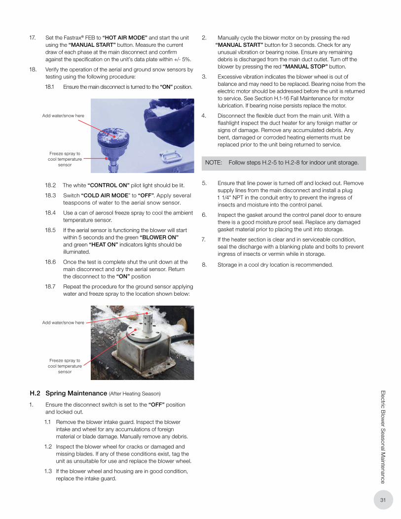
31
Electric B
lower S
easonal Maintenance
17. Set the Fastrax® FEB to “HOT AIR MODE” and start the unit using the “MANUAL START” button. Measure the current draw of each phase at the main disconnect and confirm against the specification on the unit’s data plate within +/- 5%.
18. Verify the operation of the aerial and ground snow sensors by testing using the following procedure:
18.1 Ensure the main disconnect is turned to the “ON” position.
Freeze spray to cool temperature
sensor
Add water/snow here
18.2 The white “CONTROL ON” pilot light should be lit.
18.3 Switch “COLD AIR MODE” to “OFF”. Apply several teaspoons of water to the aerial snow sensor.
18.4 Use a can of aerosol freeze spray to cool the ambient temperature sensor.
18.5 If the aerial sensor is functioning the blower will start within 5 seconds and the green “BLOWER ON” and green “HEAT ON” indicators lights should be illuminated.
18.6 Once the test is complete shut the unit down at the main disconnect and dry the aerial sensor. Return the disconnect to the “ON” position
18.7 Repeat the procedure for the ground sensor applying water and freeze spray to the location shown below:
Freeze spray to cool temperature
sensor
Add water/snow here
H.2 Spring Maintenance (After Heating Season)
1. Ensure the disconnect switch is set to the “OFF” position and locked out.
1.1 Remove the blower intake guard. Inspect the blower intake and wheel for any accumulations of foreign material or blade damage. Manually remove any debris.
1.2 Inspect the blower wheel for cracks or damaged and missing blades. If any of these conditions exist, tag the unit as unsuitable for use and replace the blower wheel.
1.3 If the blower wheel and housing are in good condition, replace the intake guard.
2. Manually cycle the blower motor on by pressing the red “MANUAL START” button for 3 seconds. Check for any unusual vibration or bearing noise. Ensure any remaining debris is discharged from the main duct outlet. Turn off the blower by pressing the red “MANUAL STOP” button.
3. Excessive vibration indicates the blower wheel is out of balance and may need to be replaced. Bearing noise from the electric motor should be addressed before the unit is returned to service. See Section H.1-16 Fall Maintenance for motor lubrication. If bearing noise persists replace the motor.
4. Disconnect the flexible duct from the main unit. With a flashlight inspect the duct heater for any foreign matter or signs of damage. Remove any accumulated debris. Any bent, damaged or corroded heating elements must be replaced prior to the unit being returned to service.
NOTE: Follow steps H.2-5 to H.2-8 for indoor unit storage.
5. Ensure that line power is turned off and locked out. Remove supply lines from the main disconnect and install a plug 1 1/4" NPT in the conduit entry to prevent the ingress of insects and moisture into the control panel.
6. Inspect the gasket around the control panel door to ensure there is a good moisture proof seal. Replace any damaged gasket material prior to placing the unit into storage.
7. If the heater section is clear and in serviceable condition, seal the discharge with a blanking plate and bolts to prevent ingress of insects or vermin while in storage.
8. Storage in a cool dry location is recommended.

32
Par
ts A
ssem
bly
Dia
gram
s
Item #Description Part Numbers
20 kW
1 Transition Duct 12917
2 Gasket for Transition Duct 13016
3 Element Bundle Contact Factory
4 Element Gasket 13017
5 Backup High Temperature Limit 13015
6 Primary High Temperature Limit 13014
7 Blower Wheel Contact Factory
8
Motor, 240V, 1 Phase, 3HP 13008
240V, 3 Phase, 3HP 12901
480V, 1 Phase, 3HP 13009
480V, 3 Phase, 3HP 12901
575V, 3 Phase, 3HP 13010
9 Aerial Snow Sensor FAS1A
10 Back Panel 12891
11 Air Intake Side Panel, Low Profile 12888
12 Side Panel, Control Panel 12889
13 Control Panel Access Door 12894
14 Front Panel 12892
15 Ground Snow Sensor FGSP1A
16 Top Panel, Hinged 12893
17 Blower Assembly 12890
16
4
1
3
14
5
6
211
17
15
8
7
9
10
13
12
I. PART ASSEMBLY DIAGRAMS
I.1 Fastrax® FEB Electric Hot Air Blower Parts List - 20 kW

33
Parts A
ssembly D
iagrams
I.2 Fastrax® FEB Electric Hot Air Blower Parts List - 40/60 kW
17
17
17
Item # DescriptionPart Numbers
40/60 kW
1 Transition Duct 13018
2 Gasket for Transition Duct 13016
3 Element Bundle Contact Factory
4 Element Gasket 13034
5 Backup High Temperature Limit 13015
6 Primary High Temperature Limit 13014
7 Blower Wheel Contact Factory
8480V, 3 Phase, 7.5HP 13012
575V, 3 Phase, 7.5HP 13013
9 Aerial Snow Sensor FAS1A
10 Back Panel 13019
11 Air Intake Side Panel, Low Profile 13020
12 Side Panel, Control Panel 13021
13 Control Panel Access Door 13022
14 Front Panel 13023
15 Ground Snow Sensor FGSP1A
16 Top Panel, Hinged 13024
17 Blower Assembly 13126
4
3
14
5
6 212
16
9
10
11
15
13
8
7
1

34
Par
ts A
ssem
bly
Dia
gram
s
Item # DescriptionPart Numbers
20kW, 3 PH, 600V
1 Smart Relay FDC-7
2 Duct Heater Contactor 13165
3 Motor Contactor 13165
4 Disconnect Switch OT63F3
5 Control Relay RCP8002 24AC
6 Circuit Breaker - Control Transformer 13162
7 Circuit Breaker - 24V Control Circuit SU201M-C3
8 Circuit Breaker - Aerial Snow Sensor SU201M-C2
9 Circuit Breaker - Ground Snow Sensor SU201M-C4
10 Circuit Breaker - Duct Heater 12085-25
11 Combination Manual Motor Starter 13164
12 Control Transformer 13170
13 Auxiliary Contact - Combination Manual Motor Starter 13171
14 Auxiliary Contact - Circuit Breaker Snow Sensors S2C-H6RU
15 Auxiliary Contact - Motor Contactor 13166
16* Pilot Light Lens - White 13160
17* Pilot Light Lens - Green 13156
18* Pilot Light Lens - Red 13159
19* Selector Switch 13152
20* Push Button - Red 13155
21* LED Pilot Light 13158
22* Disconnect Switch Handle OHB65L6
Note: Control circuit components may be substituted with other equivalent parts from factory.
*Not shown
Supply Line Entry
Customer Remote Signal Connections
7, 8, 9, 14
12
3, 15
11
5 1
2
10
4
I.3 Control Panel Parts List
6
13
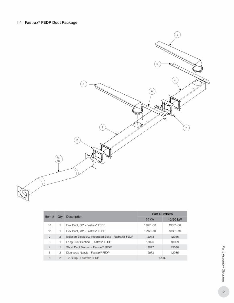
35
Parts A
ssembly D
iagrams
Item # Qty DescriptionPart Numbers
20 kW 40/60 kW
1a 1 Flex Duct, 60" - Fastrax® FEDP 12971-60 13031-60
1b 1 Flex Duct, 70" - Fastrax® FEDP 12971-70 13031-70
2 2 Isolation Block c/w Integrated Bolts - Fastrax® FEDP 12983 12986
3 1 Long Duct Section - Fastrax® FEDP 13026 13029
4 1 Short Duct Section - Fastrax® FEDP 13027 13030
5 2 Discharge Nozzle - Fastrax® FEDP 12973 12985
6 2 Tie Strap - Fastrax® FEDP 12982
2
2
3
1a, 1b
5
6
4
6
5
I.4 Fastrax® FEDP Duct Package

J.
Oakville
1-800-410-3131
1-905-829-4422
F 905-829-4430
Orillia
1-877-325-3473
1-705-325-3473
F 705-325-2106
WARRANTY: Under normal use the Company warrants
to the purchaser that defects in material or workmanship will
be repaired or replaced without charge for a period of 36
months from date of shipment. Any claim for warranty must be
reported to the sales office where the product was purchased
for authorized repair or replacement within the terms of this
warranty.
Subject to State or Provincial law to the contrary, the Company
will not be responsible for any expense for installation, removal
from service, transportation, or damages of any type whatsoever,
including damages arising from lack of use, business interruptions,
or incidental or consequential damages.
The Company cannot anticipate or control the conditions of
product usage and therefore accepts no responsibility for
the safe application and suitability of its products when used
alone or in combination with other products. Tests for the
safe application and suitability of the products are the sole
responsibility of the user.
This warranty will be void if, in the judgment of the Company, the
damage, failure or defect is the result of:
• Vibration, radiation, erosion, corrosion, process con -
tamination, abnormal process conditions, temperature and
pressures, unusual surges or pulsation, fouling, ordinary
wear and tear, lack of maintenance, incorrectly applied
utilities such as voltage, air, gas, water, and others or any
combination of the aforementioned causes not specifically
allowed for in the design conditions or,
• Any act or omission by the Purchaser, its agents, servants
or independent contractors which for greater certainty, but
not so as to limit the generality of the foregoing, includes
physical, chemical or mechanical abuse, accident,
improper installation of the product, improper storage
and handling of the product, improper application or the
misalignment of parts.
No warranty applies to paint finishes except for manufacturing
defects apparent within 30 days from the date of installation.
The Company neither assumes nor authorizes any person to assume for it
any other obligation or liability in connection with the product(s).
The Purchaser agrees that all warranty work required after the initial
commissioning of the product will be provided only if the Company
has been paid by the Purchaser in full accordance with the terms and
conditions of the contract.
The Purchaser agrees that the Company makes no warranty or
guarantee, express, implied or statutory, (including any warranty of
merchantability or warranty of fitness for a particular purpose) written
or oral, of the Article or incidental labour, except as is expressed or
contained in the agreement herein.
LIABILITY: Technical data contained in the catalog or on the
website is subject to change without notice. The Company reserves
the right to make dimensional and other design changes as required.
The Purchaser acknowledges the Company shall not be obligated
to modify those articles manufactured before the formulation of the
changes in design or improvements of the products by the Company.
The Company shall not be liable to compensate or indemnify the
Purchaser, end user or any other party against any actions, claims,
liabilities, injury, loss, loss of use, loss of business, damages, indirect
or consequential damages, demands, penalties, fines, expenses
(including legal expenses), costs, obligations and causes of action of
any kind arising wholly or partly from negligence or omission of the
user or the misuse, incorrect application, unsafe application, incorrect
storage and handling, incorrect installation, lack of maintenance,
improper maintenance or improper operation of products furnished
by the Company.
Edmonton (Head Office)
1-780-466-3178
F 780-468-5904
5918 Roper Road
Alberta, Canada T6B 3E1
Houston
1-855-219-2101
1-281-506-2310
F 281-506-2316
Denver
1-303-979-7339
F 303-979-7350
PLEASE ADHERE TO INSTRUCTIONS IN THIS MANUAL
Failure to do so may be dangerous and may void certain provisions
of your warranty.
For further assistance, please call 24hr hotline: 1-855-244-3128 (U.S.A. and Canada)
Please have model and serial numbers available before calling.