installation, operation and maintenance durco … · durco microfinish section 1.0™ ball ......
TRANSCRIPT

Flow Control Division
Section 1.0Durco Microfinish ™
Ball ValvesF O R C H E M I C A L S E R V I C E S
The Best Standard Stem Seal In The Industry
Quality System
Certificate
Bulletin VM-60-100a (E)
Installation, Operation and Maintenance

TABLE OF CONTENTS
Flow Control Division
Section 1.0
1.0 Prior to Installation . . . . . . . . . . . . . . . . . . . . . . . . 3
2.0 Installation . . . . . . . . . . . . . . . . . . . . . . . . . . . . . . 4
3.0 Operation and Maintenance . . . . . . . . . . . . . . . . . . 5
4.0 Disassembly . . . . . . . . . . . . . . . . . . . . . . . . . . . . . 5
5.0 Assembly – 2-Piece Valves . . . . . . . . . . . . . . . . . . 6
6.0 Assembly – 3-Piece Valves . . . . . . . . . . . . . . . . . . 7
Table 1. . . . . . . . . . . . . . . . . . . . . . . . . . . . . . . . . . . . . 8
Table 2. . . . . . . . . . . . . . . . . . . . . . . . . . . . . . . . . . . . . 8
Table 3. . . . . . . . . . . . . . . . . . . . . . . . . . . . . . . . . . . . . 9
Table 4. . . . . . . . . . . . . . . . . . . . . . . . . . . . . . . . . . . . . 9
Table 5. . . . . . . . . . . . . . . . . . . . . . . . . . . . . . . . . . . . . 9
Table 6. . . . . . . . . . . . . . . . . . . . . . . . . . . . . . . . . . . . 10
Table 7. . . . . . . . . . . . . . . . . . . . . . . . . . . . . . . . . . . . 10

3
SECTION 1.0
PRIOR TO INSTALLATION
Flow Control Division
Section 1.0
1.1 The practical and safe use of this product is determined byboth the seat and body ratings. Read the identification plateand check both ratings. This product is available with avariety of seat materials. Some of these seat materials havepressure ratings that are less than the body ratings. All of thebody and seat ratings are dependent on valve type and size,bolting material and temperature. Do not exceed theseratings, damage or personnel injury may result.
1.2 Check that the valve and its accessories have not beendamaged during transportation.
1.3 Any wrapping, tagging, or protection applied should be leftin place until the valve is installed.
1.4 If the valves are left exposed, they should be protectedagainst entry of foreign material in the valve parts.
1.5 If the valves are stored for an extended period of time, theyshould be cleaned, lubricated, and tested prior to installation.Valves should be stored in the full open position.
1.6 Flush the pipe clean before mounting the valve. Impuritiessuch as sand and parts of welding electrodes could damagethe ball surface and the seats.
1.7 In lever operated valves, the position of the handle is anindication of whether the valve is open or closed. When thehandle is aligned with the axis of the pipe the valve is open,when it is normal to the pipe the valve is closed.

SECTION 2.0
INSTALLATION
4
Flow Control Division
Section 1.0
2.1 Be sure that flange gaskets and fasteners are suitable for theoperating conditions.
2.2 The standard valve can be mounted in any convenient posi-tion, preferably with easy access to the packing gland nut,actuator, and positioners. The preferred stem orientation ishorizontal.
2.3 Do not attempt to correct flange or pipe misalignment bymeans of the valve body or flange bolts.
2.4 Valves should not carry the weight of the piping. Proper sup-port of the pipeline will minimize strain on the valve causedby shock in the pipe system. The valve can be supported byits body with pipe clamps and supports. Do not fasten sup-porting structure to the flange bolts or actuators.
2.5 Tighten the packing gland uniformly before installing and afterthe trial operation of the valve. (See Table 5)
2.6 When installing the Screwed End, Socket Weld End, andFlanged End type valves the following respective proceduresmust be followed for better performance.
2.7 Screwed End Installation
2.7a Avoid undersized threads on section of pipe where thevalves are to be installed.
2.7b Clean both the mating parts before assembly.
2.7c Paint, grease or sealant should be applied only to thepipe or male threads.
2.7d Use correct size wrenches with flat jaws on hexagonor octagon ends.
2.8 Socket Weld End Installation
2.8a The valve should be inspected prior to welding toassure that no foreign materials obstruct the flowpassageway and that the weld preparations are freeof corrosion and physical damage.
2.8b All welding operations must be done by a qualifiedwelder and the welding procedure shall be accordingto ASME boiler and pressure vessel code Section IX.
2.8c The valve should be in the full open position whilebeing welded.
2.8d Provide adequate support to the pipe on each side orto the valve prior to welding.
2.8e The valve body temperature should not exceed 120degrees C (250 degrees F) in the body seat area dur-ing welding; including preheats, interpasses, or postweld heat treatments as applicable.
Exceeding allowed temperature will result in seat, packing and bodygasket damage.
2.8f After finishing the welding operation, clean the pipelineand valve ports by flushing or pigging to remove theimpurities formed by welding.
2.9 Flanged End Installation
2.9a Insert the valve and proper gaskets between the mat-ing flanges. Align the flanges and valve. Note: Valveshould be installed in the open position.
2.9b Hold the nuts first on the backside of the valve flangeand then insert the bolts.
2.9c Tighten all bolts to finger tight.
2.9d Use two wrenches to tighten the joint in the sequenceshown in Figure 1. Tighten flange bolts per the gasketmanufacturer’s recommended practices.
2.9e Flush the pipe system carefully once the valve hasbeen installed to remove all possible impurities. Beforeflushing valve should remain in fully open position.
2.9f Re-tighten the packing if necessary until any leakagehas stopped.
WARNING
1
2
3
4
5
6
7
8
1
2
3
4
Figure 1Bolting Sequence Chart
4 HOLEFASTENERPATTERN
8 HOLEFASTENERPATTERN
1
2
3
4
5
6
7
8
9
10 11
12
12 HOLEFASTENERPATTERN

SECTION 3.0
OPERATION AND MAINTENANCE
SECTION 4.0
DISASSEMBLY
5
Flow Control Division
Section 1.0
3.1 Valves should be opened and closed slowly to avoidhammering effect on the valve and pipeline.
3.2 Valve should be “fully open” or “fully closed” to preventdamage to the seat and ball caused by wire drawing.
3.3 This valve is intended for on-off service and should not beused in throttling applications.
3.4 If a stem leak develops, tighten the gland nut until the leakagehas been stopped. If the stem leak cannot be stopped,replacement stem packing is available.
When replacing the packing, be sure that the valve is not underpressure. Remove all actuation to give access to the packing. Afterloosening and removing the gland nut, the packing can be removedby means of a hooked wire or a special purpose tool.
3.5 If a through leak occurs, ensure that the valve is fully closed.If leakage persists, replacement seats are available.
3.6 If a body seal leak develops, do not over tighten the body endcover bolting. This may damage the valve. Instead a replace-ment seal should be installed.
WARNING
4.1 Note: If complete disassembly becomes necessary, replace-ment of seats, packing, and bearing material is required.
4.2 For your safety and protection, it is important that the follow-ing precautions be taken prior to removing the valve fromservice or before any disassembly of the valve:A. At all times during this entire procedure, keep hands out
of the valve. A remotely actuated valve could close atany time and result in serious injury.
B. Know what media is in the line. If there is any doubt,check with the proper authority.
C. Wear any protective clothing or equipment normallyrequired when working with the media involved.
D. Depressurize the line and valve as follows: Open thevalve and drain the line. Close and open the valve torelieve any residual pressure that may be in the valveprior to removing the valve from service. Leave thevalve in the open position. After removal and prior toany disassembly, drain any remaining media by placingthe valve in a vertical position and carefully closing andopening the valve several times.
4.3 Support the valve on a platform.
4.4 Remove all accessories and adapter or lever nut and lever.
4.5 On 2 inch full bore and larger sizes remove stem nut lockscrew. On 2 inch reduced port and smaller sizes, removestem nut lock plate. Remove stem nut, spring washers,ground spring, and packing gland.
4.6 Mark the body joint flanges to assure correct body and tail-piece orientation during reassembly. Unscrew the body endconnection studs and separate the body and tailpiece(s).
4.7 Place the body and tailpiece(s) on a clean wood or cardboardsurface. Use care not to damage the mating surfaces of thebody or tailpiece(s).
4.8 Rotate the valve to the closed position and remove the ball. Usecare not to damage the surface of the ball during handling.
4.9 Take out the seat rings and body seal(s). Use care not todamage the sealing surfaces of the seat pocket. Note: on3-piece valves it may be necessary to remove the body sealsand seats before the ball.
4.10 Push the stem into the body cavity and out through the endport. Remove the stem washer.
4.11 Clean all parts carefully. If necessary, use a suitable solvent.
4.12 Check all sealing surfaces and parts for damage or unevenwear. Minor scratches or flashes on the ball surface can beremoved using a fine abrasive cloth.
WARNING

SECTION 5.0
ASSEMBLY – 2-PIECE VALVES
6
Flow Control Division
Section 1.0
Using the parts contained in a complete repair kit, reverse the disas-sembly procedure. NEVER RE-USE PACKING, GASKETS OR SEALS.
5.1 Standing the body carefully on end, install the seat into theseat pocket. Apply a light coat of silicone lubricant on theball side of the seat.
5.2 Place the stem washer on the stem with the chamfered I.D.side to be against the blow-out collar. Apply a light coat ofsilicone lubricant to the stem washer and insert the stemthrough the body into the stem bore.
5.3 Install the stem packing into the packing bore. Be carefulnot to scratch the I.D. of the packing rings on the threadedsection of the stem.
5.4 Apply a light coat of silicone lubricant on the top packingring and then place the packing gland, ground spring,spring washers, and stem nut on the stem. Finger tightenthe stem nut. Spring washers must be oriented cup to cup.
5.5 Rotate the stem to align with the ball in the closed position.For 2 inch full bore and larger, insert antistatic device intostem. Carefully install the ball into the body, making surethe antistatic device remains in place. Gently rock the ball tomake sure the stem is centered in the ball slot.
5.6 Place the body gasket into the machined recess of the body.
5.7 Place the remaining seat into the seat pocket in the tailpieceand apply a light coat of silicone lubricant to the ball side ofthe seat.
5.8 Orient the tailpiece and body as originally assembled bymatching orientation marks made prior to disassembly.Place the tailpiece over the body studs onto the body. Takecare not to damage the body gasket or seat during thisoperation.
5.9 Place the valve identification tag over one of the body studsand install nuts on body studs. Tighten sequentially asshown in Figure 1 to the torques listed in Table 1 for TFEgaskets and Table 2 for Grafoil gaskets.
5.10 Torque the stem nut to the values listed in Tables 5 and 6.Rotate the valve stem several times and retorque thestem nut.
5.11 On valves 2 inch full bore and larger sizes, tighten the stemnut lock screw to 7 Nm (63 in-lbs). On 2 in reduced portand smaller, place the stem nut lock plate over the stem nutmaking sure it fits securely over the stem nut. It may benecessary to rotate the stem nut slightly (tightening only)for the lock plate to fit.
5.12 For wrench operated valves 1 inch reduced port and larger,install the valve locking plate using two socket head capscrews and spacer bushings.
5.13 Place the wrench or the wrench head adapter on the stemand secure it using the wrench bolt and washer. Be sure toposition the wrench so that it rotates clockwise to close andcounterclockwise to open.

SECTION 6.0
ASSEMBLY – 3-PIECE VALVES
7
Flow Control Division
Section 1.0
6.1 The assembly procedures for stem and packing for 3-piecevalves is identical to 2-piece valves sections 5.2 through5.4.
6.2 Apply a light coat of silicone lubricant on the ball side of theseat and place it into the seat pocket of one tailpiece.
6.3 Place the body gasket into the machined recess of the bodyand place the tailpiece assembly on the body. Press firmlyand evenly on the tailpiece.
6.4 Rotate the stem to align with the ball in the closed position.Carefully install the ball into the body. Gently rock the ball tomake sure the stem is centered in the ball slot.
6.5 Apply a light coat of silicone lubricant on the ball side of theseat and place it into the seat pocket of the other tailpiece.
6.6 Place the body gasket into the machined recess of the bodyand place the tailpiece assembly on the body. Press firmlyand evenly on the tailpiece.
6.7 Insert the two long studs through the bolt holes on the topside and the two short studs through the bottom holes.Place the valve identification tag over one of the stud ends.The hex nuts must be torqued sequentially as shown inFigure 1 to the values listed in Table 3 for TFE gaskets andTable 4 for Grafoil gaskets.
6.8 Torque the stem nut to the values listed in Table 7. Rotatethe valve stem several times and retorque the stem nut.
6.9 Place the stem nut lock plate over the stem nut making sureit fits securely over the stem nut. It may be necessary torotate the stem nut slightly (tightening only) for the lockplate to fit.
6.10 Place the wrench on the stem and secure it using thewrench bolt. Be sure to position the wrench so that itrotates clockwise to close and counterclockwise to open.Also make sure that the locking device locks properlybetween the tabs of the body casting.

8
Flow Control Division
Section 1.0
Valve Size Port ANSI Class 150 ANSI Class 300in (mm) Size Bolt ft/lb Nm Bolt ft/lb Nm1/2 (15) FB 5/16 6 8 5/16 6 83/4 (20) FB 5/16 6 8 5/16 6 81 (25) FB 5/16 6 8 5/16 6 8
11/4 (32) FB 5/16 6 8 3/8 10 1311/2 (40) FB 1/2 25 33 1/2 25 33
2 (50) FB 1/2 25 33 9/16 35 4721/2 (65) FB 1/2 25 33 5/8 45 60
3 (80) FB 9/16 35 47 5/8 45 604 (100) FB 9/16 35 47 5/8 45 606 (150) FB 5/8 45 60 3/4 80 1078 (200) FB 5/8 45 60 3/4 80 1071/2 (15) RP 5/16 6 8 5/16 6 83/4 (20) RP 5/16 6 8 5/16 6 81 (25) RP 5/16 6 8 5/16 6 8
11/4 (32) RP 5/16 6 8 5/16 6 811/2 (40) RP 5/16 6 8 3/8 10 13
2 (50) RP 1/2 25 33 1/2 25 3321/2 (65) RP 1/2 25 33 9/16 35 47
3 (80) RP 1/2 25 33 5/8 45 604 (100) RP 9/16 35 47 5/8 45 606 (150) RP 9/16 35 47 5/8 45 608 (200) RP 5/8 45 60 3/4 80 107
Table 1Durco Microfinish Ball Valve Body Bolting Torque Specifications – 2-Piece Design with TFE Gaskets
Table 2Durco Microfinish Ball Valve Body Bolting Torque Specifications – 2-Piece Design with Grafoil Gaskets
Valve Size Port ANSI Class 150 ANSI Class 300in (mm) Size Bolt ft/lb Nm Bolt ft/lb Nm1/2 (15) FB 5/16 6 8 5/16 6 83/4 (20) FB 5/16 6 8 5/16 6 81 (25) FB 5/16 6 8 5/16 6 8
11/4 (32) FB 5/16 6 8 3/8 10 1311/2 (40) FB 1/2 25 33 1/2 25 33
2 (50) FB 1/2 25 33 9/16 35 4721/2 (65) FB 1/2 25 33 5/8 45 60
3 (80) FB 9/16 35 47 5/8 45 604 (100) FB 9/16 35 47 5/8 45 606 (150) FB 5/8 45 60 3/4 80 1078 (200) FB 5/8 45 60 3/4 80 1071/2 (15) RP 5/16 6 8 5/16 6 83/4 (20) RP 5/16 6 8 5/16 6 81 (25) RP 5/16 6 8 5/16 6 8
11/4 (32) RP 5/16 6 8 5/16 6 811/2 (40) RP 5/16 6 8 3/8 10 13
2 (50) RP 1/2 25 33 1/2 25 3321/2 (65) RP 1/2 25 33 9/16 35 47
3 (80) RP 1/2 25 33 5/8 45 604 (100) RP 9/16 35 47 5/8 45 606 (150) RP 9/16 35 47 5/8 45 608 (200) RP 5/8 45 60 3/4 80 107
9
Flow Control Division
Section 1.0
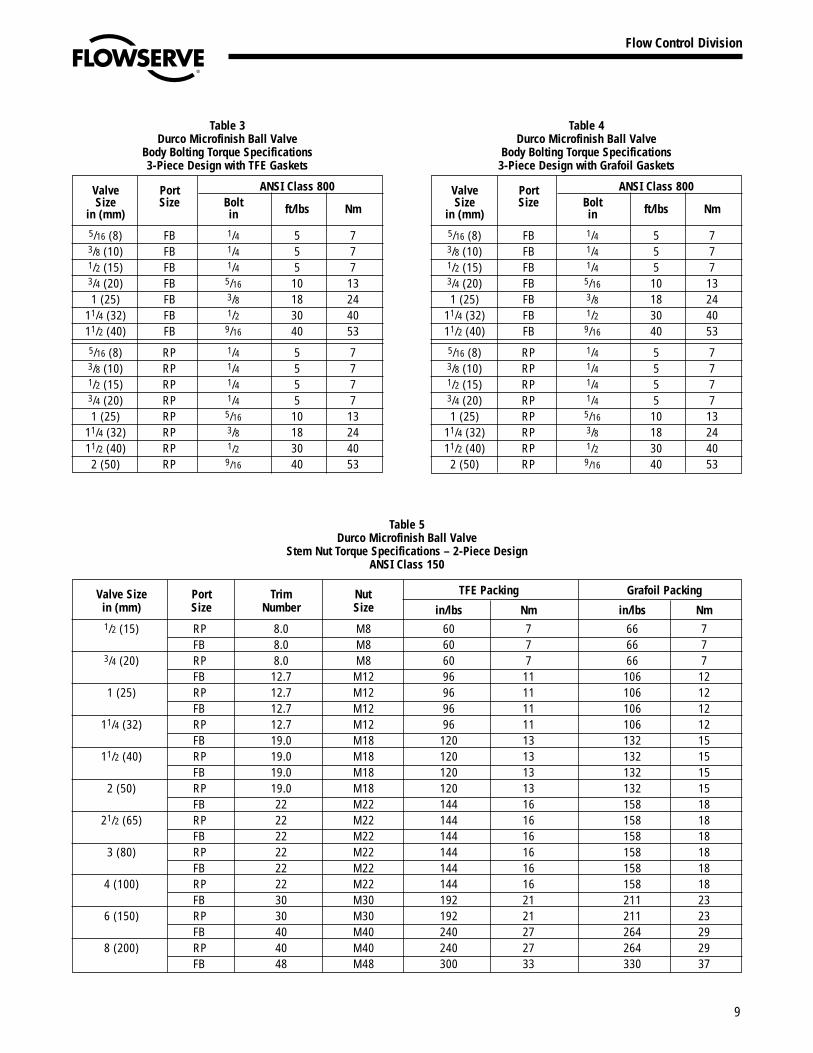
Table 3Durco Microfinish Ball Valve
Body Bolting Torque Specifications3-Piece Design with TFE Gaskets
Valve Port ANSI Class 800Size Size Bolt ft/lbs Nmin (mm) in
5/16 (8) FB 1/4 5 73/8 (10) FB 1/4 5 71/2 (15) FB 1/4 5 73/4 (20) FB 5/16 10 131 (25) FB 3/8 18 24
11/4 (32) FB 1/2 30 4011/2 (40) FB 9/16 40 535/16 (8) RP 1/4 5 73/8 (10) RP 1/4 5 71/2 (15) RP 1/4 5 73/4 (20) RP 1/4 5 71 (25) RP 5/16 10 13
11/4 (32) RP 3/8 18 2411/2 (40) RP 1/2 30 402 (50) RP 9/16 40 53
Table 4Durco Microfinish Ball Valve
Body Bolting Torque Specifications3-Piece Design with Grafoil Gaskets
Valve Port ANSI Class 800Size Size Bolt ft/lbs Nmin (mm) in
5/16 (8) FB 1/4 5 73/8 (10) FB 1/4 5 71/2 (15) FB 1/4 5 73/4 (20) FB 5/16 10 131 (25) FB 3/8 18 24
11/4 (32) FB 1/2 30 4011/2 (40) FB 9/16 40 535/16 (8) RP 1/4 5 73/8 (10) RP 1/4 5 71/2 (15) RP 1/4 5 73/4 (20) RP 1/4 5 71 (25) RP 5/16 10 13
11/4 (32) RP 3/8 18 2411/2 (40) RP 1/2 30 40
2 (50) RP 9/16 40 53
Table 5Durco Microfinish Ball Valve
Stem Nut Torque Specifications – 2-Piece DesignANSI Class 150
Valve Size Port Trim Nut TFE Packing Grafoil Packingin (mm) Size Number Size in/lbs Nm in/lbs Nm1/2 (15) RP 8.0 M8 60 7 66 7
FB 8.0 M8 60 7 66 73/4 (20) RP 8.0 M8 60 7 66 7
FB 12.7 M12 96 11 106 121 (25) RP 12.7 M12 96 11 106 12
FB 12.7 M12 96 11 106 1211/4 (32) RP 12.7 M12 96 11 106 12
FB 19.0 M18 120 13 132 1511/2 (40) RP 19.0 M18 120 13 132 15
FB 19.0 M18 120 13 132 152 (50) RP 19.0 M18 120 13 132 15
FB 22 M22 144 16 158 1821/2 (65) RP 22 M22 144 16 158 18
FB 22 M22 144 16 158 183 (80) RP 22 M22 144 16 158 18
FB 22 M22 144 16 158 184 (100) RP 22 M22 144 16 158 18
FB 30 M30 192 21 211 236 (150) RP 30 M30 192 21 211 23
FB 40 M40 240 27 264 298 (200) RP 40 M40 240 27 264 29
FB 48 M48 300 33 330 37

10
Flow Control Division
Section 1.0
Table 6Durco Microfinish Ball Valve
Stem Nut Torque Specifications – 2-Piece DesignANSI Class 300
Valve Size Port Trim Nut TFE Packing Grafoil Packingin (mm) Size Number Size in/lbs Nm in/lbs Nm
1/2 (15) RP 8.0 M8 60 7 66 7FB 8.0 M8 60 7 66 7
3/4 (20) RP 8.0 M8 60 7 66 7FB 12.7 M12 96 11 106 12
1 (25) RP 12.7 M12 96 11 106 12FB 12.7 M12 96 11 106 12
1-1/4 (32) RP 12.7 M12 96 11 106 12FB 19.0 M18 120 13 132 15
1-1/2 (40) RP 19.0 M18 120 13 132 15FB 19.0 M18 120 13 132 15
2 (50) RP 19.0 M18 120 13 132 15FB 22 M22 144 16 158 18
2-1/2 (65) RP 22 M22 144 16 158 18FB 30 M30 192 21 211 23
3 (80) RP 30 M30 192 21 211 23FB 30 M30 192 21 211 23
4 (100) RP 30 M30 192 21 211 23FB 40 M40 240 27 264 29
6 (150) RP 40 M40 240 27 264 29FB 48 M48 300 33 330 37
8 (200) RP 48 M48 300 33 330 37FB 60 M60 360 40 396 44
Table 7Durco Microfinish Ball Valve
Stem Nut Torque Specifications – 3-Piece DesignANSI Class 800
Valve Size Port Trim Nut TFE Packing Grafoil Packingin (mm) Size Number Size in/lbs Nm in/lbs Nm
1/2 (15) RP 8.0 M8 60 7 66 7FB 8.0 M8 60 7 66 7
3/4 (20) RP 8.0 M8 60 7 66 7FB 12.7 M12 96 11 106 12
1 (25) RP 12.7 M12 96 11 106 12FB 12.7 M12 96 11 106 12
1-1/4 (32) RP 12.7 M12 96 11 106 12FB 19.0 M18 120 13 132 15
1-1/2 (40) RP 19.0 M18 120 13 132 15FB 19.0 M18 120 13 132 15
2 (50) RP 19.0 M18 120 13 132 15

11
Flow Control Division
Section 1.0
MAINTENANCE SCHEDULE AND NOTES
Date Comments
Date Comments
Date Comments
Date Comments

Flow Control Division
Section 1.0
Or Consult Your Local Stocking Distributor
A T O M A C
Flowserve has the answer to your corrosion resistant, quarter-turn valving needs.
Printed in U.S.A.October 1999
© Flowserve Corporation
Clockwise from top right.
BTV-2000PTFE or UHMWPE linedchemical service valve
Atomac ® Lined ball valves• AKH2 full port• AKH2A ANSI dimensional• AKH2.2 DIN dimensional• AKH3 ANSI dimensional• AMP3 3-way• AKH5 ceramic lined• AKH6 tank drain• AKH7 (for glass pipe fitting)• ARV2 check valve• ASG sight glass• ARV/SG check valve/
sight glass• ASF strainer
Sleeveline ®
Non-lubricated, PTFE-sleeved plug valves• G4 Isolation• G4E – DIN Mounting Pad• G4 Marathon™• TSG4 Severe Service
T-Line ®
Non-lubricated, PTFE-lined plug valves• T-41
(ANSI Class 150)• T-43
(ANSI Class 300)
Big Max®
High performance valves• BX 2001 (ANSI Class 150)• MX (ANSI Class 300)
For more information, contact:
Flowserve CorporationFlow Control DivisionCookeville, Tennessee 38501(931) 432-4021
Flowserve Pte. Ltd.12 Tuas Avenue 20Republic of Singapore 63882465-862-3332
Flowserve Ahaus GmbHPostfach 1162D-48661 Ahaus, Germany49-2561-6860