inspection and maintenance manual for ... and maintenance manual for structural composites...
TRANSCRIPT

INSPECTION AND MAINTENANCE MANUAL FOR STRUCTURAL CO MPOSITES INDUSTRIES’ TYPE III CNG CYLINDERS
STRUCTURAL COMPOSITES INDUSTRIES 336 ENTERPRISE PLACE
POMONA, CA 91768 909 594-7777
Copyright © 2010 by Structural Composites Industries, LLC All Rights Reserved
1
Table of Contents Section Title Page 1.0 Definitions …………………………………………………………………… 2
1.1 Applicable Design, Certification, and Inspection Standards ……………… 4
2.0 Scope of This Manual ………………………………………………………… 4
3.0 Introduction ………………………………………………………………… 4
4.0 Manufacturer’s Cylinder Label ……………………………………………. 6
5.0 Filling Procedures For SCI Fuel Cylinders ……………………………… 6
6.0 Venting Procedures For SCI Fuel Cylinders ……………………………… 6
7.0 Cylinder Inspection …………………………………………………………. 6
7.1 External Inspection Procedures ……..……………………………………. 7
7.2 External Damage ………………………………………………. ……………. 7
7.3 Abrasion, Cut, and Impact Damage ……………………………………….. 8
7.3.a Abrasion, Cut, and Impact Damage Assessment for Type 3A cylinders ….. 10
7.3.b Abrasion, Cut, and Impact Damage Assessment for Type 3B cylinders ….. 11
7.4 Delaminations ………………………………………………………………… 11
7.5 Heat or Fire Damage ……………………………………………………. 12
7.6 Chemical Attack and Corrosion …………………………………………… 13
7.7 Unreadable Label …………………………………………………………. 13
7.8 Ultra Violet (UV) Damage …………………………………………………… 13
7.9 Fuel Leakage ……………..…………………………………………………... 14
8.0 Internal Inspection …………………………………………………………… 14
8.1 Internal Damage Assessment ……………………………………..…………. 15
8.2 Cylinder Ports, Valves, PRD’s, Adapters, O-rings …………………………. 15
8.2.a Cylinder Ports ……………………………….. … …………………………. 15
8.2.b Valves, PRD’s, Adapters, Installed Directly in Cylinder Ports …… ……. 15
8.2.c PRD’s Attached to Valves and Adapters ……………………………………. 15
8.2.d Cylinder O-ring and their specifications ……………..……………………. 16
9.0 Cylinder Repairs and Repair Procedure …………………………………… 16
10.0 Condemned Cylinders and Their Destruction ……………..……………. 16
11.0 Inspection Records …………………………………………………………… 17
Sample Inspection Record Sheet ……………………………………………… Appendix
2
1.0 Definitions Abrasion Damage: Damage to a container caused by wearing, grinding, or rubbing away of container material by friction. Burst Pressure: The minimum required pressure the container must withstand without bursting. Carbon Fiber: A type of reinforcement fiber. Multiple layers of resin impreganted carbon fibers are wrapped around the cylinder’s metal liner and serve as the primary stress bearing element within the cylinder structure. Carbon fiber is black in color, and composite made from carbon fiber has a semi-gloss black color. Condemned Cylinder: A cylinder that has been rendered unusable and incapable of holding pressure because it is no longer fit for service and cannot be repaired. Crazing: Hairline cracking of the resin, giving it an opaque or frost colored appearance. Cut Damage: Damage caused by a sharp object impacting with the composite surface. Delamination: A form of composite damage characterized by a fracture of the resin bond between adjacent strands of composite fiber or between composite fiber layers. Delaminations are typically caused by high energy collisions or impacts. Although cut or gouge damage is often present with delaminations, this may not be case if there is a high energy impact with a blunt or rounded object. Dome(s): The curved end portions of a CNG cylinder. External Coating: A surface treatment, typically a polyurethane based paint, that is applied for environmental protection and/or improved appearance. Fibers / Composite Fibers: Continuous fibrous strands wrapped around the cylinder liner to allow operation of the cylinder at its rated service pressure and transient filling pressures. Fiberglass: A type of reinforcement fiber. Normally used as a sacrificial outer layer on top of carbon composite to provide for additional protection and to facilitate inspection. When unpainted, fiberglass composite has a translucent whitish/green color. Filament Winding: The automated process of wrapping multiple layers of resin impregnated composite fibers around a cylinder liner to construct composite fuel tanks. Helix Fibers: A composite fiber layer wrapped lengthwise/longitudinally around the cylinder. Hoop Fibers: A composite fiber layer wrapped in a circular pattern around the circumference of the cylinder. Impact Damage: Damage caused by dropping or by a blow from another object. . Inspection Mark: A mark, label, or tag placed by an inspector on the container indicating acceptance of the container. The mark shall at least identify the inspecting agency and the date of inspection. Inspectionwrap: A sacrificial outer layer of fiberglass composite on a CNG cylinder. This layer is not required for certification of the cylinder, nor is it required to meet SCI’s cylinder performance requirements. As such, the inspectionwrap layer is sacrificial and the cylinder can be returned to service if this layer alone is cut, gouged, delaminated or abraded and there are no delaminations present. Level 1 Damage: Minor damage that has no adverse affect on the safety or use of a fuel container. This type of damage does not require repair (no appreciable depth or fraying of the composite fibers).

3
Level 2a Damage: Potentially repairable damage after consultation with SCI. Repairs can be made by SCI or the end user. End users must contact SCI to determine if the cylinder is repairable. . Level 2b Damage: Potentially repairable damage after consultation with SCI that is more severe than level 2a. Repairs can only be made by SCI, unless SCI determines that the repairs can be made by a qualified technician. Level 3 Damage: Severe Damage that cannot be repaired. Cylinders with Level 3 damage must be condemned and destroyed as described in section 10. Liner: The interior seamless aluminum enclosure that provides a gas tight enclosure and supports the exterior composite to help prevent composite damage during impact events. Manufacturer’s Label: The label(s) containing the official markings required by the applicable certification standard or regulations. Neck(s): The metal boss extending from the liner/cylinder and having internal threads for installation of a valve or pressure relief device. The necks on neck mountable cylinders are longer and have external threading to allow installation of neck mounting blocks thereon.. Neck Mounting Blocks: A pair of blocks for mounting the fuel containers to the vehicle. Each block has an internal bore for insertion of the cylinder necks therein. The first neck mounting block has a threaded bore for attachment directly onto to the external cylinder neck threads. This block is sometimes called a fixed mounting block because its position is fixed on the cylinder once it is threaded onto the cylinder neck and bolted to a mounting pedestal. The second block has a larger, unthreaded bore for insertion of a bushing attached to the opposite cylinder neck. The second mounting block is sometimes called a movable or floating block because the cylinder and bushing are free to axially move as the cylinder expands under pressure. Once installed on the cylinder necks, the neck mounting blocks are bolted onto the fuel module structure to form a lightweight method of attachment. Ports: Cylinder end openings for installation of valves or pressure relief devices therein. Pressure Relief Devices (PRD’s): A device installed on the cylinder or cylinder valve which releases the stored CNG if the cylinder is exposed to excessive heat. Rejected Container: A container that must be removed from service. Resin: The epoxy bonding agent that bonds adjacent composite fiber strands and adjacent composite layers into a high strength and resilient matrix. Scuff: Minor abrasion to the cylinder paint or surface. Service Pressure: The maximum permitted steady state operating pressure for the cylinder, as marked on the cylinder label. Stress Corrosion Cracking (SCC): Cracks in the composite material that are typically well defined and perpendicular to the fiber direction. They may appear as a family of cracks or a single crack. SCC is typically caused by exposure to harsh chemicals. Type 1 Container/Cylinder: A fuel container constructed entirely from metal. Type 2 Container/Cylinder: A fuel container having a metal liner with partial composite reinforcement. The metal liner is designed with sufficient strength to withstand 125% of service pressure and to carry the entire longitudinal stress load without composite reinforcement. The exterior composite reinforcement fibers are wound only in the hoop/circumferential direction around the cylinder sidewall.

4
Type 3 Container/Cylinder: A fuel container having a metal liner that carries some of the pressure stresses but does not have sufficient strength by itself to hold full service pressure without composite reinforcement. These cylinders have a full composite exterior with fibers applied in both hoop/circumferential and helical/axial directions. Type 3A Container/Cylinder: A type 3 cylinder where the exterior composite reinforcement is entirely carbon composite. Type 3B Container/Cylinder: A type 3 cylinder where the exterior composite reinforcement comprises an inner carbon fiber composite matrix and outer, sacrificial layers of sacrificial fiberglass composite. 1.1 Applicable Design, Certification, and Inspection Standards: Federal Motor Vehicle Safety Standard (FMVSS) 304 (Code of Federal Regulations Title 49, Section 571.304) Compressed Gas Association Pamphlet CGA C-6.4, Methods for External Visual Inspection of Natural Gas Vehicle (NGV) Fuel Containers and Their Installations. NOTE: THE INFROMATION IN THIS MANUAL PREVAILS WHEN THERE IS A CONFLICT WITH CGA 6.4 GUIDELINES. 2.0 Scope of this Manual This manual covers Structural Composites Industries CNG cylinder models. This manual cannot be used for the inspection and maintenance of CNG fuel cylinders manufactured by other companies, nor for SCI cylinder models used in non-CNG vehicle applications. 3.0 Introduction Structural Composites Industries (SCI) and its predecessor company Aerojet General developed Type III composite pressure vessels in the 1950s for rockets and other aerospace applications. Later, Type III vessels became a preferred choice for natural gas and hydrogen powered vehicles due to their gas tight structure, low relative weight, and superior durability. Type III vessels (often called cylinders, tanks, or fuel containers) have a seamless and gas tight aluminum liner reinforced by an exterior composite matrix. The entire metal liner, excluding the neck ends, is wrapped with multiple layers of resin impregnated composite fiber in a continuous filament winding process. Prior to the early 1990’s, CNG cylinders were principally made with fiberglass composite. When unpainted, fiberglass composite has a translucent white/green color. Carbon fiber became available in the 1990’s and this material is now preferred due to its greater tensile strength and its ability to carry greater pressure related stresses. When unpainted, carbon fiber is black. A sectioned Type 3 cylinder and a ring segment cut from the body of a type 3 cylinder are shown below.

5
The composite fiber layers on CNG cylinders are wrapped in either a circumferential (hoop) orientation around the liner body or in a longitudinal (helical) orientation spanning the entire cylinder length including over the dome ends. The fibers and resin are then cured at elevated temperature to form a high strength composite matrix. Once cured, the composite matrix becomes the primary pressure retaining element in the cylinder structure. However, typical composite materials are not gas tight and they can internally fracture if they should flex too much during an impact event. For these reasons, the internal metal liner functions to provide a gas tight enclosure and to protect the composite from internal fractures by preventing or greatly minimizing deflection and breakage of the composite matrix during impact events.
Since the early 1990’s, SCI has manufactured two CNG cylinder types: Type 3A and 3B. Type 3A cylinders have a composite matrix made entirely from resin impregnated carbon fiber, and in this case extra carbon fiber layer(s) are applied to allow for some damage tolerance. Type 3A are generally lighter in weight than Type B cylinders and are shown at left in Figure 1 below. Type 3B cylinders have a carbon composite matrix and an outer layer of sacrificial fiberglass composite over of the carbon composite as shown at right in Figure 1. Type 3B cylinders are designed, tested, and certified for use without the fiberglass. As such, the fiberglass composite is sacrificial in nature when it is added to the cylinder structure. Consequently, damage to the fiberglass layer alone is considered superficial and not structurally important so long as there are no internal delamination bruises present. Delamination bruises and other forms of cylinder damage and shown and described in the sections that follow.
Figure 1: Carbon Composite (Type 3A - left) and Carbon/Fiberglass Composite (Type 3B - right) Cylinders
All CNG fuel tanks manufactured for use in the United States must be designed and certified in accordance with Federal Motor Vehicle Safety Regulation 304 (FMVSS 304, Code of Federal Regulations Title 49, Section 571.304). End users should be familiar with this regulation and they must check to see if any state or local regulations also govern the use of CNG fuel tanks in their jurisdiction.
Fiberglass Composite Carbon Composite

6
4.0 Manufacturer’s Cylinder Label CNG fuel tanks are marked in compliance with FMVSS 304 (subsection 7.4). The label is wrapped around the cylinder's circumference and contains the following information:
a). Service pressure (Typically 3600 psig at 70° F for North American vehicles). b). Cylinder serial number c). SCI Part Number and Model Number d). Test date (MM/YY) e). Service temperature range f). FMVSS 304 certification marking with verification stamp by an independent inspector g). Cylinder inspection frequency information h). CNG Only statement i). Expiration date j). SCI Contact information k). The statement “For use only with the manufacturer's approved pressure relief devices and valves” 5.0 Filling Procedures for SCI CNG Cylinders There are no filling restrictions in hot or cold weather, and there are no requirements for pre-heating the cylinders or pre-conditioning the gas. When slow filling (filling operations greater than 1 hour duration), the tank must be filled to the rated service pressure indicated on the container label. For fast filling procedures of shorter duration, the fast fill pressure can be up to 125% of the rated service pressure to obtain the rated service pressure corrected to 70F once the gas cools and settles. 6.0 Venting Procedures for SCI Fuel Cylinders Cylinders may be depressurized or vented only by qualified technicians. The technician is responsible to ensure the cylinders are handled safely, that all procedures are followed, and that all local, state, and Federal fire and environmental codes are known and followed prior to venting. The technician(s) must also refer to the vehicle manufacturer's instructions regarding the discharge of CNG from the fuel system.
7.0 Cylinder Inspection CNG fuel tanks must be inspected for damage at the following intervals: (1) Upon installation on the vehicle (2) Every 36 months or 36,000 miles of service, whichever comes first. (3) After any incident which potentially damaged the cylinders (such as impacts, collisions, fire, accident, exposure to corrosive agents, or similar events) (4) When there is any unusual fuel system behavior (popping or cracking noises during filling, natural gas odors, hissing, unexpected pressure drops) (5) As may be required under any state, provincial, or local regulations Inspection of SCI CNG cylinders shall be performed in accordance with this document and the Compressed Gas Association (CGA) pamphlet C6.4 "Methods for External Visual Inspection of Natural Gas Vehicle (NGV) Fuel Containers and Their Installations".
The inspector must also determine if there is any unusual service history since the last inspection. For example, vehicle accidents, or exposure to corrosive acids. Also, for cylinders mounted on the vehicle undercarriage, whether the vehicle

7
underside received impact damage such as from roadside debris or from “bottoming out” when passing over speed bumps or curbs. Any such unusual service history should be noted in the vehicle and fuel system service records.
7.1 External Inspection Procedures Inspectors must have a clear and unobstructed view of the entire cylinder exterior surface. Dirt or grit must be cleaned / removed if it prevents persons from observing possible damage to the cylinder exterior surface. Light dusting on the cylinder can remain and in fact is sometimes useful by providing a witness mark for any impacts, provided that the dusting does not have a corrosive influence and it does not prevent persons from reading the cylinder label or seeing possible cylinder damage. To gain an unobstructed view of the entire cylinder, users may have to remove protective covers, sleeves, guards, etc that may be installed around the cylinders. Inspectors may also need inspection/dental mirrors, boroscopes, and/or small high intensity lamps for viewing inaccessible areas. If the entire cylinder cannot be viewed, then it must be removed from the vehicle for inspection.
Important!: Inspectors must check the expiration date on the cylinder label. Make sure that the cylinder(s) are not in use beyond their expiration date. Expired cylinders must be removed from service and rendered incapable of holding pressure as outlined in section 10.0.
Caution: Never remove or otherwise disconnect a cylinder that contains pressure! Be certain the cylinder is completely vented before removal. Caution: Do not use paint removers, solvents, acids or harsh chemicals to clean cylinders. These can degrade and weaken the composite. Use water and/or a mild household detergent for cleaning the cylinder exterior.
7.2 External Damage Type 3 cylinders are recognized as an extremely robust and resilient design. However, any fuel tank can be damaged in service and end users must periodically inspect their tanks for possible damage. This section is intended to help end users identify and inspect for various types of damage, which can be defined as the following types:
� Abrasion, cut/gouge damage � Impact Delaminations � Heat or fire damage � Leaking � Chemical attack � Ultra Violet (UV) Damage � Label Damage or Unreadable label

8
7.3 Abrasion, Cut, and Impact Damage Abrasion damage is caused by an object rubbing against the cylinder and can appear as scuff marks and/or fraying of the fibers on the outer composite surface as shown in Figure 2 below.
Figure 2: Abrasion Damage (Cylinder Type 3B left. Type 3A right)
Cut and gouge damage will appear as a break in the composite surface as shown in Figure 3 below. Cut, gouge, and abrasion damage is evaluated using the methods described in section 7.3.a (for Type 3A cylinders) or 7.3.b (for Type 3B cylinders).
Figure 3: Cut and Gouge Damage (Cylinder type 3B top, 3A bottom)

9
7.3.a Abrasion, cut, and gouge damage assessment for TYPE 3A cylinders Abrasion, cut, and impact damage on Type 3A cylinders is assessed using Figures 4 and Table 5 below. First, measure the damage depth, width, and length. Also inspect for delaminations as explained in section 7.4 below. Second, determine the damage location zone as indicated in Figure 4 below. Zone A extends 1 inch from the outer face of the cylinder neck as measured along the cylinder dome contour. Zone B extends 2 inches beyond Zone A. Zone C extends from Zone B to the shoulder of the cylinder dome end. Zone D is the cylinder sidewall region.
Figure 4: Cylinder Damage Location Zones for Type 3A Cylinders
Next, refer to Table 5 and compare the measured damage depth with the limits for the applicable cylinder ZONE:
Table 5: Damage Limits for Type 3A Cylinders
Damage Level 1: Minor damage. The cylinder can be returned to service without repair ** Contact SCI if Level 1 damage length exceeds 8 inches regardless of the damage level. ** Contact SCI if Level 1 cut or gouge width exceeds 1/8 inches regardless of the damage level
Damage Level 2a: Potentially repairable damage after consultation with SCI. Repairs can be made by the end user.
Damage Level 2b: Potentially repairable damage after consultation with SCI. Repairs are generally repairable by SCI unless the nature of the damage allows end user repair.
Damage Level 3: Severe, unrepairable damage. The cylinder must be condemned and rendered incapable of holding pressure (see section 10.0 below).
10
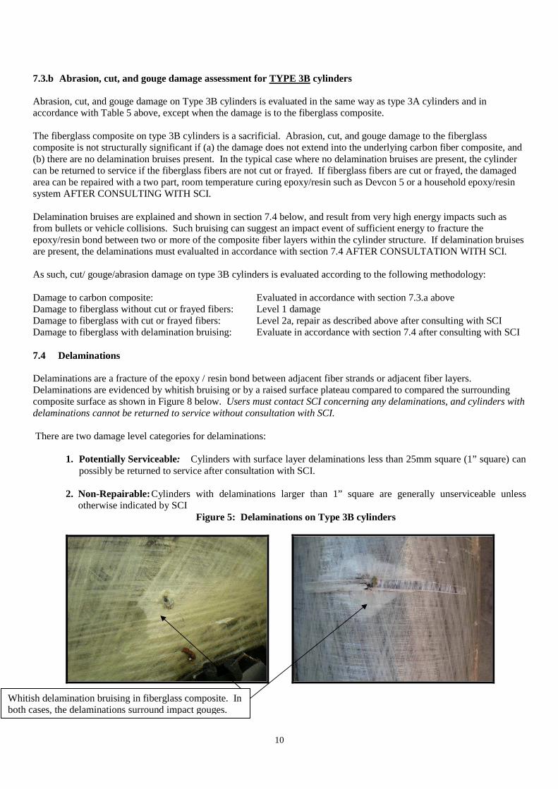
7.3.b Abrasion, cut, and gouge damage assessment for TYPE 3B cylinders Abrasion, cut, and gouge damage on Type 3B cylinders is evaluated in the same way as type 3A cylinders and in accordance with Table 5 above, except when the damage is to the fiberglass composite. The fiberglass composite on type 3B cylinders is a sacrificial. Abrasion, cut, and gouge damage to the fiberglass composite is not structurally significant if (a) the damage does not extend into the underlying carbon fiber composite, and (b) there are no delamination bruises present. In the typical case where no delamination bruises are present, the cylinder can be returned to service if the fiberglass fibers are not cut or frayed. If fiberglass fibers are cut or frayed, the damaged area can be repaired with a two part, room temperature curing epoxy/resin such as Devcon 5 or a household epoxy/resin system AFTER CONSULTING WITH SCI. Delamination bruises are explained and shown in section 7.4 below, and result from very high energy impacts such as from bullets or vehicle collisions. Such bruising can suggest an impact event of sufficient energy to fracture the epoxy/resin bond between two or more of the composite fiber layers within the cylinder structure. If delamination bruises are present, the delaminations must evalualted in accordance with section 7.4 AFTER CONSULTATION WITH SCI. As such, cut/ gouge/abrasion damage on type 3B cylinders is evaluated according to the following methodology: Damage to carbon composite: Evaluated in accordance with section 7.3.a above Damage to fiberglass without cut or frayed fibers: Level 1 damage Damage to fiberglass with cut or frayed fibers: Level 2a, repair as described above after consulting with SCI Damage to fiberglass with delamination bruising: Evaluate in accordance with section 7.4 after consulting with SCI 7.4 Delaminations Delaminations are a fracture of the epoxy / resin bond between adjacent fiber strands or adjacent fiber layers. Delaminations are evidenced by whitish bruising or by a raised surface plateau compared to compared the surrounding composite surface as shown in Figure 8 below. Users must contact SCI concerning any delaminations, and cylinders with delaminations cannot be returned to service without consultation with SCI. There are two damage level categories for delaminations:
1. Potentially Serviceable: Cylinders with surface layer delaminations less than 25mm square (1” square) can
possibly be returned to service after consultation with SCI. 2. Non-Repairable: Cylinders with delaminations larger than 1” square are generally unserviceable unless
otherwise indicated by SCI Figure 5: Delaminations on Type 3B cylinders
Whitish delamination bruising in fiberglass composite. In
both cases, the delaminations surround impact gouges.

11
7.5 Heat or Fire Damage
Heat or fire damage is evidenced by discoloration (browning), charring, burning, or melting of the cylinder or its labels as shown in Figure 9 below. Cylinders must be inspected after any vehicle fire or when a CNG vehiclewas very near a fire such that the onbard cylinders were exposed to extreme heat. Persons must also inspect pressure relief devices for evidence of exposure to heat (e.g. activation). The two categories of heat damage are as follows:
1. Allowable: The cylinder surface is merely soiled from smoke or soot blown from a distant heat source. There must be no signs of charring, burning, or melting of the composite, and no evidence of pressure relief device (PRD) activation. 2. Unacceptable: Any charring, burning, or melting on the cylinder surface or any prd activation. Cylinders with Unacceptable damage must be condemned.

12
Figure 9: Unacceptable Heat Damage (Type 3A left, Type 3B right)
7.6 Chemical Attack Chemical attack can appear as deterioration of the composite fibers and/or resin such as tackiness on the cylinder surface or composite melt zones that resolidified. Corrosion might also manifest itself as cracking or discoloration of composite reinforcement. Any evidence of chemical attack is unacceptable and the cylinder must be removed from service and rendered unusable as described in section 10.0. 7.7 Unreadable Label Contact SCI if any of the required markings listed in section 4.0 are not readable. In most cases, the label can be replaced using the serial markings stamped into the cylinder neck. Important!: Do not place a cylinder into service that has an unreadable label. 7.8 Ultraviolet (UV) Damage Most types of epoxy resin will react to UV radiation after extended exposure. As shown in Figure 10 below, UV damage is evidenced by an opaque white staining or haze that develops on the outer composite surface layers. INSPECTORS MUST CONTACT SCI CONCERNING ANY UV DAMAGE. Over time, continuous UV exposure can in some circumstances progressively degrade composite laminates. If caught early, the affected areas can be painted with a gloss or semi-gloss black paint conforming with Federal Specification 595-17038. Sherwin Williams, Cardinal, and other companies supply this type of paint.
Figure 10: UV Damage On Fiberglass and Carbon Composite
UV damage

13
7.9 Fuel Leakage Type III cylinders have a gas tight liner, and any leakage through the liner is not an acceptable condition. Suspected tank leaks must be inspected. If the cylinder is already pressurized prior to the inspection, vent in accordance with local regulations and the vehicle manufacturer’s guidelines as explained in section 6.0 above, then proceed with the steps outlined below.
� Slowly fill the tank to 500 psig � Mix a 5% soap and water solution � Brush the solution onto all equipment connected to the cylinder (valves, pressure relief devices,
interconnecting tubes, fittings) � Check for bubbles � Mark connection or leaking component � Depressurize the cylinder according to the CNG fuel system manufacturer's procedure.
Leaking cylinders must be removed from service and rendered unusable as described in section 10.0. 8.0 Internal Cylinder Inspections At the time of this manual publication, SCI is not aware of any regulations within the United States, Canada, Europe, or Japan which mandate periodic internal inspections for CNG motor vehicle fuel storage cylinders. Even so, end users must investigate whether local regulations impose such obligations and also to stay informed of any Federal, State/Provincial, or local regulatory changes which mandate internal cylinder inspections. In the absence of regulations, internal cylinder inspections are only required when there is cause to believe the cylinder sustained internal damage, such as if a corrosive substance is allowed in the vehicle fuel storage system. Compressor oil carryover from fill stations is generally not problematic for SCI type 3 cylinders unless the compressor oil was contaminated with a corrosive agent. If internal inspections are necessary, users can follow the following general guidelines: 1. Make sure the fuel system is vented/depressurized prior to the inspection, in accordance with the vehicle manufacturer’s de-fueling procedure. 2. Once the system is defueled/depressurized, disconnect the tank from all fuel system tubing, the tank valve, and the opposite end PRD or end plug (if any). Please refer to section 8.2 for removal of valves, pressure relief devices, and/or adapters from the tank ports. 3. Remove any loose foreign matter and drain any fluids that may be present in the tank.
Note: If cleaning is necessary, users should first try high pressure air and then acetone, rubbing alcohol, or high pressure water with or without a mild soap if necessary. However all residual moisture / water must be completely removed after the inspection in order to prevent future corrosion. To remove residual moisture, the cylinder must be fully purged with high pressure air, rubbing alcohol or acetone.
Important : Alkaline solutions, such as caustic soda should not be used due to potential corrosion.
4. Each cylinder should be inspected with an inspection lamp of sufficient intensity to identify any damage such as corrosion, dents or cracks. Fiber optic inspection lights are best for this type of inspection. 5. Inspect the seal and engagement surfaces on the tank ports and any attached valves, pressure relief devices, and adapters in accordance with section 8.2 below to make sure they have full form and are free from burrs, scratches, gouges or other imperfections which might prevent effective engagement and pressure seal. 6. Re-install the valve and pressure relief devices into the tank ports in accordance with section 8.2 below.
14
8.1 Internal Damage Assessment
Any cylinder with internal dents or cracks must be condemned. If any corrosion pitting is observed, contact Structural Composites Industries before placing the cylinder back in service.
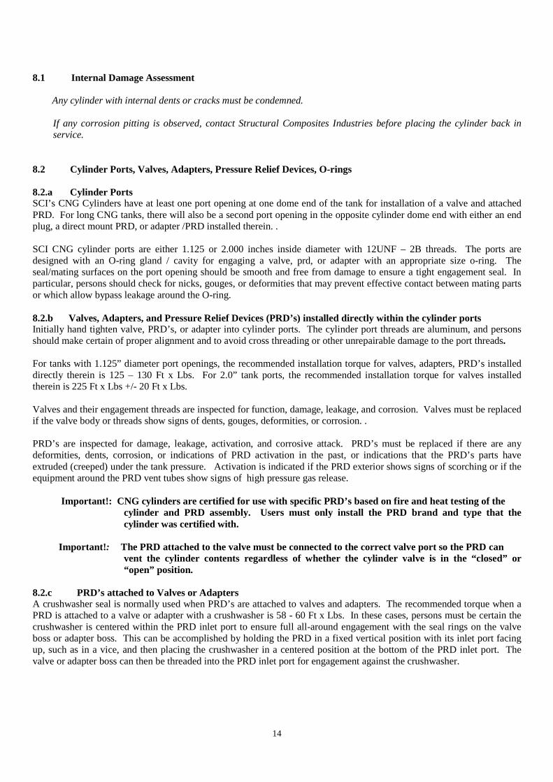
8.2 Cylinder Ports, Valves, Adapters, Pressure Relief Devices, O-rings 8.2.a Cylinder Ports SCI’s CNG Cylinders have at least one port opening at one dome end of the tank for installation of a valve and attached PRD. For long CNG tanks, there will also be a second port opening in the opposite cylinder dome end with either an end plug, a direct mount PRD, or adapter /PRD installed therein. . SCI CNG cylinder ports are either 1.125 or 2.000 inches inside diameter with 12UNF – 2B threads. The ports are designed with an O-ring gland / cavity for engaging a valve, prd, or adapter with an appropriate size o-ring. The seal/mating surfaces on the port opening should be smooth and free from damage to ensure a tight engagement seal. In particular, persons should check for nicks, gouges, or deformities that may prevent effective contact between mating parts or which allow bypass leakage around the O-ring. 8.2.b Valves, Adapters, and Pressure Relief Devices (PRD’s) installed directly within the cylinder ports Initially hand tighten valve, PRD’s, or adapter into cylinder ports. The cylinder port threads are aluminum, and persons should make certain of proper alignment and to avoid cross threading or other unrepairable damage to the port threads. For tanks with 1.125” diameter port openings, the recommended installation torque for valves, adapters, PRD’s installed directly therein is 125 – 130 Ft x Lbs. For 2.0” tank ports, the recommended installation torque for valves installed therein is 225 Ft x Lbs +/- 20 Ft x Lbs. Valves and their engagement threads are inspected for function, damage, leakage, and corrosion. Valves must be replaced if the valve body or threads show signs of dents, gouges, deformities, or corrosion. . PRD’s are inspected for damage, leakage, activation, and corrosive attack. PRD’s must be replaced if there are any deformities, dents, corrosion, or indications of PRD activation in the past, or indications that the PRD’s parts have extruded (creeped) under the tank pressure. Activation is indicated if the PRD exterior shows signs of scorching or if the equipment around the PRD vent tubes show signs of high pressure gas release.
Important!: CNG cylinders are certified for use with specific PRD’s based on fire and heat testing of the
cylinder and PRD assembly. Users must only install the PRD brand and type that the cylinder was certified with.
Important! : The PRD attached to the valve must be connected to the correct valve port so the PRD can
vent the cylinder contents regardless of whether the cylinder valve is in the “closed” or “open” position.
8.2.c PRD’s attached to Valves or Adapters A crushwasher seal is normally used when PRD’s are attached to valves and adapters. The recommended torque when a PRD is attached to a valve or adapter with a crushwasher is 58 - 60 Ft x Lbs. In these cases, persons must be certain the crushwasher is centered within the PRD inlet port to ensure full all-around engagement with the seal rings on the valve boss or adapter boss. This can be accomplished by holding the PRD in a fixed vertical position with its inlet port facing up, such as in a vice, and then placing the crushwasher in a centered position at the bottom of the PRD inlet port. The valve or adapter boss can then be threaded into the PRD inlet port for engagement against the crushwasher.

15
Note: A new crushwasher should be installed during replacement of a PRD or valve, even if the original crushwasher appears to be in good condition. The original crushwasher will have some deformation and imprinting after its original installation, and it cannot be relied upon to make an effective seal once it is so deformed.
8.2.d Cylinder O-Rings For 1.125” ports, O-rings on valves or PRD’s should be Parker NBR Nitrile N756-75, 1.109 inch inside diameter x .139 inch thick. For 2” ports, the O-ring should be Parker NBR Nitrile N304-75, 1.984 inch inside diameter x .139 inch thick. Equivalent O-rings of the same material are acceptable if they have the same dimensions and hardness/durometer. O-rings have a finite serive life and it is recommended to install new O-rings when re-installing a valve, adapter, or PRD into a tank port, even if the original O-ring appears to be in good condition. When installing a new O-ring, it is recommended to lightly lubricate it with a compatible lube so the O-ring won’t be cut or torn when it is pulled across threads. 9.0 Cylinder Repair Procedure SCI must be contacted before any repairs are made to CNG cylinders. In addition, repairs can only be carried out by persons approved by SCI or persons with sufficient CNG cylinder experience as specified under CGA Pamphlet C6.4. (1) Position cylinders for full access to the damaged area (2) Clean the damaged area using compressed air or a clean cloth
Re-inspect the damaged area to insure that the damage depth does not exceed allowable limits (3) Cut away any loose fibers (4) Lightly abrade the damaged area using 320 (or finer) grit sandpaper or equivalent (5) Mix epoxy resin sufficient to cover the damaged area per the resin manufacturer's instructions
A two part epoxy resin system with room temperature curing must be used (such as Devcon 5 epoxy resin having a 5 minute curing period at room temperature with full bonding strength in approximately 1 hour ).
(6) Apply resin to the damaged area using a brush. Brush all fibers down smooth. (7) Allow the epoxy resin to cure per the epoxy resin manufacturer’s recommendations
10.0 Condemned Cylinders and Their Destruction Condemned Cylinders must be rendered incapable of holding pressure and then disposed of in accordance with the following procedure:
� Purge the cylinder using an inert gas or by filling with water.
Caution: Without purging, cylinders with open ports may still contain enough residual natural gas to cause an explosive hazard.
� Drill two 1/2" (12.5mm) or larger holes through the cylinder sidewall, saw off a neck end, or cut a similar opening through the vessel structure so it cannot be pressurized
� Dispose of the cylinder in accordance with local regulations.
Urgent: There is an industry wide problem with the re-sale of expired, condemned, and damaged CNG cylinders in secondary markets such as on EBay. Persons must ensure that disposed cylinders are no longer functional in the event that a re-seller gains possession of the cylinders. Note: As of this writing, SCI is not aware of any restrictions on the disposal of our cylinders’ raw material constituents (aluminum, carbon fiber, and cured epoxy/resin materials that are in an inert condition). Some local recyclers may pay for the aluminum (high purity 6061 alloy) or at least pick up the non-functional vessels at no cost.

16
11.0 Inspection Records Cylinder inspectors must keep accurate records of each cylinder inspected. A sample inspection record is provided in the Appendix. CGA Pamphlet C6.4, Appendix A also contains a sample inspection sheet.

APPENDIX
Sample Inspection Record Date:
Cylinder Part Number (P/N)
Cylinder Serial Number
Cylinder Date of
Manufacture
External Condition Acceptable
Y/N
Internal Inspection Required
Y/N
Internal Condition Acceptable
Y/NRepair Y/N PASS/FAIL AND REMARKS