enhanced composites integrity through structural … composites integrity through structural health...
TRANSCRIPT
Enhanced Composites Integrity Through StructuralHealth Monitoring
Victor Giurgiutiu & Constantinos Soutis
Received: 19 December 2011 /Accepted: 22 December 2011# Springer Science+Business Media B.V. 2012
Abstract This paper discusses the topic of how the integrity of safety-critical structuralcomposites can be enhanced by the use of structural health monitoring (SHM) techniques.The paper starts with a presentation of how the certification of flight-critical compositestructures can be achieved within the framework of civil aviation safety authority require-ments. Typical composites damage mechanisms, which make this process substantiallydifferent from that for metallic materials are discussed. The opportunities presented by theuse of SHM techniques in future civil aircraft developments are explained. The paper thenfocuses on active SHM with piezoelectric wafer active sensors (PWAS). After reviewing thePWAS-based SHM options, the paper follows with a discussion of the specifics of guidedwave propagation in composites and PWAS-tuning effects. The paper presents a number ofexperimental results for damage detection in simple flat unidirectional and quasi-isotropiccomposite specimens. Calibrated through holes of increasing diameter and impact damage ofvarious energies and velocities are considered. The paper ends with conclusions andsuggestions for further work.
Keywords Composites . Composite structures . Structural integrity . Structural healthmonitoring . Piezoelectric wafer active sensors . SHM . NDE . PWAS
1 Introduction
In order for composite materials to be used more extensively in load carrying aircraftstructures, they have to be maintained in a safe and economical manner. Critical defects/cracks may be induced in the structure requiring repair before the next scheduled inspection.Continuous monitoring will significantly increase operational safety. The information
Appl Compos MaterDOI 10.1007/s10443-011-9247-2
V. Giurgiutiu (*)University of South Carolina, Columbia, SC, USAe-mail: [email protected]
C. SoutisUniversity of Sheffield, Sheffield, South Yorkshire, UK
acquired in real-time would also benefit the understanding on fracture mechanics of com-posites, improving the confidence in their use and broadening their applications. Currentlythe cost of primary components inspection can be as high as one third of acquiring andoperating these composite structures [1–3]. In order to compete in the increasingly demand-ing area of aircraft structures cost effective techniques need to be developed. Large areasneed to be scanned rapidly without removal of individual components, minimizing thedisruption of the structure’s operation.
Large structures such as the Boeing 787 Dreamliner and Airbus A350 XWB (extra widebody) are now at various stages in the design/manufacture/certification/delivery cycle. Oneof the most difficult problems to be overcome during the certification process of such aircraftby the civil aviation authorities for safe commercial use is to guarantee the structuralintegrity of large composite structures over the 30 years life of the aircraft. This is atechnological new ground for large integral composite structures, with wing lengths of morethan 25 m, fuselage barrel lengths of 50 m and diameter 5 m [4].
A critical safety issue for the design of primary aircraft structures is vulnerability anddamage tolerance due to mechanical loading such as foreign object impacts from bird strike,hail, tire rubber and metal fragments [5, 6]. New composite aircraft structures are vulnerableto impact damage, due to the relatively thin composite skins and the generally brittlebehavior of carbon fiber reinforced epoxy resins. This aspect of structural integrity is amajor problem for the industry as it seeks a viable strategy for design and certification oflarge composite aircraft structures subjected to impact damage, particularly with respect tothe known composite problems of Non-Visible Damage / Barely Visible Impact Damage(NVD/BVID).
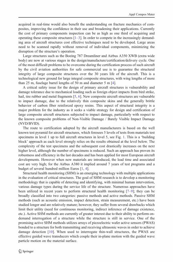
The route to certification adopted by the aircraft manufacturers is based on the wellknown test pyramid for aircraft structures, which foresees 5 levels of tests from materials testspecimens in level 1 up to full aircraft structures in level 5, see Fig. 1. This is a ‘buildingblock’ approach as each level strongly relies on the results obtained at the level below. Thecomplexity of the test specimens and the subsequent cost drastically increases on the nexthigher level, although the number of specimens is reduced. Such an approach has proven itsrobustness and efficiency in the last decades and has been applied for most European aircraftdevelopments. However when new materials are introduced, the lead time and associatedcost are very high; for the Airbus A380 it implied around 7 years of test programs and abudget of several hundred million Euros [1, 4].
Structural health monitoring (SHM) is an emerging technology with multiple applicationsin the evaluation of critical structures. The goal of SHM research is to develop a monitoringmethodology that is capable of detecting and identifying, with minimal human intervention,various damage types during the service life of the structure. Numerous approaches havebeen utilized in recent years to perform structural health monitoring [7–9]; they can bebroadly classified into two categories: passive methods and active methods. Passive SHMmethods (such as acoustic emission, impact detection, strain measurement, etc.) have beenstudied longer and are relatively mature; however, they suffer from several drawbacks whichlimit their utility (need for continuous monitoring, indirect inference of damage existence,etc.). Active SHM methods are currently of greater interest due to their ability to perform on-demand interrogation of a structure while the structure is still in service. One of thepromising active SHM methods utilizes arrays of piezoelectric wafer active sensors (PWAS)bonded to a structure for both transmitting and receiving ultrasonic waves in order to achievedamage detection [10]. When used to interrogate thin-wall structures, the PWAS areeffective guided wave transducers which couple their in-plane motion with the guided waveparticle motion on the material surface.
Appl Compos Mater
The aircraft requirements do not prescribe a rigid test methodology. Compliance to therequirements may be demonstrated either by means of testing or analysis. It is here where thecomposites scientists and engineers are required to support the aircraft designers. Withimproved understanding of composites damage mechanisms, effect of fabrication processingparameters, improved test methodologies, new non-destructive evaluation (NDE) and struc-tural health monitoring (SHM) technologies, and the ability to describe these effects inanalytical and numerical (Finite Element) models, analytically based justifications cancontribute to reduce large test programs. Thus a central theme for the research communityis to develop and validate computational tools to support the design of an optimizedcomposite aircraft under the full range of flight and service loads. The introduction of‘virtual testing’ and hence ‘certification by analysis’ with a scientific basis at the compositesmicro-scale implies a cultural change in the way of working of the airframe community. Itwill have a clear positive impact on development cost and lead time, which is especiallyimportant for the introduction of composite materials into large aircraft structures. Thesimulation-based designs will significantly speed-up the decision path by allowing earlierdecisions at each level of the test pyramid, and will reduce the development and testing ateach level. A smaller number of physical tests will remain to validate the simulation baseddecisions.
Thus the societal need is clear in the case of the aircraft industry where scientificdevelopments at the composites micro-scale level, which improve our understanding ofstructural integrity, will lead to optimized structures and validated computational tools fordirect application by the industry in future aircraft developments. The same issues apply of
Fig. 1 The test pyramid for civil aircraft composite structures (a building block approach based on certifi-cation requirements)
Appl Compos Mater
course to other industries, for example in the development of large composite hulls on navalships and fast patrol boats, or 60 meters composite wind rotor blades for renewable energygeneration. In all cases a coordinated effort is urgently needed between the academiccommunity, which tends to concentrate on composites analysis at the micro and macro-scales and the applications engineers in the aircraft, marine, transport and energy industries.
The aim of this paper is to demonstrate how active SHM techniques, especially thosebased on Lamb waves generated by piezoelectric wafer active sensors (PWAS) can be usedto continuously monitor mechanical induced damage in composite structures, typical to thatexperienced by aircraft components and to assess their structural integrity.
2 Damage Mechanisms and Damage Accumulation in Composite Structures
Fatigue life prediction for composite materials has generally not been a major issue in thedesign of composite structures, due to the low levels of ultimate design strain used currently[4]. However, if composite materials are to be used to their full potential, design strain levelswill have to rise and damage growth in fatigue will then become a serious design consid-eration. To develop improved life predicting methodologies that would result in moreweight- and cost-effective composite structures, the understanding of fatigue failure processin composites needs to be broadened and links between observable damage/failure mecha-nisms and fatigue life need to be established.
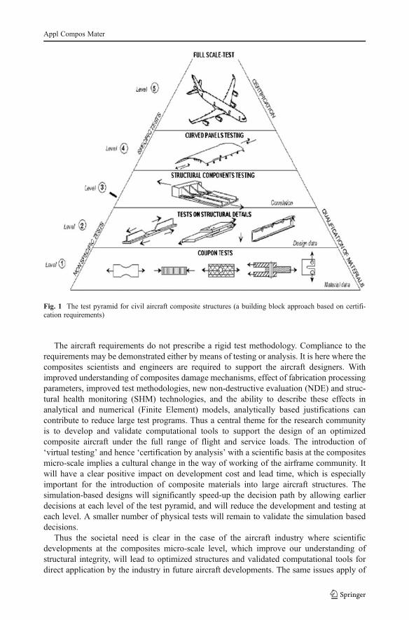
Fatigue behavior of composite laminates is characterized by sequential accumulation ofdamage in the form of matrix cracking, local and edge delamination, fiber/matrix debondingand fiber breakage [11, 12]. Figure 2 shows a schematic drawing of a composite with suchdamage; the upper drawing showing a plan view and the lower schematic showing an edgeview. The upper drawing shows (i) a longitudinal split (a type of matrix cracking damage inwhich the cracks run parallel to the fibers in the loading direction), (ii) matrix cracks runningparallel to fibers in plies oriented at 900 to the loading direction (transverse ply cracks), and(iii) two types of ply delamination—one associated with matrix cracking but initiated from afree edge, i.e., edge delamination with the second type being local delaminations associatedwith longitudinal splits or matrix cracks. The lower drawing shows the edge view of thisdamage and the inset in Fig. 2 shows a fourth type of damage: fiber breakage and associatedfiber/matrix debonding (interface failure). All of these types of damage lead to a permanentdegradation of the laminate stiffness and strength and shorten the fatigue life (number ofcycles to failure) of the laminate.
matrix cracklongitudinal split
local delaminationedge delamination
fibre/matrix debonding
fibre breakage
Fig. 2 A schematic of damagemechanisms observed in compos-ite laminates under tension-tensionfatigue [12]
Appl Compos Mater
Fatigue performance of composites may be quantified by the residual stiffness, residualstrength and fatigue life (number of cycles to failure). As indicated above, fatigue lifeprediction for composite materials has generally not been a major issue in the design ofcomposite structures, which has been dominated by impact and static notch performance. Atpresent the ultimate design strain levels are kept low, in the region of 0.30% to 0.4%, wherecomposite materials can withstand large numbers of fatigue cycles without failing [4, 11,12]. At this strain level, damage growth is not viewed as a major problem (except in rotorblades, propellers, suspension parts etc). However, if some of the potential of compositematerials in performance and cost are to be realized in structural applications, e.g. in primaryaircraft structures, design strain levels will have to rise and damage growth in fatigue willstart to become a major design consideration. It is therefore very important to develop adamage growth predictive methodology and accurate fatigue life prediction tools for com-posite materials if the advantages offered by composites are to be exploited through designsat higher strains and stresses. In such a model however the knowledge of damage mode,location and extent (size of damage) will be required and for this to be achieved a reliabledamage detection method is needed that can continuously monitor damage evolution.
3 Structural Health Monitoring for Composite Materials
A significant amount of work has been conducted in order to determine the influence of defectson the strength and life of composite structures and determine the critical size of damage. Thiswork is always done in parallel with the development of non-destructive inspection /evaluation/testing (NDI/E/T) techniques. Much effort is being taken to find the most reliable NDEtechnique for the detection, location and characterization of damage in composite materials.The state-of-the-art NDT techniques for composite materials can be found in [8, 13] and themain ones are: Visual Inspection; Optical methods; Eddy-current (electro-magnetic testing);Ultrasonic Inspection; Laser Ultrasonics; Acoustic Emission; Vibration analysis; Radiography;Thermography; Lamb waves. In the following paragraphs three promising SHM methods arebriefly presented followed by a more detailed analysis of guided waves and more specificallylow frequency Lamb waves generated by piezoelectric transducers where some practicalexamples that demonstrate capability and limitations of the method are discussed.
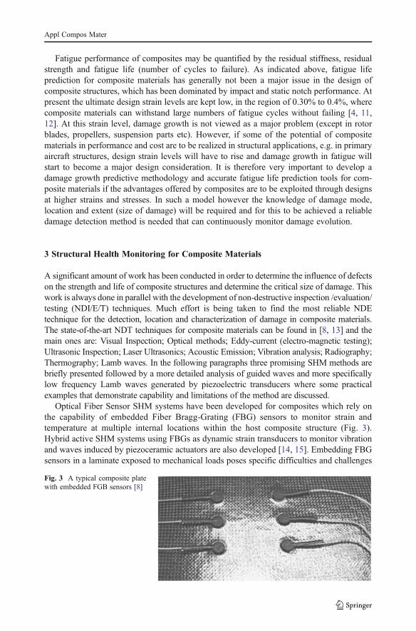
Optical Fiber Sensor SHM systems have been developed for composites which rely onthe capability of embedded Fiber Bragg-Grating (FBG) sensors to monitor strain andtemperature at multiple internal locations within the host composite structure (Fig. 3).Hybrid active SHM systems using FBGs as dynamic strain transducers to monitor vibrationand waves induced by piezoceramic actuators are also developed [14, 15]. Embedding FBGsensors in a laminate exposed to mechanical loads poses specific difficulties and challenges
Fig. 3 A typical composite platewith embedded FGB sensors [8]
Appl Compos Mater
which require solution. The method used to ingress/egress the optical fiber into and out ofthe laminate is important for the sensor performance. The effect of non-unidirectionalresidual and thermal stress on the fiber spectral peak further complicates the response ofFiber Bragg Gratings embedded in a composite laminate which deviates from the idealbehavior of bonded FBGs in room temperature. The behavior of FBGs in compositesespecially under elevated temperature conditions needs to be further investigated andoptimized before the technique can be applied in service. Also the effect of the embeddeddevices on the strength/stiffness of the laminated structure requires further attention, sinceunder thermo-mechanical loading damage in the form of delamination can be triggered.
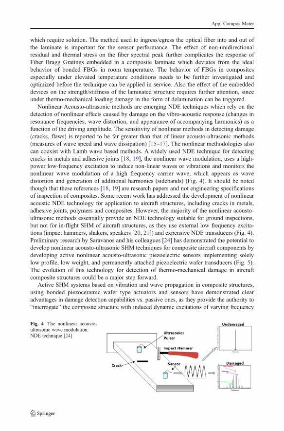
Nonlinear Acousto-ultrasonic methods are emerging NDE techniques which rely on thedetection of nonlinear effects caused by damage on the vibro-acoustic response (changes inresonance frequencies, wave distortion, and appearance of accompanying harmonics) as afunction of the driving amplitude. The sensitivity of nonlinear methods in detecting damage(cracks, flaws) is reported to be far greater than that of linear acousto-ultrasonic methods(measures of wave speed and wave dissipation) [15–17]. The nonlinear methodologies alsocan coexist with Lamb wave based methods. A widely used NDE technique for detectingcracks in metals and adhesive joints [18, 19], the nonlinear wave modulation, uses a high-power low-frequency excitation to induce non-linear waves or vibrations and monitors thenonlinear wave modulation of a high frequency carrier wave, which appears as wavedistortion and generation of additional harmonics (sidebands) (Fig. 4). It should be notedthough that these references [18, 19] are research papers and not engineering specificationsof inspection of composites. Some recent work has addressed the development of nonlinearacoustic NDE technology for application to aircraft structures, including cracks in metals,adhesive joints, polymers and composites. However, the majority of the nonlinear acousto-ultrasonic methods essentially provide an NDE technology suitable for ground inspections,but not for in-flight SHM of aircraft structures, as they use external low frequency excita-tions (impact hammers, shakers, speakers [20, 21]) and expensive NDE transducers (Fig. 4).Preliminary research by Saravanos and his colleagues [24] has demonstrated the potential todevelop nonlinear acousto-ultrasonic SHM techniques for composite aircraft components bydeveloping active nonlinear acousto-ultrasonic piezoelectric sensors implementing solelylow profile, low weight, and permanently attached piezoelectric wafer transducers (Fig. 5).The evolution of this technology for detection of thermo-mechanical damage in aircraftcomposite structures could be a major step forward.
Active SHM systems based on vibration and wave propagation in composite structures,using bonded piezoceramic wafer type actuators and sensors have demonstrated clearadvantages in damage detection capabilities vs. passive ones, as they provide the authority to“interrogate” the composite structure with induced dynamic excitations of varying frequency
Fig. 4 The nonlinear acousto-ultrasonic wave modulationNDE technique [24]
Appl Compos Mater
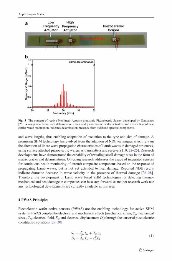
and wave lengths, thus enabling adaptation of excitation to the type and size of damage. Apromising SHM technology has evolved from the adaption of NDE techniques which rely onthe alteration of linear wave propagation characteristics of Lamb waves in damaged structures,using surface attached piezoelectric wafers as transmitters and receivers [10, 22–25]. Researchdevelopments have demonstrated the capability of revealing small damage sizes in the form ofmatrix cracks and delaminations. On-going research addresses the usage of integrated sensorsfor continuous health monitoring of aircraft composite components based on the response ofpropagating Lamb waves, but is not yet extended to heat damage. Reported NDE resultsindicate dramatic decrease in wave velocity in the presence of thermal damage [26–28].Therefore, the development of Lamb wave based SHM technologies for detecting thermo-mechanical and heat damage in composites can be a step forward, as neither research work norany technological developments are currently available in this area.
4 PWAS Principles
Piezoelectric wafer active sensors (PWAS) are the enabling technology for active SHMsystems. PWAS couples the electrical andmechanical effects (mechanical strain, Sij, mechanicalstress, Tkl, electrical field, Ek, and electrical displacementDj) through the tensorial piezoelectricconstitutive equations [29, 30]
Sij ¼ sEijklTkl þ dkijEk
Dj ¼ djklTkl þ "TjkEkð1Þ
Fig. 5 The concept of Active Nonlinear Acousto-ultrasonic Piezoelectric Sensor developed by Saravanos[25]. a composite beam with delamination crack and piezoceramic wafer actuators and sensor b nonlinearcarrier wave modulation indicates delamination presence from sideband spectral components
Appl Compos Mater
where, sEijkl is the mechanical compliance of the material measured at zero electric field (E00),
"Tjk is the dielectric permittivity measured at zeromechanical stress (T00), and dkij represents the
piezoelectric coupling effect. As a transmitter, PWAS utilize the d31 coupling between trans-verse electric field and in-plane strain to generate high-frequency ultrasonic waves in thestructure. As a receiver, PWAS utilize the d31 coupling between in-plane strain and transverseelectric field to convert the ultrasonic waves into high-frequency electric signals.
Just like conventional ultrasonic transducers, PWAS utilize the piezoelectric effect togenerate and receive ultrasonic waves. However, PWAS ultrasonic transducers are funda-mentally different from conventional ultrasonic transducers in several aspects:
1. PWAS are firmly coupled with the structure through an adhesive bonding, whereasconventional ultrasonic transducers are weakly coupled through gel, water, or air.
2. Conventional ultrasonic transducers act through surface tapping, i.e., by applyingvibration pressure to the structural surface. PWAS transducers act through in-planecoupling with the structural surface.
3. PWAS transducers are strain coupled with the structural surface. This allows the PWAStransducers to have a greater efficiency then conventional ultrasonic transducers intransmitting and receiving ultrasonic and guided waves (surface acoustic waves andLamb waves).
4. PWAS are non-resonant devices that can be tuned selectively into several guided Lamb-wave modes, whereas conventional ultrasonic transducers are resonant narrow-banddevices. With PWAS transducers, optimum excitation and detection takes place whenthe PWAS length is in certain ratios with the wavelength of the guided wave modes.
5. PWAS transducers cannot be considered in the same class as acoustic emission (AE)sensors because AE sensors are passive devices which only detect the elastic wavescreated by other events (e.g., elastic waves created when a crack advances in a materialcreating energy release events). In contrast, PWAS transducers can both detect andgenerate elastic waves, i.e., they are active sensors.
6. PWAS are inexpensive and can be deployed in large quantities on the structure, whereasconventional ultrasonic transducers are expensive and used one at a time.
By using Lamb waves in a thin-wall structure, one can detect structural anomaly, i.e.,cracks, corrosions, delaminations, and other damage. Because of the physical, mechanical,and piezoelectric properties of PWAS transducers, they act as both transmitters and receiversof Lamb waves traveling through the structure. Upon excitation with an electric signal, thePWAS generate Lamb waves in a thin-wall structure. The generated Lamb waves travelthrough the structure and are reflected or diffracted by the structural boundaries, disconti-nuities, and damage. The reflected or diffracted waves arrive at the PWAS where they aretransformed into electric signals.
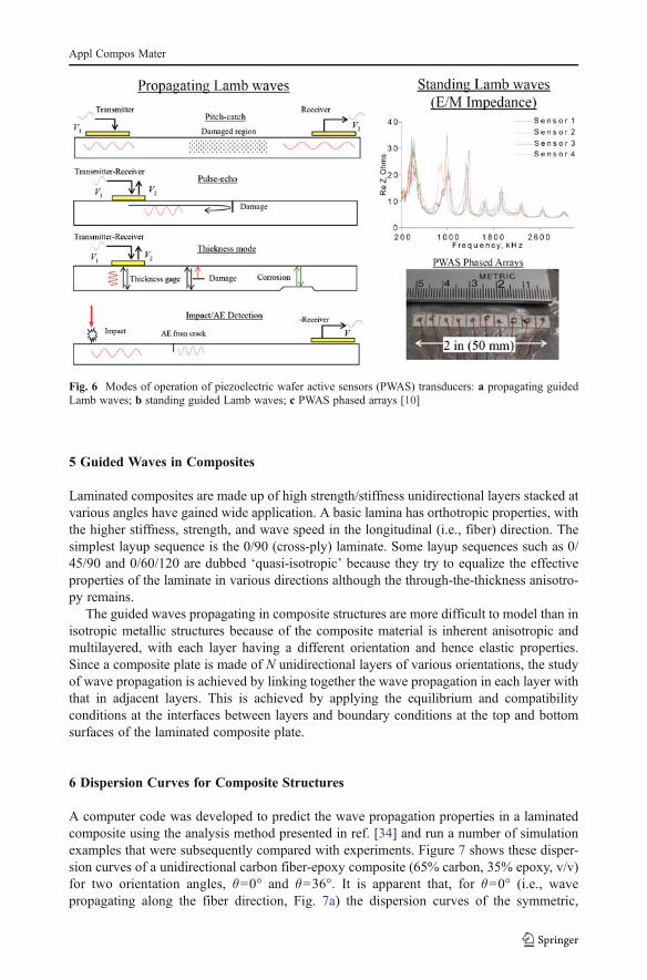
PWAS transducers can serve several purposes [10, 31–33]: (a) high-bandwidth strainsensors; (b) high-bandwidth wave exciters and receivers; (c) resonators; (d) embeddedmodal sensors with the electromechanical (E/M) impedance method. The PWAS transducershave various modes of operation (Fig. 6): (i) active sensing of far-field damage using pulse-echo, pitch-catch, and phased-array methods, (ii) active sensing of near-field damage usinghigh-frequency E/M impedance method and thickness-gage mode, and (iii) passive sensingof damage-generating events through detection of low-velocity impacts and acoustic emis-sion at the tip of advancing cracks. Damage detection using PWAS phased arrays can detectboth broadside and offside cracks independently with scanning beams emitting from acentral location.
Appl Compos Mater
5 Guided Waves in Composites
Laminated composites are made up of high strength/stiffness unidirectional layers stacked atvarious angles have gained wide application. A basic lamina has orthotropic properties, withthe higher stiffness, strength, and wave speed in the longitudinal (i.e., fiber) direction. Thesimplest layup sequence is the 0/90 (cross-ply) laminate. Some layup sequences such as 0/45/90 and 0/60/120 are dubbed ‘quasi-isotropic’ because they try to equalize the effectiveproperties of the laminate in various directions although the through-the-thickness anisotro-py remains.
The guided waves propagating in composite structures are more difficult to model than inisotropic metallic structures because of the composite material is inherent anisotropic andmultilayered, with each layer having a different orientation and hence elastic properties.Since a composite plate is made of N unidirectional layers of various orientations, the studyof wave propagation is achieved by linking together the wave propagation in each layer withthat in adjacent layers. This is achieved by applying the equilibrium and compatibilityconditions at the interfaces between layers and boundary conditions at the top and bottomsurfaces of the laminated composite plate.
6 Dispersion Curves for Composite Structures
A computer code was developed to predict the wave propagation properties in a laminatedcomposite using the analysis method presented in ref. [34] and run a number of simulationexamples that were subsequently compared with experiments. Figure 7 shows these disper-sion curves of a unidirectional carbon fiber-epoxy composite (65% carbon, 35% epoxy, v/v)for two orientation angles, θ00° and θ036°. It is apparent that, for θ00° (i.e., wavepropagating along the fiber direction, Fig. 7a) the dispersion curves of the symmetric,
Fig. 6 Modes of operation of piezoelectric wafer active sensors (PWAS) transducers: a propagating guidedLamb waves; b standing guided Lamb waves; c PWAS phased arrays [10]
Appl Compos Mater
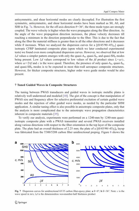
antisymmetric, and shear horizontal modes are clearly decoupled. For illustration the firstsymmetric, antisymmetric, and shear horizontal modes have been marked as S0, A0, andSH0 in Fig. 7a. However, for the off-axis direction θ036°, the three mode types are stronglycoupled. The wave velocity is higher when the wave propagates along the fiber direction. Asthe angle of the wave propagation direction increases, the phase velocity decreases tillreaching a minimum in the direction perpendicular to the fiber. This is due to the fact thatalong the fiber the material stiffness is greater than in all the other directions and it decreaseswhile θ increases. When we analyzed the dispersion curves for a [(0/45/90/-45)2s] quasi-isotropic CFRP laminated composite plate (upon which we later conducted experimentaltests) we found even more complicated dispersion curves. However, we observed that at lowξd values a simpler pattern emerges with only the quasi-A0, quasi-S0, and quasi-SH0 modesbeing present. Low ξd values correspond to low values of the fd product since ξ0ω/c,where ω02πf and c is the wave speed. Therefore, the presence of only quasi-A0, quasi-S0,and quasi-SH0 modes is to be expected in most thin-wall aerospace composite structures.However, for thicker composite structures, higher order wave guide modes would be alsopresent.
7 Tuned Guided Waves in Composite Structures
The tuning between PWAS transducers and guided waves in isotropic metallic plates isrelatively well understood and modeled [10]. The gist of the concept is that manipulation ofPWAS size and frequency allow for selective preferential excitation of certain guided wavemodes and the rejection of other guided wave modes, as needed by the particular SHMapplication. A similar tuning effect is also possible in anisotropic composite plates, only thatthe analysis is more complicated due to the anisotropic wave propagation characteristicsinherent in composite materials [35].
To verify our analysis, experiments were performed on a 1240-mm by 1240-mm quasi-isotropic composite plate with a PWAS transmitter and several PWAS receivers installedalong various directions with respect to the fiber orientation in the top layer of the compositeplate. The plate had an overall thickness of 2.25 mm; the plate of a [(0/45/90/-45)2]S layupwas fabricated from the T300/5208 carbon fiber unidirectional prepreg. Figure 8 shows the
d
c, m/s
A0
S0
SH0
c, m/s
0 1 2 3 4 5 6 7 80
1000
2000
3000
4000
5000
6000
d
a b
Fig. 7 Dispersion curves for unidirectional 65/35 carbon fiber-epoxy plate: a θ00°; b θ036°. Note: c is thewave speed in m/s; ξd is the dimensionless wavenumber-half thickness product
Appl Compos Mater
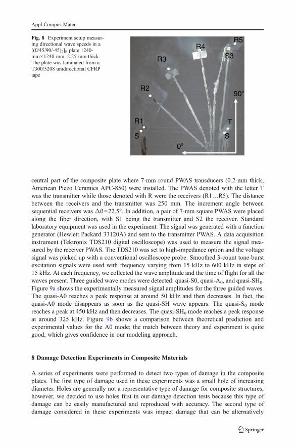
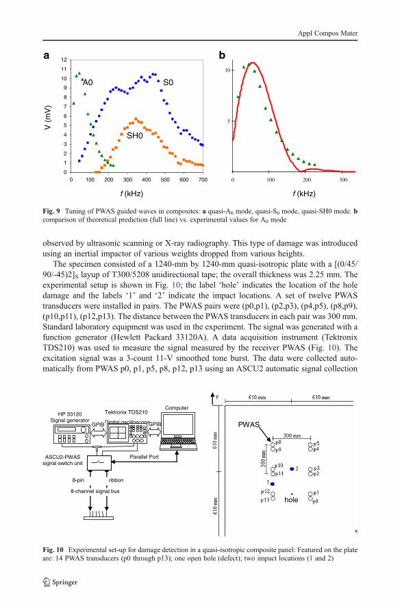
central part of the composite plate where 7-mm round PWAS transducers (0.2-mm thick,American Piezo Ceramics APC-850) were installed. The PWAS denoted with the letter Twas the transmitter while those denoted with R were the receivers (R1…R5). The distancebetween the receivers and the transmitter was 250 mm. The increment angle betweensequential receivers was Δθ022.5°. In addition, a pair of 7-mm square PWAS were placedalong the fiber direction, with S1 being the transmitter and S2 the receiver. Standardlaboratory equipment was used in the experiment. The signal was generated with a functiongenerator (Hewlett Packard 33120A) and sent to the transmitter PWAS. A data acquisitioninstrument (Tektronix TDS210 digital oscilloscope) was used to measure the signal mea-sured by the receiver PWAS. The TDS210 was set to high-impedance option and the voltagesignal was picked up with a conventional oscilloscope probe. Smoothed 3-count tone-burstexcitation signals were used with frequency varying from 15 kHz to 600 kHz in steps of15 kHz. At each frequency, we collected the wave amplitude and the time of flight for all thewaves present. Three guided wave modes were detected: quasi-S0, quasi-A0, and quasi-SH0.Figure 9a shows the experimentally measured signal amplitudes for the three guided waves.The quasi-A0 reaches a peak response at around 50 kHz and then decreases. In fact, thequasi-A0 mode disappears as soon as the quasi-SH wave appears. The quasi-S0 modereaches a peak at 450 kHz and then decreases. The quasi-SH0 mode reaches a peak responseat around 325 kHz. Figure 9b shows a comparison between theoretical prediction andexperimental values for the A0 mode; the match between theory and experiment is quitegood, which gives confidence in our modeling approach.
8 Damage Detection Experiments in Composite Materials
A series of experiments were performed to detect two types of damage in the compositeplates. The first type of damage used in these experiments was a small hole of increasingdiameter. Holes are generally not a representative type of damage for composite structures;however, we decided to use holes first in our damage detection tests because this type ofdamage can be easily manufactured and reproduced with accuracy. The second type ofdamage considered in these experiments was impact damage that can be alternatively
0o
90o
T
S
R1
S
R3
R2
R4 R5
S3
Fig. 8 Experiment setup measur-ing directional wave speeds in a[(0/45/90/-45)2]S plate 1240-mm×1240-mm, 2.25-mm thick.The plate was laminated from aT300/5208 unidirectional CFRPtape
Appl Compos Mater
observed by ultrasonic scanning or X-ray radiography. This type of damage was introducedusing an inertial impactor of various weights dropped from various heights.
The specimen consisted of a 1240-mm by 1240-mm quasi-isotropic plate with a [(0/45/90/-45)2]S layup of T300/5208 unidirectional tape; the overall thickness was 2.25 mm. Theexperimental setup is shown in Fig. 10; the label ‘hole’ indicates the location of the holedamage and the labels ‘1’ and ‘2’ indicate the impact locations. A set of twelve PWAStransducers were installed in pairs. The PWAS pairs were (p0,p1), (p2,p3), (p4,p5), (p8,p9),(p10,p11), (p12,p13). The distance between the PWAS transducers in each pair was 300 mm.Standard laboratory equipment was used in the experiment. The signal was generated with afunction generator (Hewlett Packard 33120A). A data acquisition instrument (TektronixTDS210) was used to measure the signal measured by the receiver PWAS (Fig. 10). Theexcitation signal was a 3-count 11-V smoothed tone burst. The data were collected auto-matically from PWAS p0, p1, p5, p8, p12, p13 using an ASCU2 automatic signal collection
ComputerTektronix TDS210
Digital oscilloscopeGPIB GPIB
Parallel Port
HP 33120 Signal generator
ASCU2-PWAS signal switch unit
8-channel signal bus
8-pin ribbon
y
PWAS
hole
x
Fig. 10 Experimental set-up for damage detection in a quasi-isotropic composite panel: Featured on the plateare: 14 PWAS transducers (p0 through p13); one open hole (defect); two impact locations (1 and 2)
0
1
2
3
4
5
6
7
8
9
10
11
12
f (kHz)
V (
mV
)
0 100 200 300 400 500 600 700
A0 S0
SH0
f (kHz)
0 100 200 300
5
10
a b
Fig. 9 Tuning of PWAS guided waves in composites: a quasi-A0 mode, quasi-S0 mode, quasi-SH0 mode. bcomparison of theoretical prediction (full line) vs. experimental values for A0 mode
Appl Compos Mater
unit [36]. The ASCU2 unit was purpose-built to enable to collection of multiple signals inround-robin fashion under computer control. Full details of ASCU2 unit are provided in ref.[36]. Each PWAS was in turn transmitter and receiver. Three frequencies were chosenaccording to the wave tuning principle: (i) f054 kHz, when only the A0 mode is present;(ii) f0225 kHz, when only the S0 mode is present; and (iii) f0255 kHz, when the S0 modehas maximum amplitude. Four sequential baseline readings were taken with the plateundamaged. Subsequent readings were taken after each damage type was applied to theplate.
8.1 Hole Damage Detection in a Quasi-Isotropic Composite Plate
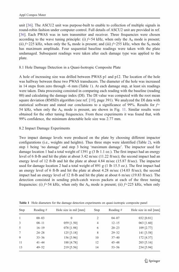
A hole of increasing size was drilled between PWAS p1 and p12. The location of the holewas halfway between these two PWAS transducers. The diameter of the hole was increasedin 14 steps from zero through ~6 mm (Table 1). At each damage step, at least six readingswere taken. Data processing consisted in comparing each reading with the baseline (reading00) and calculating the damage index (DI). The DI value was computed with the root meansquare deviation (RMSD) algorithm (see ref. [10], page 391). We analyzed the DI data withstatistical software and stated our conclusions to a significance of 99%. Results for f054 kHz, when only the A0 mode is present, are shown in Fig. 11. Similar results wereobtained for the other tuning frequencies. From these experiments it was found that, with99% confidence, the minimum detectable hole size was 2.77 mm.
8.2 Impact Damage Experiments
Two impact damage levels were produced on the plate by choosing different impactorconfigurations (i.e., weights and heights). Thus three steps were identified (Table 2), withstep 1 being ‘no damage’ and step 3 being ‘maximum damage’. The impactor used fordamage location 1 had a total weight of 1391 g (3 lb 1.1 oz.). The first impact had an energylevel of 6 ft-lb and hit the plate at about 3.42 m/sec (11.22 ft/sec); the second impact had anenergy level of 12 ft-lb and hit the plate at about 4.84 m/sec (15.87 ft/sec). The impactorused for damage location 2 had a total weight of 891 g (1 lb 15.5 oz.). The first impact hadan energy level of 6 ft-lb and hit the plate at about 4.28 m/sec (14.03 ft/sec); the secondimpact had an energy level of 12 ft-lb and hit the plate at about 6 m/sec (19.83 ft/sec). Thedetection consisted in sending pitch-catch waves packets at each of the three tuningfrequencies: (i) f054 kHz, when only the A0 mode is present; (ii) f0225 kHz, when only
Table 1 Hole diameters for the damage detection experiments on quasi-isotropic composite panel
Step Reading # Hole size in mil [mm] Step Reading # Hole size in mil [mm]
1 00–03 0 2 04–07 032 [0.81]
3 08–11 059 [1.50] 4 12–15 063 [1.60]
5 16–19 078 [1.98] 6 20–23 109 [2.77]
7 24–28 125 [3.18] 8 29–32 141 [3.58]
9 33–36 156 [3.96] 10 37–40 172 [4.37]
11 41–44 188 [4.78] 12 45–48 203 [5.16]
13 49–52 219 [5.56] 14 53–56 234 [5.94]
Appl Compos Mater
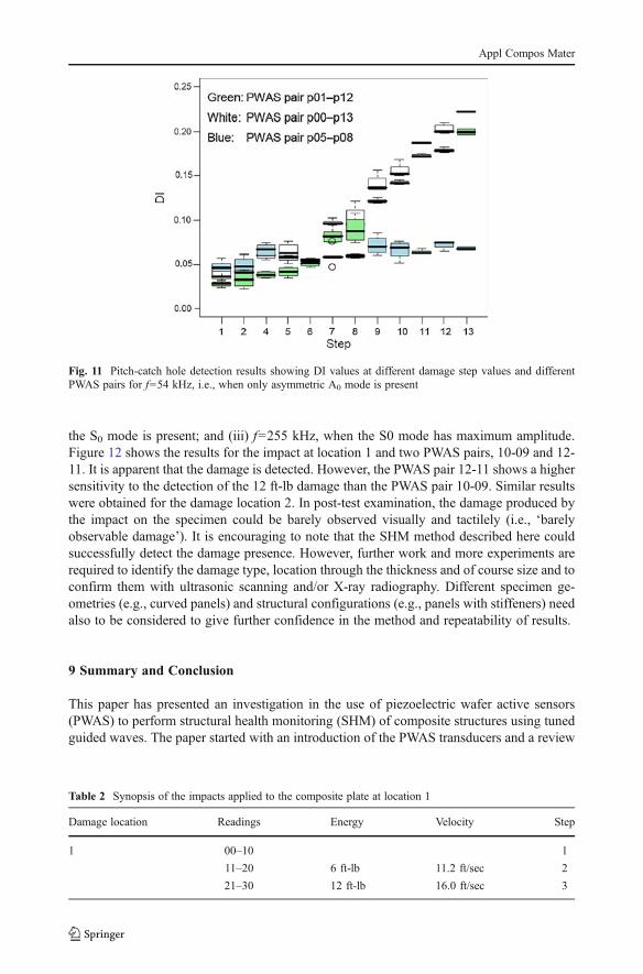
the S0 mode is present; and (iii) f0255 kHz, when the S0 mode has maximum amplitude.Figure 12 shows the results for the impact at location 1 and two PWAS pairs, 10-09 and 12-11. It is apparent that the damage is detected. However, the PWAS pair 12-11 shows a highersensitivity to the detection of the 12 ft-lb damage than the PWAS pair 10-09. Similar resultswere obtained for the damage location 2. In post-test examination, the damage produced bythe impact on the specimen could be barely observed visually and tactilely (i.e., ‘barelyobservable damage’). It is encouraging to note that the SHM method described here couldsuccessfully detect the damage presence. However, further work and more experiments arerequired to identify the damage type, location through the thickness and of course size and toconfirm them with ultrasonic scanning and/or X-ray radiography. Different specimen ge-ometries (e.g., curved panels) and structural configurations (e.g., panels with stiffeners) needalso to be considered to give further confidence in the method and repeatability of results.
9 Summary and Conclusion
This paper has presented an investigation in the use of piezoelectric wafer active sensors(PWAS) to perform structural health monitoring (SHM) of composite structures using tunedguided waves. The paper started with an introduction of the PWAS transducers and a review
Fig. 11 Pitch-catch hole detection results showing DI values at different damage step values and differentPWAS pairs for f054 kHz, i.e., when only asymmetric A0 mode is present
Table 2 Synopsis of the impacts applied to the composite plate at location 1
Damage location Readings Energy Velocity Step
1 00–10 1
11–20 6 ft-lb 11.2 ft/sec 2
21–30 12 ft-lb 16.0 ft/sec 3
Appl Compos Mater
of the various ways in which PWAS may detect damage using traveling guided waves,standing waves, and phased arrays. Next, the paper discussed the challenge of guided wavepropagation in composite materials and presented some analytical predictions of the disper-sion curves which are more complicated that for isotropic metallic materials. However, itwas shown that the wave tuning effect initially identified for metallic materials can also beidentified in composite materials; tuning measurements performed on a composite platewere presented in comparison with theoretical predictions.
After discussing briefly the damage modes commonly met in structural composites, thepaper presented experimental results obtained on a large composite plate. Two types ofdefects/damage were considered: (i) open hole; and (ii) low velocity impact damage. Thedetection method used in these experiments was pitch-catch with three tuning frequencies:(i) f054 kHz, when only the asymmetric A0 mode is present; (ii) f0225 kHz, when only thesymmetric S0 mode is present; and (iii) f0255 kHz, when the S0 mode has maximumamplitude. It was found that, with 99% confidence, the minimum detectable hole size was2.77 mm. In the impact damage experiments, it was found that tuned A0 guided wave modewere much more effective in detecting impact damage in quasi-isotropic carbon-epoxyplates than S0 mode. It was also found that, because of the anisotropy of the compositematerial, the directional placement of the PWAS transducers plays an important role in theirdetection capabilities.
However, the results presented in this paper are exploratory in nature and preliminary. Itshould also be said that without a fail-safe capability the utility of the proposed methodcould be limited. Propagation of the various acoustic waves in a composite structure is a verycomplex process as most structural components do not have the simple shape one associateswith the simple straight test specimens used in this paper. In addition, there are the numerousreflections and mode conversions at boundaries that can complicate the signals and signalanalysis. Further research needs to be done to better understand the interaction of guidedwaves with damage in composite materials and how various guide-wave types interact withvarious types of damage such as delamination [37] and fiber breakage, especially fibermicrobuckling that is observed when the laminate is loaded in uniaxial compression [38].Two technical reports on aircraft damage tolerance requirements and aircraft structuralintegrity that may be useful to the reader/researcher can be found in references [39, 40].
6 ft-lb12 ft-lb
6 ft-lb
12 ft-lb
DI
Fig. 12 Detection of impact damage at location 1: DI values as a function of the damage level for PWAS pairsp9-p10 and p11-p12 (f054 kHz, i.e., when only A0 mode is present)
Appl Compos Mater
References
1. Marshal, P., Rezai, A.: “Use of composites in aerostructures”, Newsletter of the European Society forComposite Materials (ESCM), issue 3, May (2000)
2. Bar-Cohen, Y.: Emerging NDT technologies and challenges at the beginning of the third millenium, part1. Mater Eval 58(1), 17–26 (2000)
3. Bar-Cohen, Y.: Emerging NDT technologies and challenges at the beginning of the third millenium, part2. Mater Eval 58(2), 141–150 (2000)
4. Soutis, C.: Fibre reinforced composites in aircraft construction. Prog Aerosp Sci 41(2), 143–151 (2005)5. Davies, G.A.O., Zhang, X.: Impact damage prediction in carbon composite structures. Int J Impact Eng 16
(1), 149–170 (1995)6. Davies, G.A.O.: ‘Aerospace composite structures in the USA’. Report for the International Technology
Service (Overseas Missions Unit) of the DTI, UK (1999)7. Sohn, H., Farrar, C.R., Hemez, F.M., Shunk, D.D., Stinemates, S.W., Nadler, B.R., Czarnecki, J.J.: “A
review of structural health monitoring literature form 1996–2001,” Los Alamos National Laboratoryreport LA-13976-MS (2004)
8. Boller, C., Chang, F-K., Fujino, Y.: Encyclopedia of structural health monitoring, J. Wiley & Sons Ltd(2009)
9. Raghavan, A., Cesnik, C.E.S.: Review of guided-wave structural health monitoring. Shock Vib Digest 39(2), 91–114 (2007)
10. Giurgiutiu, V.: Structural health monitoring with piezoelectric wafer active sensors, Elsevier AcademicPress, 760 pages, ISBN 978-0120887606 (2008)
11. Kashtalyan, M., Soutis, C.: Stiffness degradation in cross-ply laminates damaged by transverse crackingand splitting. Composites Part A 31(4), 335–351 (2000)
12. Kashtalyan, M., Soutis, C.: Analysis of local delaminations in composite laminates with angle ply matrixcracks. Int J Solid Struct 39(6), 1515–1537 (2002)
13. Diamanti, K., Soutis, C.: Structural health monitoring techniques for aircraft composite structures. ProgAerosp Sci 46(8), 343–352 (2010)
14. Rogers, A.J., Handerek, V.A., Farhadiroushan, M., Feced, R., Parker, T.R., Parvaneh, F.: “Advances indistributed optical fiber sensing,” Proc. SPIE, 3483, 5–10 (1985)
15. Culshaw, B., Dakin, J.: Optical Fiber Sensors: system and applications, vol. II. Artech House, Norwood(1989)
16. Diaz Valdes, S.H., Soutis, C.: Health monitoring of composites using lamb waves generated by piezo-electric devices. Plast Rubber Compos 29(9), 475–481 (2000)
17. Giurgiutiu, V., Zagrai, A., Bao, J.: Damage identification in aging aircraft structures with piezoelectricwafer active sensors. J Intell Mater Syst Struct 15(9–10), 673–687 (2004)
18. Hirsekorn, S.: Quality assessment of bonded interfaces by nonlinear ultrasonic techniques. Ultrasonics 39,57–68 (2001)
19. Van Den Abeele, K.E., Johnson, P.A., Sutin, A.: Nonlinear Elastic Wave Spectroscopy (NEWS) techni-ques to discern material damage, part I nonlinear wave modulation spectroscopy. Res Nondestr Eval 12(1), 17–30 (2000)
20. Donskoy, D., Sutin, A., Ekimov, A.: Non linear acoustic interaction on contact Interfaces and its use fornon destructive testing. NDT & E International 34(4), 231–238 (2001)
21. Parsons, J., Staszewski, W.J.: Nonlinear acoustics with low-profile piezoceramic excitation for crackdetection in metallic structures. Smart Mater Struct 15(4), 1110–1118 (2006)
22. Keilers, C.H., Chang, F.-K.: Identifying delamination in composite beam using built-in piezoelectrics. JIntell Mater Syst Struct 6(5), 647–672 (1995)
23. Diaz Valdes, S.H., Soutis, C.: Real-time non-destructive evaluation of fiber composite laminates usinglow-frequency Lamb waves. J Acoust Soc Am 111(5), 2026–2033 (2002)
24. Chrysochoidis, N.A., Barouni, A.K., Saravanos, D.A.: On the delamination detection in composite beamswith active piezoelectric sensors using non-linear ultrasonics, Proceedings of SPIE - Smart Structures andMaterials & Nondestructive Evaluation and Health Monitoring, art. no. 729552 (2009)
25. Chrysochoidis, N.A., Barouni, A.K., Saravanos, D.A.: Delamination detection in composites using wavemodulation spectroscopy with a novel active nonlinear acousto-ultrasonic piezoelectric sensor. J Intel MatSyst Str 22(18), 2193–2206 (2011)
26. Sealea, M.D., Smith, B.T., Prosser, W.H.: Lamb wave assessment of fatigue and thermal damage incomposites. J Acoust Soc Am 103(5), 2416–2424 (1998)
27. Sealea, M.D., Madaras, E.I.: Lamb wave characterization of the effects of long-term thermal-mechanicalaging on composite stiffness. J Acoust Soc Am 106(3), 1346–1352 (1999)
Appl Compos Mater
28. Van Den Abeele, K., Le Bas, P.Y., Van Damme, B.: Quantification of material nonlinearity in relation tomicrodamage density using nonlinear reverberation spectroscopy: Experimental and theoretical study. JAcoust Soc Am 126(3), 963–972 (2009)
29. ANSI/IEEE Std. 176: IEEE Standard on Piezoelectricity, the Institute of Electrical and ElectronicsEngineers, Inc., New York (1987)
30. Auld, B.A.: “Acoustic Fields and waves in solids”, Vol. 1 and 2, John Wiley & Son (1990)31. Giurgiutiu, V.: “In-situ structural health monitoring, diagnostics, and prognostics system utilizing thin
piezoelectric sensors”. U.S. Patent Office #7,024,315 of April 8, (2006)32. Giurgiutiu, V., Bao, J., Zagrai, A.N.: “Structural health monitoring system utilizing guided Lamb waves
embedded ultrasonic structural radar”, U.S. Patent Office #6,996,480 of February 7 (2006)33. Giurgiutiu, V., Xu, B.: “Self-Processing Integrated Damage Assessment Sensor for Structural Health
Monitoring (SPIDAS)”, U.S. Patent Office #7,174,255 of Feb. 6 (2007)34. Nayfeh, A.H.: “Wave propagation in layered anisotropic media with application to composites.” Elsevier
(1995)35. Santoni-Bottai, G., Giurgiutiu, V.: “Exact shear-lag solution for guided waves tuning with piezoelectric
wafer active sensors”, AIAA Journal, manuscript # 2010-05-J050667 (in press) (2010)36. Giurgiutiu, V., Liu, W.: “ASCU-PWAS—Automatic Signal Collection Unit for PWAS-based Structural
Health Monitoring” USC-IPMO, Disclosure ID No. 00433 of 4/23/2004 (2004)37. Kashtalyan, M., Soutis, C.: Analysis of composite laminates with intra- and interlaminar damage. Prog
Aerosp Sci 41(2), 152–173 (2005)38. Berbinau, P., Soutis, C., Guz, I.A.: Compressive failure of 0° unidirectional CFRP laminates by fibre
microbuckling. Composites Sci Technol 59(9), 1451–1455 (1999)39. “Military Specification: Airplane Damage Tolerance Requirements”, Report No. MIL A 83444, Wright
Patterson Air Force Base, United State Air Force Aeronautical Systems Division (1974)40. “Standard Practice: Aircraft Structural Integrity Program (ASIP)”, Report No. MIL STD 1530B, Wright
Patterson Air Force Base, United State Air Force Aeronautical Systems Division (2004)
Appl Compos Mater