injection: hadron beams - cern publishing
TRANSCRIPT
Injection: Hadron Beams
C. BraccoCERN, Geneva, Switzerland
AbstractThe injection process involves placing a particle beam in a circular hadronaccelerator or accumulator at the right time, in the correct orbit, with the rightphase space parameters, and minimizing beam losses. Injection insertions areamong the most complex parts of an accelerator and, if not properly designed,can compromise the beam quality and, in the worst case, cause machine dam-age. An overview of the main principles and hardware used for single, multi-turn, and charge exchange injection systems is presented. Common injectionerrors and their consequences are explained, together with the definition ofthe machine aperture and the concept of protection devices. Examples of un-conventional injection processes are introduced.
KeywordsSingle turn; multiturn; charge exchange; mismatch; aperture; machine pro-tection.
1 IntroductionThe performance of a hadron collider or accumulator depends on the minimum achievable beam size andthe maximum storable intensity. The injection process has a strong influence on both these parametersand, if not properly performed, it might downgrade the effective achievement of a machine. Minimizationof the beam size involves positioning the injected beam on the right orbit, with the correct timing, andwith matched optics parameters with respect to the ring lattice at the injection point. Small injectionlosses are then a basic requirement for an efficient transfer into a ring and to avoid any risk of beam-induced machine damage.
Different challenges are encountered, depending on the energy of the injected beams. In the low-energy regime (i.e., ⇠10 MeV for hadrons), the main concern comes from space charge. Particles in abeam feel electromagnetic forces, which are produced by the beam itself. Assuming an unbunched beam,with a uniform charge density and a circular cross-section, each particle will experience an incoherenttransverse tune shift �Qx,y due to space charge, which is proportional to [1]:
�Qx,y /N
�2�"N, (1)
where N is the number of particles per unit length, � and � the relativistic factors and "N the r.m.s.normalized transverse emittance. The resulting tune spread can lead to an emittance blow-up and losses.The effect is stronger at low energy and for large energy densities and hence imposes a limit on themaximum achievable brightness.
Injections of ⇠100 GeV hadron beams are critical because of the large amount of stored energy(up to 2.4 MJ, which is equivalent to 0.5 kg of TNT, for the Large Hadron Collider (LHC) beams) andthe consequent disruptive power in the case of wrong handling. A proper choice and correct design ofthe injection system, which depends on the beam conditions and the main requirements of the receivingmachine, enable minimization of the aforementioned undesired effects and thus maximization of themachine performance while guaranteeing the required protection.
Proceedings of the CAS–CERN Accelerator School: Beam Injection, Extraction and Transfer, Erice, Italy, 10-19 March 2017, edited byB. Holzer, CERN Yellow Reports: School Proceedings, Vol. 5/2018, CERN-2018-008-SP (CERN, Geneva, 2018)
2519-8041 – c� CERN, 2018. Published by CERN under the Creative Common Attribution CC BY 4.0 Licence.https://doi.org/10.23730/CYRSP-2018-005.131
131
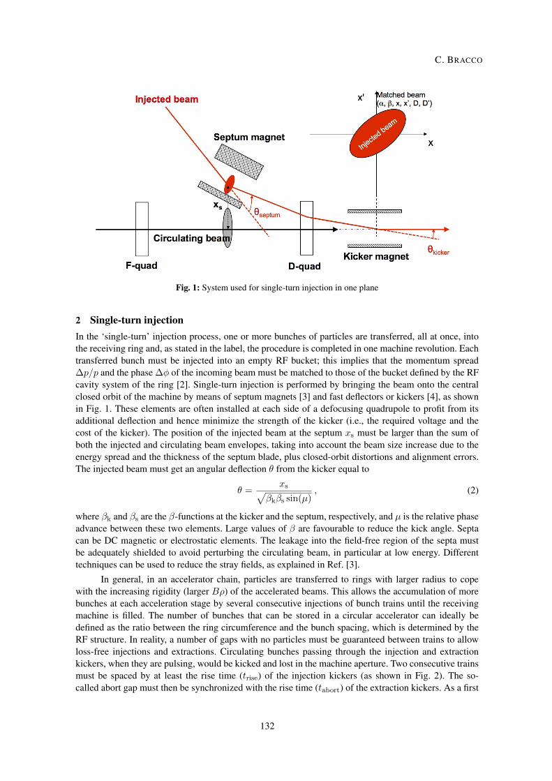
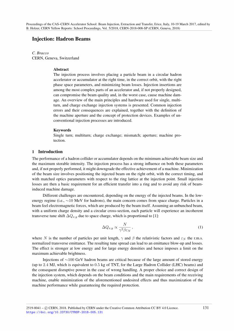
Fig. 1: System used for single-turn injection in one plane
2 Single-turn injectionIn the ‘single-turn’ injection process, one or more bunches of particles are transferred, all at once, intothe receiving ring and, as stated in the label, the procedure is completed in one machine revolution. Eachtransferred bunch must be injected into an empty RF bucket; this implies that the momentum spread�p/p and the phase �� of the incoming beam must be matched to those of the bucket defined by the RFcavity system of the ring [2]. Single-turn injection is performed by bringing the beam onto the centralclosed orbit of the machine by means of septum magnets [3] and fast deflectors or kickers [4], as shownin Fig. 1. These elements are often installed at each side of a defocusing quadrupole to profit from itsadditional deflection and hence minimize the strength of the kicker (i.e., the required voltage and thecost of the kicker). The position of the injected beam at the septum xs must be larger than the sum ofboth the injected and circulating beam envelopes, taking into account the beam size increase due to theenergy spread and the thickness of the septum blade, plus closed-orbit distortions and alignment errors.The injected beam must get an angular deflection ✓ from the kicker equal to
✓ =xsp
�k�s sin(µ), (2)
where �k and �s are the �-functions at the kicker and the septum, respectively, and µ is the relative phaseadvance between these two elements. Large values of � are favourable to reduce the kick angle. Septacan be DC magnetic or electrostatic elements. The leakage into the field-free region of the septa mustbe adequately shielded to avoid perturbing the circulating beam, in particular at low energy. Differenttechniques can be used to reduce the stray fields, as explained in Ref. [3].
In general, in an accelerator chain, particles are transferred to rings with larger radius to copewith the increasing rigidity (larger B⇢) of the accelerated beams. This allows the accumulation of morebunches at each acceleration stage by several consecutive injections of bunch trains until the receivingmachine is filled. The number of bunches that can be stored in a circular accelerator can ideally bedefined as the ratio between the ring circumference and the bunch spacing, which is determined by theRF structure. In reality, a number of gaps with no particles must be guaranteed between trains to allowloss-free injections and extractions. Circulating bunches passing through the injection and extractionkickers, when they are pulsing, would be kicked and lost in the machine aperture. Two consecutive trainsmust be spaced by at least the rise time (trise) of the injection kickers (as shown in Fig. 2). The so-called abort gap must then be synchronized with the rise time (tabort) of the extraction kickers. As a first
2
C. BRACCO
132
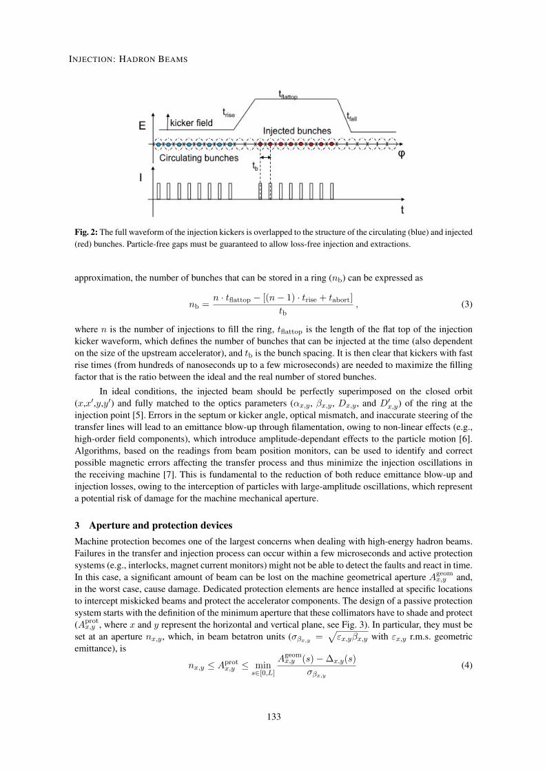
Fig. 2: The full waveform of the injection kickers is overlapped to the structure of the circulating (blue) and injected(red) bunches. Particle-free gaps must be guaranteed to allow loss-free injection and extractions.
approximation, the number of bunches that can be stored in a ring (nb) can be expressed as
nb =n · tflattop � [(n� 1) · trise + tabort]
tb, (3)
where n is the number of injections to fill the ring, tflattop is the length of the flat top of the injectionkicker waveform, which defines the number of bunches that can be injected at the time (also dependenton the size of the upstream accelerator), and tb is the bunch spacing. It is then clear that kickers with fastrise times (from hundreds of nanoseconds up to a few microseconds) are needed to maximize the fillingfactor that is the ratio between the ideal and the real number of stored bunches.
In ideal conditions, the injected beam should be perfectly superimposed on the closed orbit(x,x0,y,y0) and fully matched to the optics parameters (↵x,y, �x,y, Dx,y, and D0
x,y) of the ring at theinjection point [5]. Errors in the septum or kicker angle, optical mismatch, and inaccurate steering of thetransfer lines will lead to an emittance blow-up through filamentation, owing to non-linear effects (e.g.,high-order field components), which introduce amplitude-dependant effects to the particle motion [6].Algorithms, based on the readings from beam position monitors, can be used to identify and correctpossible magnetic errors affecting the transfer process and thus minimize the injection oscillations inthe receiving machine [7]. This is fundamental to the reduction of both reduce emittance blow-up andinjection losses, owing to the interception of particles with large-amplitude oscillations, which representa potential risk of damage for the machine mechanical aperture.
3 Aperture and protection devicesMachine protection becomes one of the largest concerns when dealing with high-energy hadron beams.Failures in the transfer and injection process can occur within a few microseconds and active protectionsystems (e.g., interlocks, magnet current monitors) might not be able to detect the faults and react in time.In this case, a significant amount of beam can be lost on the machine geometrical aperture Ageom
x,y and,in the worst case, cause damage. Dedicated protection elements are hence installed at specific locationsto intercept miskicked beams and protect the accelerator components. The design of a passive protectionsystem starts with the definition of the minimum aperture that these collimators have to shade and protect(Aprot
x,y , where x and y represent the horizontal and vertical plane, see Fig. 3). In particular, they must beset at an aperture nx,y, which, in beam betatron units (��x,y =
p"x,y�x,y with "x,y r.m.s. geometric
emittance), is
nx,y Aprotx,y min
s2[0,L]
Ageomx,y (s)��x,y(s)
��x,y
(4)
3
INJECTION: HADRON BEAMS
133
Fig. 3: Beam envelope with respect to machine’s geometrical aperture. The injection protection collimators mustshadow the aperture of the machine equipment, withstand direct beam impact, and reduce the downstream energydeposition to less than the damage limit.
where s is the longitudinal co-ordinate along a machine of length L and �x,y(s) is the maximum beamtransverse displacement:
�x,y(s) = COpeakx,y
s�x,y(s)
�maxx,y
+h�mechx,y (s) + �alignx,y (s)
i+k�Dx,y(s)�p+dsepx,y(s)+dinjx,y(s)+daxisx,y (s) . (5)
In Eq. 5, mechanical (�mechx,y ) and alignment (�alignx,y ) tolerances are added to the peak ring closed orbit
(COpeak), which is normalized with respect to the local and the maximum �-functions. A dispersiveterm is also considered where �p is the sum of the beam momentum offset and the maximum mo-mentum spread, k� is the �-beating correction factor, and Dx,y is the dispersion. The contribution oforbit displacements due to crossing and separation (dsepx,y), injection oscillations (dinjx,y), and offsets of themagnets with respect to the ring axis (daxisx,y ) are also taken into account [8]. As a general rule, the higherthe beam stored energy, which is defined as the number of particles multiplied by the energy per particle,the larger the margin between the area occupied by the beam and Ageom
x,y . Collimators should be set tointercept only miskicked or large-amplitude particles without interfering with the unperturbed injectedand circulating beams. Special attention must be used for superconducting machines to limit the numberof magnet quenches induced by beam losses.
The passive protection devices must withstand direct beam impacts and reduce energy deposition,owing to secondary showers, on the downstream elements to below the damage limit. The choice of thematerial of the absorbing blocks and the active length depend on the beam energy and intensity. Low-Zmaterials, like graphite, provide the best performance in terms of robustness but are quite transparent tosecondary showers. Protection collimators must be set at well-defined longitudinal positions to provide afull coverage of the transverse phase space. As an example, a system of three collimators (each made oftwo 1 m long graphite jaws) per plane, located at 60� relative phase advance, is installed at the end of thetransfer lines connecting the CERN Super Proton Synchrotron (SPS) to the LHC. This layout allows therequired phase space coverage to be guaranteed while minimizing the number of collimators (Fig. 4) [9].A >4 m long two-sided injection dump, composed of a sequence of low- and high-Z materials [9] to ab-sorb secondary showers, is installed in the LHC injection region at 90� phase advance from the injectionkicker. In the case of kicker failures, this dump cuts the particles with the largest amplitudes. The two-sided injection dump will be upgraded to cope with operation with high-brightness beams correspondingto 5 MJ stored energy per injection, which is at the limit of what materials can deal with, in terms ofrobustness and transmission. Material limitations might constrain the operation of future machines (e.g.,the Future Circular Collider (FCC)), limiting the beam intensity that can be transferred at once. This willincrease the number of injections required to fill the machine and, therefore, depending on the achievablerise time of the injection and extraction kickers, impact the total stored intensity [10, 11].
4
C. BRACCO
134
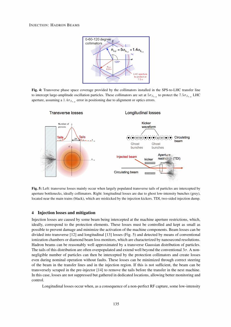
Fig. 4: Transverse phase space coverage provided by the collimators installed in the SPS-to-LHC transfer lineto intercept large-amplitude oscillation particles. These collimators are set at 5��x,y to protect the 7.5��x,y LHCaperture, assuming a 1.4��x,y error in positioning due to alignment or optics errors.
Fig. 5: Left: transverse losses mainly occur when largely populated transverse tails of particles are intercepted byaperture bottlenecks, ideally collimators. Right: longitudinal losses are due to ghost low-intensity bunches (grey),located near the main trains (black), which are miskicked by the injection kickers. TDI, two-sided injection dump.
4 Injection losses and mitigationInjection losses are caused by some beam being intercepted at the machine aperture restrictions, which,ideally, correspond to the protection elements. These losses must be controlled and kept as small aspossible to prevent damage and minimize the activation of the machine components. Beam losses can bedivided into transverse [12] and longitudinal [13] losses (Fig. 5) and detected by means of conventionalionization chambers or diamond beam loss monitors, which are characterized by nanosecond resolutions.Hadron beams can be reasonably well approximated by a transverse Gaussian distribution of particles.The tails of this distribution are often overpopulated and extend well beyond the conventional 3�. A non-negligible number of particles can then be intercepted by the protection collimators and create losseseven during nominal operation without faults. These losses can be minimized through correct steeringof the beam in the transfer lines and in the injection region. If this is not sufficient, the beam can betransversely scraped in the pre-injector [14] to remove the tails before the transfer in the next machine.In this case, losses are not suppressed but gathered in dedicated locations, allowing better monitoring andcontrol.
Longitudinal losses occur when, as a consequence of a non-perfect RF capture, some low-intensity
5
INJECTION: HADRON BEAMS
135
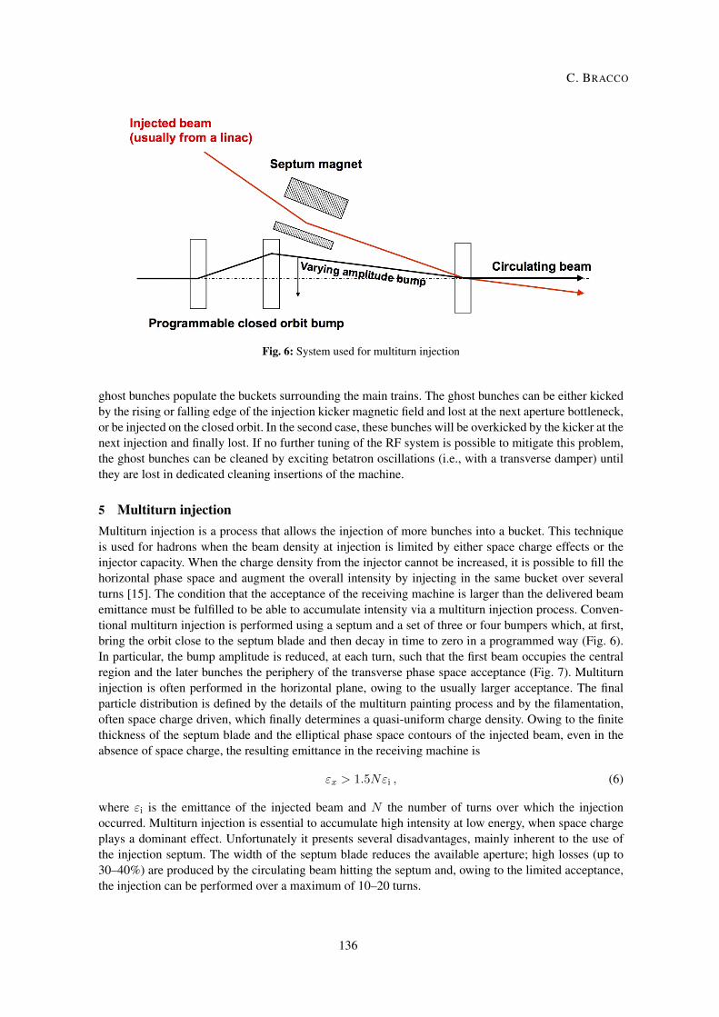
Fig. 6: System used for multiturn injection
ghost bunches populate the buckets surrounding the main trains. The ghost bunches can be either kickedby the rising or falling edge of the injection kicker magnetic field and lost at the next aperture bottleneck,or be injected on the closed orbit. In the second case, these bunches will be overkicked by the kicker at thenext injection and finally lost. If no further tuning of the RF system is possible to mitigate this problem,the ghost bunches can be cleaned by exciting betatron oscillations (i.e., with a transverse damper) untilthey are lost in dedicated cleaning insertions of the machine.
5 Multiturn injectionMultiturn injection is a process that allows the injection of more bunches into a bucket. This techniqueis used for hadrons when the beam density at injection is limited by either space charge effects or theinjector capacity. When the charge density from the injector cannot be increased, it is possible to fill thehorizontal phase space and augment the overall intensity by injecting in the same bucket over severalturns [15]. The condition that the acceptance of the receiving machine is larger than the delivered beamemittance must be fulfilled to be able to accumulate intensity via a multiturn injection process. Conven-tional multiturn injection is performed using a septum and a set of three or four bumpers which, at first,bring the orbit close to the septum blade and then decay in time to zero in a programmed way (Fig. 6).In particular, the bump amplitude is reduced, at each turn, such that the first beam occupies the centralregion and the later bunches the periphery of the transverse phase space acceptance (Fig. 7). Multiturninjection is often performed in the horizontal plane, owing to the usually larger acceptance. The finalparticle distribution is defined by the details of the multiturn painting process and by the filamentation,often space charge driven, which finally determines a quasi-uniform charge density. Owing to the finitethickness of the septum blade and the elliptical phase space contours of the injected beam, even in theabsence of space charge, the resulting emittance in the receiving machine is
"x > 1.5N"i , (6)
where "i is the emittance of the injected beam and N the number of turns over which the injectionoccurred. Multiturn injection is essential to accumulate high intensity at low energy, when space chargeplays a dominant effect. Unfortunately it presents several disadvantages, mainly inherent to the use ofthe injection septum. The width of the septum blade reduces the available aperture; high losses (up to30–40%) are produced by the circulating beam hitting the septum and, owing to the limited acceptance,the injection can be performed over a maximum of 10–20 turns.
6
C. BRACCO
136
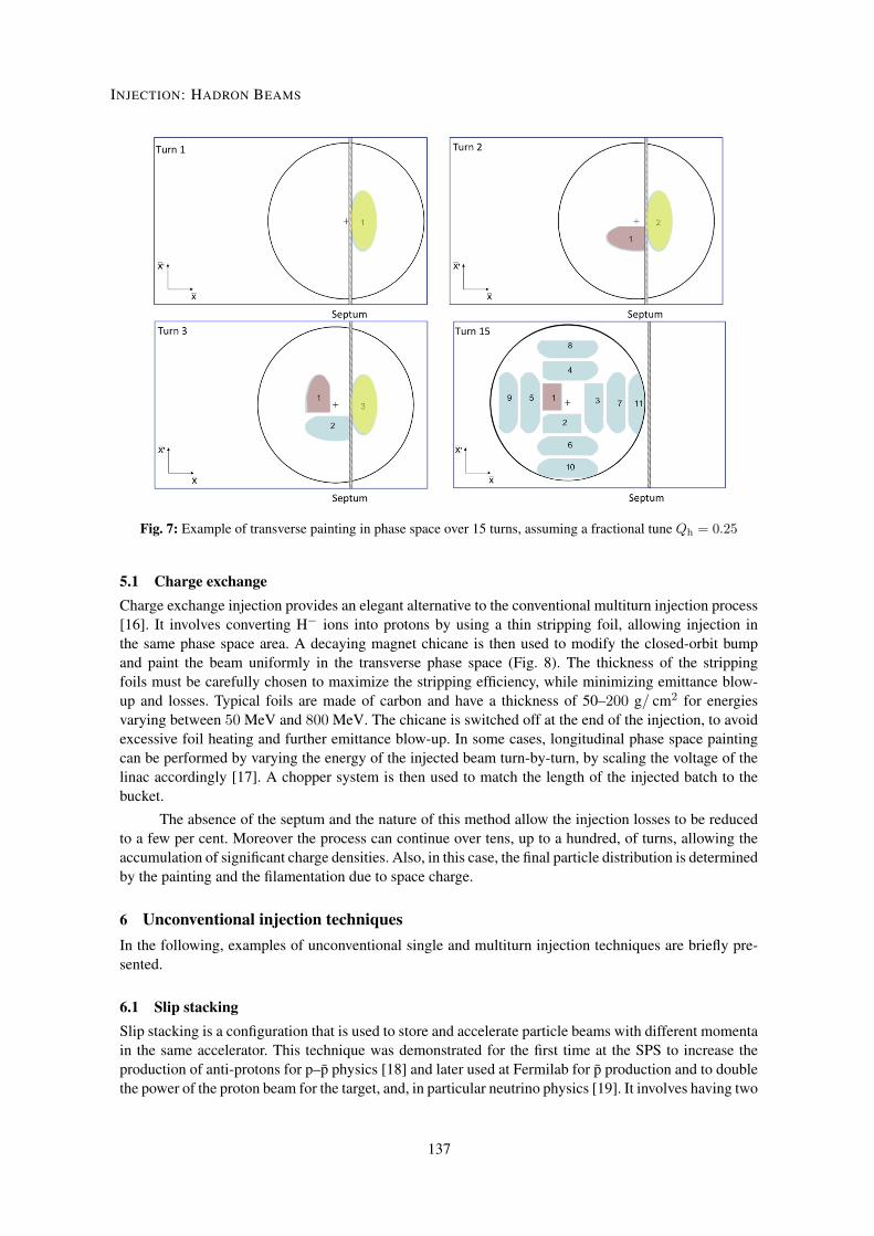
Fig. 7: Example of transverse painting in phase space over 15 turns, assuming a fractional tune Qh = 0.25
5.1 Charge exchangeCharge exchange injection provides an elegant alternative to the conventional multiturn injection process[16]. It involves converting H� ions into protons by using a thin stripping foil, allowing injection inthe same phase space area. A decaying magnet chicane is then used to modify the closed-orbit bumpand paint the beam uniformly in the transverse phase space (Fig. 8). The thickness of the strippingfoils must be carefully chosen to maximize the stripping efficiency, while minimizing emittance blow-up and losses. Typical foils are made of carbon and have a thickness of 50–200 g/ cm2 for energiesvarying between 50 MeV and 800 MeV. The chicane is switched off at the end of the injection, to avoidexcessive foil heating and further emittance blow-up. In some cases, longitudinal phase space paintingcan be performed by varying the energy of the injected beam turn-by-turn, by scaling the voltage of thelinac accordingly [17]. A chopper system is then used to match the length of the injected batch to thebucket.
The absence of the septum and the nature of this method allow the injection losses to be reducedto a few per cent. Moreover the process can continue over tens, up to a hundred, of turns, allowing theaccumulation of significant charge densities. Also, in this case, the final particle distribution is determinedby the painting and the filamentation due to space charge.
6 Unconventional injection techniquesIn the following, examples of unconventional single and multiturn injection techniques are briefly pre-sented.
6.1 Slip stackingSlip stacking is a configuration that is used to store and accelerate particle beams with different momentain the same accelerator. This technique was demonstrated for the first time at the SPS to increase theproduction of anti-protons for p–p̄ physics [18] and later used at Fermilab for p̄ production and to doublethe power of the proton beam for the target, and, in particular neutrino physics [19]. It involves having two
7
INJECTION: HADRON BEAMS
137
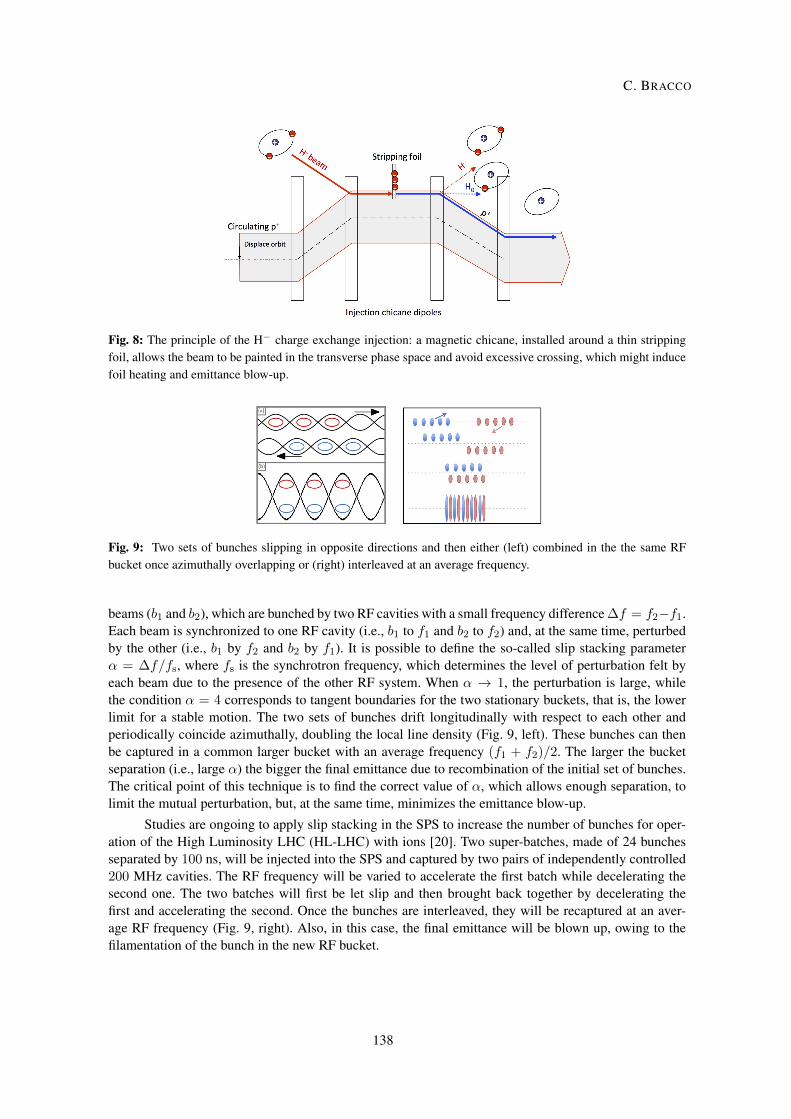
Fig. 8: The principle of the H� charge exchange injection: a magnetic chicane, installed around a thin strippingfoil, allows the beam to be painted in the transverse phase space and avoid excessive crossing, which might inducefoil heating and emittance blow-up.
Fig. 9: Two sets of bunches slipping in opposite directions and then either (left) combined in the the same RFbucket once azimuthally overlapping or (right) interleaved at an average frequency.
beams (b1 and b2), which are bunched by two RF cavities with a small frequency difference �f = f2�f1.Each beam is synchronized to one RF cavity (i.e., b1 to f1 and b2 to f2) and, at the same time, perturbedby the other (i.e., b1 by f2 and b2 by f1). It is possible to define the so-called slip stacking parameter↵ = �f/fs, where fs is the synchrotron frequency, which determines the level of perturbation felt byeach beam due to the presence of the other RF system. When ↵ ! 1, the perturbation is large, whilethe condition ↵ = 4 corresponds to tangent boundaries for the two stationary buckets, that is, the lowerlimit for a stable motion. The two sets of bunches drift longitudinally with respect to each other andperiodically coincide azimuthally, doubling the local line density (Fig. 9, left). These bunches can thenbe captured in a common larger bucket with an average frequency (f1 + f2)/2. The larger the bucketseparation (i.e., large ↵) the bigger the final emittance due to recombination of the initial set of bunches.The critical point of this technique is to find the correct value of ↵, which allows enough separation, tolimit the mutual perturbation, but, at the same time, minimizes the emittance blow-up.
Studies are ongoing to apply slip stacking in the SPS to increase the number of bunches for oper-ation of the High Luminosity LHC (HL-LHC) with ions [20]. Two super-batches, made of 24 bunchesseparated by 100 ns, will be injected into the SPS and captured by two pairs of independently controlled200 MHz cavities. The RF frequency will be varied to accelerate the first batch while decelerating thesecond one. The two batches will first be let slip and then brought back together by decelerating thefirst and accelerating the second. Once the bunches are interleaved, they will be recaptured at an aver-age RF frequency (Fig. 9, right). Also, in this case, the final emittance will be blown up, owing to thefilamentation of the bunch in the new RF bucket.
8
C. BRACCO
138
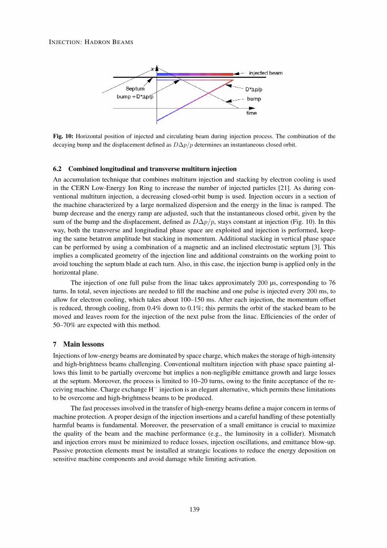
Fig. 10: Horizontal position of injected and circulating beam during injection process. The combination of thedecaying bump and the displacement defined as D�p/p determines an instantaneous closed orbit.
6.2 Combined longitudinal and transverse multiturn injectionAn accumulation technique that combines multiturn injection and stacking by electron cooling is usedin the CERN Low-Energy Ion Ring to increase the number of injected particles [21]. As during con-ventional multiturn injection, a decreasing closed-orbit bump is used. Injection occurs in a section ofthe machine characterized by a large normalized dispersion and the energy in the linac is ramped. Thebump decrease and the energy ramp are adjusted, such that the instantaneous closed orbit, given by thesum of the bump and the displacement, defined as D�p/p, stays constant at injection (Fig. 10). In thisway, both the transverse and longitudinal phase space are exploited and injection is performed, keep-ing the same betatron amplitude but stacking in momentum. Additional stacking in vertical phase spacecan be performed by using a combination of a magnetic and an inclined electrostatic septum [3]. Thisimplies a complicated geometry of the injection line and additional constraints on the working point toavoid touching the septum blade at each turn. Also, in this case, the injection bump is applied only in thehorizontal plane.
The injection of one full pulse from the linac takes approximately 200 µs, corresponding to 76turns. In total, seven injections are needed to fill the machine and one pulse is injected every 200 ms, toallow for electron cooling, which takes about 100–150 ms. After each injection, the momentum offsetis reduced, through cooling, from 0.4% down to 0.1%; this permits the orbit of the stacked beam to bemoved and leaves room for the injection of the next pulse from the linac. Efficiencies of the order of50–70% are expected with this method.
7 Main lessonsInjections of low-energy beams are dominated by space charge, which makes the storage of high-intensityand high-brightness beams challenging. Conventional multiturn injection with phase space painting al-lows this limit to be partially overcome but implies a non-negligible emittance growth and large lossesat the septum. Moreover, the process is limited to 10–20 turns, owing to the finite acceptance of the re-ceiving machine. Charge exchange H� injection is an elegant alternative, which permits these limitationsto be overcome and high-brightness beams to be produced.
The fast processes involved in the transfer of high-energy beams define a major concern in terms ofmachine protection. A proper design of the injection insertions and a careful handling of these potentiallyharmful beams is fundamental. Moreover, the preservation of a small emittance is crucial to maximizethe quality of the beam and the machine performance (e.g., the luminosity in a collider). Mismatchand injection errors must be minimized to reduce losses, injection oscillations, and emittance blow-up.Passive protection elements must be installed at strategic locations to reduce the energy deposition onsensitive machine components and avoid damage while limiting activation.
9
INJECTION: HADRON BEAMS
139
AcknowledgementsSpecial thanks to M.J. Barnes, W. Bartmann, M. Fraser, B. Goddard, and V. Kain for their inputs, thefruitful exchange of information, and stimulating discussions.
References[1] D.A. Edwards and M.J. Syphere, in An Introduction to the Physics of High Energy Accelerators,
(Wiley, New York, 1993), Chap. 6, pp. 172–186, https://doi.org/10.1002/9783527617272.[2] F. Tecker, Review of longitudinal beam dynamics, these proceedings.[3] M. Paraliev, Septa I and Septa II, these proceedings.[4] M.J. Barnes, Kicker systems. Part 1: introduction and hardware, these proceedings.[5] W. Bartmann, Transfer line design, matching, and design tools I, these proceedings.[6] V. Kain, Emittance, these proceedings.[7] W. Bartmann, Transfer line design, matching, and design tools II, these proceedings.[8] J.B. Jeanneret and R. Ostojic, Geometrical acceptance in LHC Version 5.0, LHC project note 111,
1997.[9] V. Kain, Machine protection and beam quality during the LHC injection process, Ph.D. thesis,
Technische Universität Wien, 2005, CERN-THESIS-2005-047.[10] W. Bartmann et al., Beam transfer to the FCC-hh collider from a 3.3 TeV booster in the LHC tunnel,
Proc. IPAC2015, Richmond, VA, USA.[11] M. Barnes, Kicker systems part 2, hardware: existing and future, these proceedings.[12] W. Bartmann et al., LHC injection and extraction losses, Proc. Evian Workshop, 2010.[13] O. Stein et al., Investigation of injection losses at the Large Hadron Collider with diamond based
particle detectors, Proc. IPAC2016, Busan, 2016.[14] L. Drösdal et al., SPS transverse beam scraping and LHC injection losses, Proc. IPAC 2012, New
Orleans, LA, 2012.[15] C. Prior, Ring injection for high intensity accelerators, CAS on High Power Hadron Machines,
Bilbao, 2011.[16] C. Bracco, Phase space painting and H� stripping injection, these proceedings.[17] V. Forte, Performance of the CERN PSB at 160 MeV with H� charge exchange injection, Ph.D.
thesis, CERN and Université Blaise Pascal, 2016.[18] D. Boussard and Y. Mizumachi, IEEE Trans. Nucl. Sci. NS-26 (1979) 3623,
https://doi.org/10.1109/TNS.1979.4330122.[19] J. Eldred and R. Zwaska, Slip-stacking dynamics and the 20 Hz booster, Fermilab-conf-14-565-
APC, Batavia, IL, 2015.[20] T. Argyroupoulos, Slip stacking in the SPS (mode of operation with beam, simulations, scheduled
tests and implementation), LIU Day, 2014.[21] C. Carli et al., Combined longitudinal and transverse multi-turn injection in a heavy ion accumu-
lator, Proc. PAC 1997, Vancouver, 1997.
10
C. BRACCO
140