µimu series...
TRANSCRIPT

MEMSENSE
www.memsense.com
888.668.8743
Information provided in this document is believed to be accurate, however it is not guaranteed.
MEMSense reserves the right to change product specifications at anytime without notice
µIMU
Micro Inertial Measurement Unit
Series Documentation Document: DN00009 Revision 2.2
May 2006

MEMSENSE
Table of Contents
1 Introduction............................................................................................................................... 3
1.1 The µIMU Micro Inertial Measurement Unit ................................................................... 3 2 Hardware .................................................................................................................................. 5
2.1 Connections ................................................................................................................... 5 2.2 Pin Function Description ................................................................................................ 5 2.3 RS422 Connection Description ...................................................................................... 5
3 Firmware................................................................................................................................... 6 3.1 Commands ..................................................................................................................... 6 3.2 Sample Format............................................................................................................... 6
4 Operation.................................................................................................................................. 8 4.1 Measurements................................................................................................................ 8 4.2 Coordinate System......................................................................................................... 9
5 Appendix A ............................................................................................................................. 10 5.1 Part Numbering ............................................................................................................ 10 5.2 Specifications ............................................................................................................... 11 Terms and Conditions, Warranty............................................................................................ 12
MEMSENSE
Document # DN00009 Rev 2.2 Page 3 of 12
1 Introduction
1.1 The µIMU Micro Inertial Measurement Unit
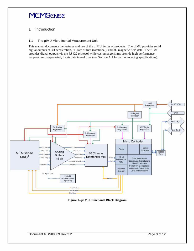
This manual documents the features and use of the µIMU Series of products. The µIMU provides serial digital outputs of 3D acceleration, 3D rate of turn (rotational), and 3D magnetic field data. The µIMU provides digital outputs via the RS422 protocol while custom algorithms provide high performance, temperature compensated, 3 axis data in real time (see Section A.1 for part numbering specifications).
Figure 1– μIMU Functional Block Diagram

MEMSENSE
Document # DN00009 Rev 2.2 Page 4 of 12
The µIMU is available in a custom package measuring 2.276 in. diameter × 0.956 in. height with front and back mounting options as shown in Figure 2.
Figure 2 – Front mount (dimensions in mils unless noted)
MEMSENSE
Document # DN00009 Rev 2.2 Page 5 of 12
2 Hardware
2.1 Connections
The µIMU interface connector is a Hirose HR-30 series miniature waterproof plastic connector. This connector provides excellent protection against the environment, as well as an IP67 protection rating. In addition, it contains a built-in lock/release mechanism, is lightweight and corrosion resistant.
The µIMU does not ship with a cable; the user must provide a cable with adequate shielding to provide for EMI protection, and configured to match the pin description as given in Section 2.2.
2.2 Pin Function Description
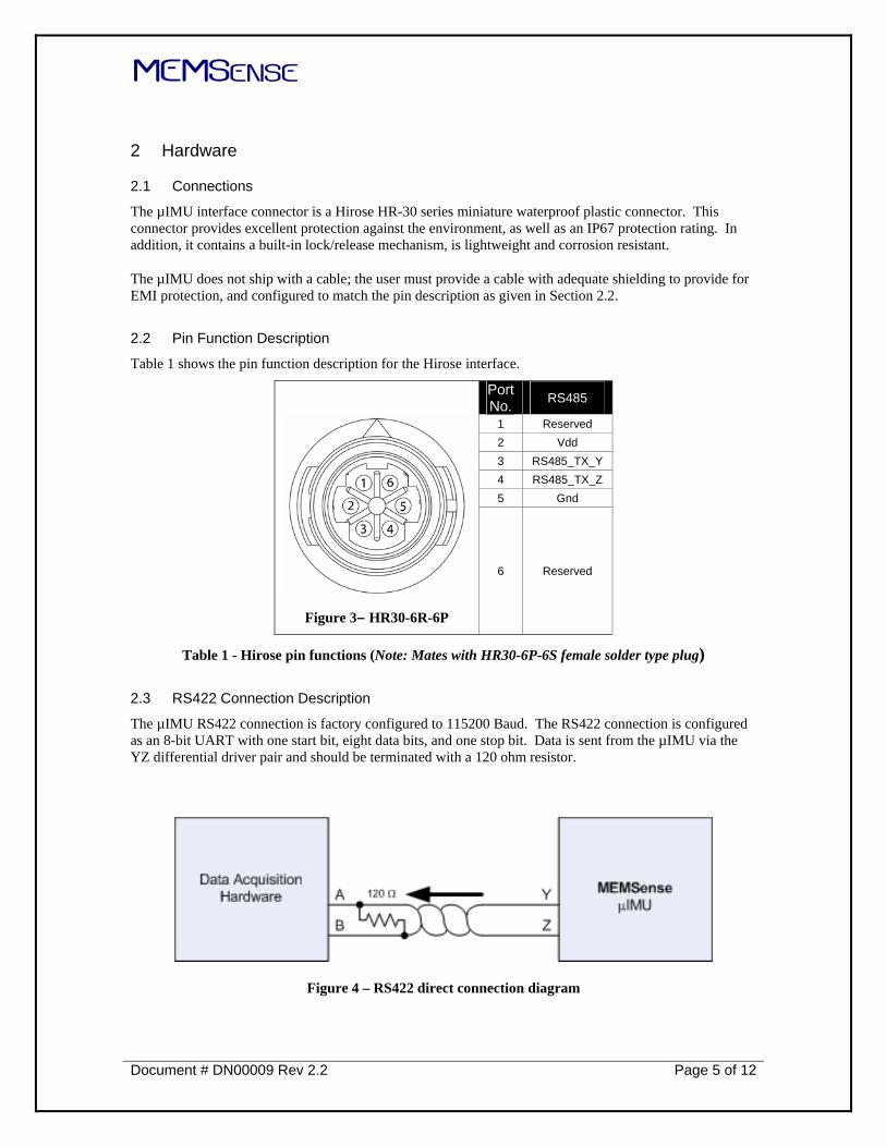
Table 1 shows the pin function description for the Hirose interface.
Port No. RS485
1 Reserved 2 Vdd 3 RS485_TX_Y 4 RS485_TX_Z 5 Gnd
Figure 3– HR30-6R-6P
6 Reserved
Table 1 - Hirose pin functions (Note: Mates with HR30-6P-6S female solder type plug)
2.3 RS422 Connection Description
The µIMU RS422 connection is factory configured to 115200 Baud. The RS422 connection is configured as an 8-bit UART with one start bit, eight data bits, and one stop bit. Data is sent from the µIMU via the YZ differential driver pair and should be terminated with a 120 ohm resistor.
Figure 4 – RS422 direct connection diagram

MEMSENSE
Document # DN00009 Rev 2.2 Page 6 of 12
3 Firmware
3.1 Commands
The µIMU does not currently offer a command structure or API that allows modification of device characteristics at runtime.
3.2 Sample Format
The µIMU will begin transmitting data once power is applied to the device. Data samples are formatted as shown in Tables 2 and 3. Each data channel is represented by a signed (2’s complement) 16-bit integer that must be converted to its corresponding engineering unit before use (see Section 4.1). An individual data packet is collectively referred to as a sample.
Byte Element 0 Synchronization byte (FF) 1 Synchronization byte (FF) 2 Synchronization byte (FF) 3 Synchronization byte (FF) 4 Message size 5 Device ID 6 Message ID
7-12 Reserved 13 Gyro X (MSB) 14 Gyro X (LSB) 15 Gyro Y (MSB) 16 Gyro Y (LSB) 17 Gyro Z (MSB) 18 Gyro Z (LSB) 19 Accelerometer X (2/5g) (MSB) 20 Accelerometer X (2/5g) (LSB) 21 Accelerometer Y (2/5g) (MSB) 22 Accelerometer Y (2/5g) (LSB) 23 Accelerometer Z (2/5g) (MSB) 24 Accelerometer Z (2/5g) (LSB) 25 Magnetometer X (MSB) 26 Magnetometer X (LSB) 27 Magnetometer Y (MSB) 28 Magnetometer Y (LSB) 29 Magnetometer Z (MSB) 30 Magnetometer Z (LSB) 31 8-bit Checksum
Table 2 - Sample byte order/format
Byte Element 0 Synchronization byte (FF) 1 Synchronization byte (FF) 2 Synchronization byte (FF) 3 Synchronization byte (FF) 4 Message size 5 Device ID 6 Message ID
7-12 Reserved 13 Gyro X (MSB) 14 Gyro X (LSB) 15 Gyro Y (MSB) 16 Gyro Y (LSB) 17 Gyro Z (MSB) 18 Gyro Z (LSB) 19 Accelerometer X (2/5g) (MSB) 20 Accelerometer X (2/5g) (LSB) 21 Accelerometer Y (2/5g) (MSB) 22 Accelerometer Y (2/5g) (LSB) 23 Accelerometer Z (2/5g) (MSB) 24 Accelerometer Z (2/5g) (LSB) 25 Magnetometer X (MSB) 26 Magnetometer X (LSB) 27 Magnetometer Y (MSB) 28 Magnetometer Y (LSB) 29 Magnetometer Z (MSB) 30 Magnetometer Z (LSB) 31 Accelerometer X (35/50g) (MSB) 32 Accelerometer X (35/50g) (LSB) 33 Accelerometer Y (35/50g) (MSB) 34 Accelerometer Y (35/50g) (LSB) 35 8-bit Checksum
Table 3 - Sample byte/order format including optional high g X/Y accelerometer

MEMSENSE
Document # DN00009 Rev 2.2 Page 7 of 12
Graphically, the sample has the format shown in Figure 5:
Figure 5 - Sample structure
All samples begin with four (4) synchronization bytes, where each byte is encoded with FF hex. Synchronization bytes aid in the identification of the beginning of samples as they arrive from the device. There are two cases in which synchronization is necessary: 1) initial synchronization of data once the device is powered and 2) re-synchronization if data is lost/discarded or errors are encountered. The complete structure of a sample is as follows (Note: all byte offsets are zero (0) based):
1. Synchronization bytes: bytes 0-3 with each byte encoded as FF hex. 2. Packet size: size, in bytes, of entire data packet, including complete header. 3. Device ID 4. Message ID: type of message. Currently, only data messages are transmitted by the device with
MID 0x14 hex (20 decimal). 5. Reserved bytes: six (6) bytes are reserved for internal/future use. 6. Payload: payload always starts at byte 13. The payload size can be calculated as follows:
payload_size = message_size – 13(header) – 1(checksum)
7. Checksum byte: 8-bit checksum byte. a. Sum sample contents (header + payload). DO NOT include the checksum byte. b. The summed value should equal the checksum if the message is valid. c. Note: If greater precision (larger than 8-bit) addition is used to calculate the checksum,
the checksum will be the remainder of a divide by 256.

MEMSENSE
Document # DN00009 Rev 2.2 Page 8 of 12
4 Operation
4.1 Measurements
Accelerometer, gyro and magnetometer data is temperature compensated on the nIMU. The payload element of the data packet contains accelerometer, gyro and magnetometer samples, which must be converted to values that represent usable data (e.g. rotational rate, G-force, gauss). The data is transmitted as signed (2’s complement) 16-bit integers. The following function must be used for conversion of sample values:
Equation 1:
⎟⎟⎟⎟
⎠
⎞
⎜⎜⎜⎜
⎝
⎛ ××=
32768
1.52
gedevice_ran
d_valueraw_payloaresult
where result is the converted value in the appropriate units (e.g. deg/sec), raw_payload_value is the raw component-specific value from the payload (e.g. accelerometer X), and device_range is the maximum possible range for the component (e.g. ±2 G accelerometer). Candidate ranges are as shown in Table 4 (NOTE: you must use the ranges specific to the device you have purchased). For example, if you have purchased a ±300 deg/s, ±2 G nIMU, the corresponding equations for the X component would be:
⎟⎟⎟⎟
⎠
⎞
⎜⎜⎜⎜
⎝
⎛ ××=
32768
1.52
600
d_value_x raw_payloavalue_x
⎟⎟⎟⎟
⎠
⎞
⎜⎜⎜⎜
⎝
⎛ ××=
32768
1.524
d_value_xraw_payloavalue_x
where raw_payload_value_x is taken from the sample payload corresponding to the x-components of the gyro and accelerometer, respectively. The resulting values have units of degrees/sec and G’s, respectively.
Component Resulting Units Range Gyro Degrees/sec ±300/±1200 Accelerometer G (9.8 m/s2) ±2/±5 Magnetometer Gauss ±1.9
Table 4 - Sensor dynamic ranges

MEMSENSE
Document # DN00009 Rev 2.2 Page 9 of 12
4.2 Coordinate System
The accelerometers produce a positive output proportional to the inertial resultant of the μIMU body acceleration. The gyros output a positive rate when the μIMU experiences a counterclockwise rotation about the positive acceleration axis. The coordinate system of the device is as shown in Figure 6.
Figure 6 - µIMU coordinate system

MEMSENSE
Document # DN00009 Rev 2.2 Page 10 of 12
5 Appendix A
5.1 Part Numbering
Part Accel.(g) Angular Rate (°/s) Bandwidth (Hz.) Optional Accel. (g)
IM02-0300C050A00 ±2 ±300 50 None IM02-0300C050A35 ±2 ±300 50 ±35 IM02-0300C050A50 ±2 ±300 50 ±50 IM02-1200C050A00 ±2 ±1200 50 None IM02-1200C050A35 ±2 ±1200 50 ±35 IM02-1200C050A50 ±2 ±1200 50 ±50 IM05-0300C050A00 ±5 ±300 50 None IM05-0300C050A35 ±5 ±300 50 ±35 IM05-0300C050A50 ±5 ±300 50 ±50 IM05-1200C050A00 ±5 ±1200 50 None IM05-1200C050A35 ±5 ±1200 50 ±35 IM05-1200C050A50 ±5 ±1200 50 ±50

MEMSENSE
Document # DN00009 Rev 2.2 Page 11 of 12
5.2 Specifications
PARAMETER SPECIFICATION UNITS CONDITIONS
Operational Requirements Operating Input Voltage 9.0 to 13.0 VDC unregulated Supply Current 180 mA typical Power Supply Rejection 60 db 5.4 to 9.0 volts Alignment Error ±1 % Mass 150 grams
Acceleration IM02 IM05 Dynamic Range ± 2 ± 5 g Offset ±30 ± 30 mg 0 to 70 °C Maximum Nonlinearity ± 0.4 (± 1.0 ) ± 0.4 (± 1.0 ) % of FS Typical (Maximum) Noise 5.0 (7.5) 5.0 (7.5) mg Typical (Maximum), 1 σ Digital Sensitivity 0.0000916 0.000229 g/bit See Equation 1 on page 9 Bandwidth 1 50 50 Hz -3dB point
Angular Rate -0300C050 -1200C050 Dynamic Range ± 300 ± 1200 °/s Offset +/-1 +/-1 °/s 0 to 70 °C Maximum Cross-Axis Sensitivity +/-1 +/-1 % Maximum Nonlinearity 0.1 0.1 % of FS Best fit straight line Noise 0.5 (0.95) 0.5 (0.95) °/s Typical (Maximum), 1 σ Digital Sensitivity 0.013733 0.054932 °/s/bit See Equation 1 on page 9 Bandwidth 1 50 50 Hz -3dB point
Magnetic Field Dynamic Range ±1.9 gauss Drift 2700 ppm/°C Nonlinearity 0.5 % of FS Best fit straight line Noise 5.6 x 10⁻³ gauss Typical (Maximum), 1 σ Digital Sensitivity 0.000087 gauss/bit See Equation 1 on page 9 Bandwidth1 50 Hz -3dB point
Optional Acceleration A35 A50 Axis X and Y X and Y Dynamic Range ± 35 ± 50 g Digital Sensitivity 0.001602 0.002288 g/bit See Equation 1 on page 9 Noise 1.0 1.0 mg/Hz½ Bandwidth1 50 50 Hz -3dB point
Absolute Maximum Ratings Acceleration Powered 2000 max g Any axis 0.5ms Input Voltage -0.3 (min) +12 (max) VDC Operating Temperature2 0 to +70 °C
Storage Temperature -55 to +125 °C Typical Values at 25°C, Vsupply = 5.6 VDC, 0 °/s, unless otherwise noted
1. Other bandwidth configurations are available upon request. 2. -40 to +85 °C operating temperature range is available.

MEMSENSE
Document # DN00009 Rev 2.2 Page 12 of 12
Terms and Conditions, Warranty
DEFINITIONS - As used herein: “Seller” means MEMSense LLC, 2693D Commerce Road, Rapid City, SD 57702. “Buyer” means the party purchasing Product(s) from the Seller. “Product” means all articles, materials, work or services offered by the Seller and described in the accompanying quotation, acknowledgement, invoice, or other Seller form. “Order” means any purchase Order or contract issued by the Buyer for Products provided by the Seller.
WARRANTY - Seller warrants that the Products will be free from defects in material and workmanship and conform in all material respects to their applicable specifications for a period of one (1) year from the date of delivery (“Warranty Period”), when operated under normal conditions and in accordance with their applicable specifications. For any breach of this warranty, Seller will, at its option and expense and as its sole obligation, and as Buyer’s exclusive remedy, repair or replace any defective Product returned to Seller during the Warranty Period, provided that an examination by Seller discloses to Seller’s reasonable satisfaction that a defect is covered by this warranty. This warranty does not apply to any Products that have been (i) subject to misuse, neglect, or abuse, (ii) improperly installed or maintained, or (iii) repaired or altered by anyone other than Seller. The warranty period for Products repaired or replaced under this warranty shall be limited to the components repaired or replaced and shall run for a period of one hundred and eighty (180) days from the date of delivery or the balance of the original one (1) year Warranty Period (excluding the time the Products were out of service and in Seller’s plant), whichever is longer. EXCEPT AS STATED IN THIS SECTION, SELLER MAKES NO WARRANTIES, EXPRESS OR IMPLIED, AND SPECIFICALLY DISCLAIMS ANY IMPLIED WARRANTIES OF FITNESS FOR A PARTICULAR PURPOSE, MERCHANTABILITY, TITLE, AND NON-INFRINGEMENT OF THIRD PARTY RIGHTS.
LIMITATION OF LIABILITIES - In no event shall Seller be liable to Buyer or any third party for consequential, indirect, punitive, special, or incidental damages (including but not limited to loss of profits) arising from or relating to the sale, delivery or use of the Products. Seller’s total cumulative liability under this Agreement to Buyer or any third party (including indemnity obligations), whether in contract or tort or otherwise, will not exceed the amount paid by Buyer to Seller for the Product sold hereunder giving rise to such liability.
DELAYS - Seller shall not be liable for delay in delivery or for failure to manufacture, due to causes beyond its reasonable control, including but not limited to acts of God, acts of any government, acts of civil or military authority, acts of Buyer, application of US Government priorities, Government delays in granting Export Licenses, fires, strikes, floods, war, terrorism, riot or civil commotion, delays in transportation, difficulty in obtaining necessary labor or materials. In the event of any such delay, date of delivery shall be extended for a period of time equal to that lost by reason of the delay.
TAXES - Prices do not include sales or excise tax, VAT, duties or other governmental charges resulting from this transaction or the manufacture, sale, ownership, possession, or use of the Products, all of which must be paid by Buyer. Buyer shall provide Seller a tax exemption certificate acceptable to the taxing authorities.
SHIPMENT - Title to all purchased material and risk of loss therefore is passed from Seller to Buyer at the time of shipment from Seller’s facility. Unless otherwise agreed upon in writing, all purchased material will be shipped uninsured. Seller may request partial shipment and invoice therefore.
EXPORT LICENSE – Buyer will comply with all applicable export and import control laws and regulations in its use of the Products and Buyer will not export or re-export the Products or any technical data or confidential information derived from or pertaining to the Products without all required United States and foreign government licenses.