implementation of can-interface and rtj heads-up...
TRANSCRIPT

Chalmers University of Technology
University of Gothenburg
Department of Signals and Systems
Gothenburg, Sweden, June 2012
Report No. EX032/2012
Implementation of CAN-interface and RTJ heads-up
display on an electric go-cart
Master of Science Thesis in the Programme Systems, Control and
Mechatronics
JONAS HENNING
JOHAN LOJANDER

The Author grants to Chalmers University of Technology and University of Gothenburg
the non-exclusive right to publish the Work electronically and in a non-commercial
purpose make it accessible on the Internet.
The Author warrants that he/she is the author to the Work, and warrants that the Work
does not contain text, pictures or other material that violates copyright law.
The Author shall, when transferring the rights of the Work to a third party (for example a
publisher or a company), acknowledge the third party about this agreement. If the Author
has signed a copyright agreement with a third party regarding the Work, the Author
warrants hereby that he/she has obtained any necessary permission from this third party to
let Chalmers University of Technology and University of Gothenburg store the Work
electronically and make it accessible on the Internet.
Implementation of CAN-interface and RTJ heads-up display on an electric go-cart
JONAS HENNING
JOHAN LOJANDER
© JONAS HENNING, June 2012.
© JOHAN LOJANDER, June 2012.
Examiner: PETTER FALKMAN
Chalmers University of Technology
University of Gothenburg
Department of Computer Science and Engineering
SE-412 96 Göteborg
Sweden
Telephone + 46 (0)31-772 1000
Cover:
A photo showing the electric go-cart platform controlled via a CAN cable.
Department of Signals and Systems
Gothenburg, Sweden, June 2012


Implementation of CAN interfaceand RTJ heads-up display on an
electric go-cart
Master of Science Thesis in the ProgrammeSystems, Control and Mechatronics
Jonas HenningJohan Lojander
June 4, 2012

Abstract
Today’s cars are filled with embedded systems making wayfor advanced safety techniques and comfort-increasing features.As a consequence, software complexity is taken to a completelynew level. To facilitate software development, automobile man-ufacturers have created an open standard called AUTOSAR. Itserves as an interface between hardware and software, easing thereuse of applications in ECUs.
Traditionally, real-time applications in automotive industryare developed in low-level languages as C, but with growing com-plexity these systems tend to be hard to overview. As a reac-tion to this, a research project called CHARTER was started.It strives to introduce high-level languages like real-time Java(RTJ) and model driven development in critical embedded sys-tems.
This thesis continues the development of an electric go-cartby extending the software functionality with a heads-up display,a cruise controller and a Controller Area Network (CAN) inter-face for its motor controller.
By adding a CAN interface to the motor controller, it waspossible to instead connect the torque and brake pedals to theVehicle Master Control Unit (VMCU), and let this device de-mand an adequate torque from the motor controller via CAN.
Aligning with both AUTOSAR and CHARTER, the heads-up display and the cruise controller were developed as AU-TOSAR software components in RTJ. The heads-up display pro-vides information about the vehicle to the driver, such as speedand battery status. The driver may also activate the cruise con-troller and set several options, through the heads-up display.
The future of AUTOSAR looks promising. The advantagesof scalability and reusability outperform the overhead in imple-mentation. With RTJ for embedded systems still being in itscradle, performance issues persists. Furthermore, the difficultyto reach the hardware with RTJ occasionally forces the use ofJava Native Interface, decreasing the benefits of using Java in thefirst place. However, the object-oriented approach and the lowlearning threshold of Java are benefits worth taking into account.
i
Preface
This master’s thesis was written for Chalmers University of Technology,Goteborg, Sweden as part of the master program Systems, Control andMechatronics. The thesis was performed by Jonas Henning and Johan Lo-jander at QRTECH, Goteborg. Examiner and supervisor at Chalmers wasPetter Falkman at the Signals and Systems (S2) Department. Supervisorat QRTECH was Anders Runeson and Benneth Claesson. We would like tothank our supervisors at QRTECH and Petter Falkman for the dedicationand help in our project.
Throughout this report, the master’s thesis will be referred to as thethesis.
ii
Contents
1 Introduction 11.1 Background . . . . . . . . . . . . . . . . . . . . . . . . . . . . 1
1.1.1 About QRTECH . . . . . . . . . . . . . . . . . . . . . 11.1.2 Project description . . . . . . . . . . . . . . . . . . . . 1
1.1.2.1 Delimitation . . . . . . . . . . . . . . . . . . 41.1.2.2 The go-cart . . . . . . . . . . . . . . . . . . . 4
1.1.3 Related work . . . . . . . . . . . . . . . . . . . . . . . 51.1.3.1 AC-motor control . . . . . . . . . . . . . . . 51.1.3.2 In-vehicle infotainment demonstrator . . . . 6
2 Theory 72.1 AUTOSAR . . . . . . . . . . . . . . . . . . . . . . . . . . . . 7
2.1.1 BSW . . . . . . . . . . . . . . . . . . . . . . . . . . . . 82.1.2 RTE . . . . . . . . . . . . . . . . . . . . . . . . . . . . 82.1.3 Application layer . . . . . . . . . . . . . . . . . . . . . 8
2.2 CHARTER . . . . . . . . . . . . . . . . . . . . . . . . . . . . 82.3 Controller Area Network . . . . . . . . . . . . . . . . . . . . . 92.4 PID control . . . . . . . . . . . . . . . . . . . . . . . . . . . . 122.5 Hardware Specifications . . . . . . . . . . . . . . . . . . . . . 13
2.5.1 VMCU and BMU . . . . . . . . . . . . . . . . . . . . 132.5.2 Motor controller . . . . . . . . . . . . . . . . . . . . . 14
3 Method 153.1 The waterfall model . . . . . . . . . . . . . . . . . . . . . . . 153.2 Agile model . . . . . . . . . . . . . . . . . . . . . . . . . . . . 153.3 Working process . . . . . . . . . . . . . . . . . . . . . . . . . 163.4 Development Environments . . . . . . . . . . . . . . . . . . . 16
3.4.1 Eclipse Java IDE . . . . . . . . . . . . . . . . . . . . . 173.4.2 JamaicaVM . . . . . . . . . . . . . . . . . . . . . . . . 173.4.3 Code Composer Studio 5 . . . . . . . . . . . . . . . . 17
3.4.3.1 COM-configurator . . . . . . . . . . . . . . . 183.4.3.2 CANoe . . . . . . . . . . . . . . . . . . . . . 18
3.4.4 Test-bench . . . . . . . . . . . . . . . . . . . . . . . . 18
4 Implementation 214.1 Heads-up Display . . . . . . . . . . . . . . . . . . . . . . . . . 214.2 Cross-compilation for ARM with JamaicaVM . . . . . . . . . 23
4.2.1 Profiling . . . . . . . . . . . . . . . . . . . . . . . . . . 244.3 Motor controller and CAN interface . . . . . . . . . . . . . . 25
4.3.1 CAN bus performance . . . . . . . . . . . . . . . . . . 264.4 Cruise controller . . . . . . . . . . . . . . . . . . . . . . . . . 26
iii
5 Discussion and Conclusion 285.1 Discussion . . . . . . . . . . . . . . . . . . . . . . . . . . . . . 285.2 Conclusion . . . . . . . . . . . . . . . . . . . . . . . . . . . . 29
A Gantt chart 32
iv
Acronyms
Name Description
A/D Analog/Digital
ADC Analog (to) Digital Converter
AUTOSAR AUTomotive Open System ARchitecture
BMU Battery Management Unit
BSW Basic Software
CAN Controller Area Network
CHARTER Critical and High Assurance Requirements Transformed through Engineering Rigour
CRC Cyclic Redundancy Check
DLC Data Length Code
DSP Digital Signal Processor
DTC Diagnostic Trouble Code
ECU Electronic Control Unit
E/E Electrics/Electronics
EMU Engine Master Unit (?)
GUI Graphical User Interface
HUD Heads-Up Display
IDE Integrated Development Environment
JNI Java Native Interface
JML Java Modeling Language
JVM Java Runtime Environment
JVM Java Virtual Machine
OS Operating System
PID Proportional-integral-derivative
PWM Pulse-Width Modulation
RPM Revolutions per Minute
RTE Runtime Environment
RTJ Real Time Java
SoC State of Charge
SoH State of Health
SW-C Software Component
SysML Systems Modeling Language
UML Unified Modeling Language
VM Virtual Machine
VMCU Vehicle Master Control Unit
v

List of Figures
1 System description of the go-cart . . . . . . . . . . . . . . . . 22 The go-cart before it was rebuilt . . . . . . . . . . . . . . . . 53 AUTOSAR layered architecture . . . . . . . . . . . . . . . . . 74 CAN bus overview . . . . . . . . . . . . . . . . . . . . . . . . 105 The ARM-based VMCU board . . . . . . . . . . . . . . . . . 136 The Texas Instruments DSP . . . . . . . . . . . . . . . . . . . 147 The waterfall model. . . . . . . . . . . . . . . . . . . . . . . . 168 Illustrating the difference of how the garbage collector works
with Java and RTJ. . . . . . . . . . . . . . . . . . . . . . . . 179 CANoe, a CAN development and testing software tool . . . . 1910 The test bench set-up . . . . . . . . . . . . . . . . . . . . . . 2011 The different views of the heads-up display . . . . . . . . . . 2212 Driving profiles . . . . . . . . . . . . . . . . . . . . . . . . . . 2313 Cruise Controller block diagram . . . . . . . . . . . . . . . . . 26
vi

1 Introduction
Today’s electrification of cars provides a lot of opportunities. Cars are filledwith embedded systems making way for advanced safety techniques andcomfort-increasing features. As a result of this, software complexity is takento a completely new level. Traditionally, real-time applications in automo-tive industry are developed in low-level languages as C, but with growingcomplexity these systems tend to be hard to overview.
An ongoing project, named CHARTER (Critical and High AssuranceRequirements Transformed through Engineering Rigour), carried out byQRTECH and several other European companies and institutions, servesto use model driven development (e.g. JML/UML) and high-level languages(e.g. real-time Java) to develop software for embedded systems.
To take a leading position in this matter in the automotive industry ofthe future, QRTECH designed a master thesis serving to develop real-timeapplications in Java for their electric go-cart. The go-cart has been workedon during other previous masters’ theses carried out at QRTECH and servesas a platform for testing and evaluating new techniques, hardware as wellas software.
1.1 Background
This section describes the challenges of this project, delimitations of thethesis, a brief introduction to the thesis-requesting company QRTECH aswell as previous and related work.
1.1.1 About QRTECH
QRTECH is a product development company with services within softwareand electronics development. QRTECH also possesses long experience ofembedded systems in the automotive industry-dense city of Gothenburg.
For several years QRTECH has worked on an electric go-cart used as aplatform for testing automotive industry techniques such as electric motorcontrol, infotainment systems, battery management systems and, concerningthe thesis, drive-by-wire and real-time Java software development for criticalsystems.
1.1.2 Project description
The thesis will further develop the electric go-cart by implementing soft-ware functionality. The desired functions are: a heads-up display (HUD)presenting data and status about the vehicle, a cruise controller, an errorhandling mechanism and a CAN interface for the motor controller. Addi-tionally, the available motor controller needs to be adapted to align with thenew CAN interface developed in the thesis. Since this project is a part of
1
another project called CHARTER (section 2.2), real-time Java will be usedfor realisation of some software functionalities. In the scope of the thesisalso lies a general understanding of the complete system and how its partswork together.
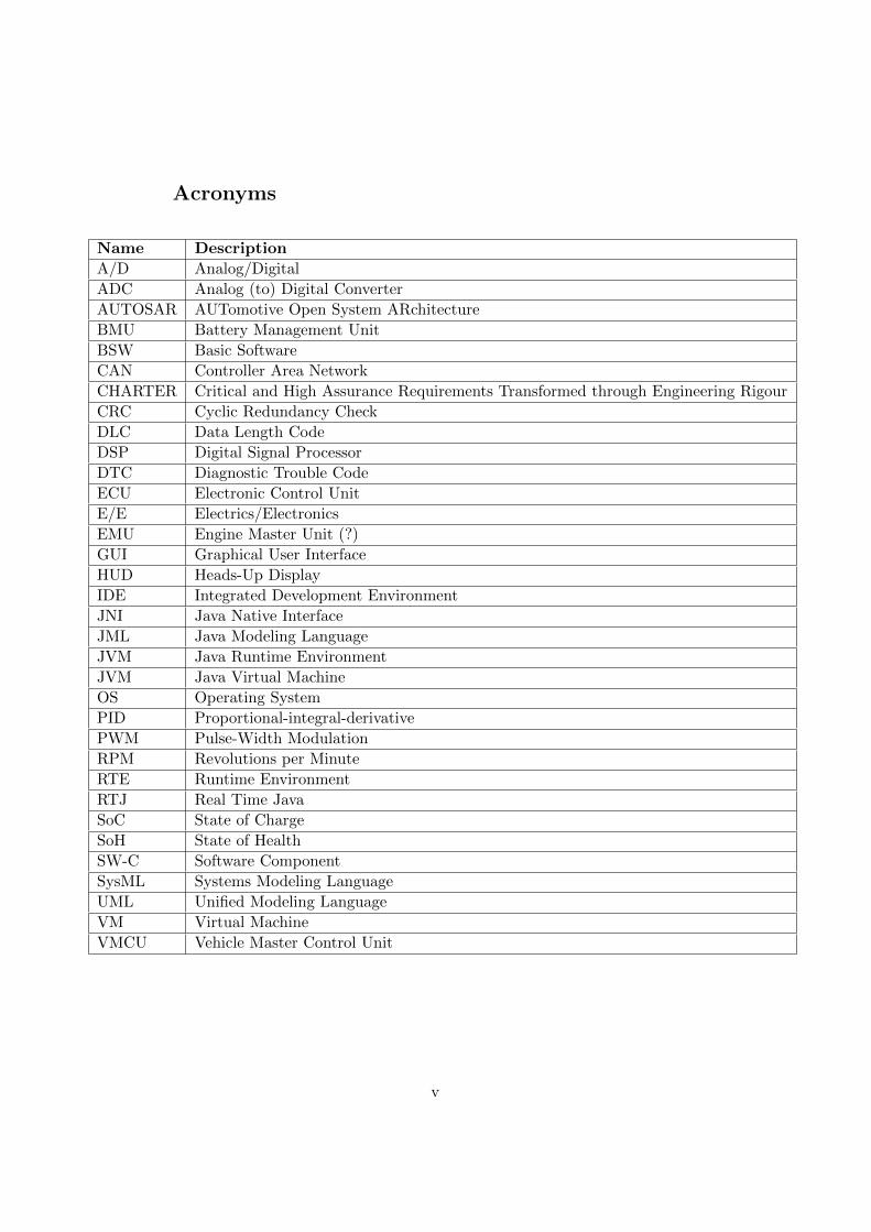
In Figure 1, an overview of the go-cart system is presented. Before thestart of the project, the pedals of the go-cart (Throttle and Brake in Figure1) were directly connected to the motor controller, affecting output torque ofthe AC-motor. For details, please refer to section 1.1.3.1. By the end of thethesis, the Vehicle Master Control Unit (VMCU) should request a torquefrom the motor controller via CAN, according to the pedals connected tothe VMCU, see Figure 1. At thesis start, CAN was physically available onthe motor controller, but unused. The thesis should design a CAN interfacefor the motor controller making it possible to request a torque via CAN.The CAN-network is also supposed to include a Battery Management Unit(BMU) responsible for features like measuring cell voltages and current drainas well as providing battery cell balancing functionality.
Motor controller(Inverter) BMU
Brake
VMCU
Throttle
Heads-updisplay
Motor
CAN
Figure 1: System description of the go-cart.
The CAN interface adaptation makes communication between the motorcontroller and the VMCU possible in both directions. By installing theVMCU and its display in the dashboard it can also serve as a heads-updisplay, presenting information such as speed, battery state of charge andengine temperature to the driver.
The design of the graphical user interface (GUI) of the heads-up displayis thus part of the thesis and it should display five different views presentinginformation as:
• Driving View
– Speed
– Revolutions per minute (RPM)
2

– Battery State of Charge (SoC)
– Temperature
– Average Speed
– Trip-meter
• Battery View
– Battery State of Charge (SoC)
– Battery State of Health (SoH)
– Voltage
– Current drain
– Individual Cell Voltage
– Battery balancing mode
• Diagnostics View
– Diagnostic Trouble Codes (DTC)
– Possibility to clear certain or all DTCs
• Properties View
– Driving mode selection (Normal, Eco, Sport)
– Charging activation/deactivation
– GUI-menu position (left/right)
• Demo View
– QRTECH presentation
Note that development of the BMU itself is not part of the thesis, eventhough information will be collected from the unit for presentation on theheads-up display.
A cruise controller maintaining a desired speed given by the driver willbe developed. The idea is to let the cruise controller create a virtual throttlepedal, sending an appropriate requested torque to the motor controller tomaintain a close to constant speed.
Creating error handling functions to detect and react to system malfunc-tion is also part of the thesis. The driver should be alerted of system errorsand be able to take stance to and clear these errors. Security measuresavoiding critical errors like brake dysfunction or the motor locking on fulltorque in case of a CAN failure will also be implemented.
3

1.1.2.1 Delimitation
The work is carried out at QRTECH in Kalleback, Gothenburg. Fo-cus is software development so hardware should be available and no changesintended. It might be necessary to do some measurements in order totest hardware or verify software results. There is no cost limit. Somecomplementary items might be purchased after approval of request. Thethesis starts the 23rd of January spanning to the 8th of June, i.e. a totalof 20 weeks. The final date may be postponed if necessary, but meetingdeadlines are wished-for. Desired date of the handover of the planningreport is early February, the oral presentation at end of May and thehandover of the final report early June.
To limit time requirement for studies of related work and the go-cartsystem overview, technical details of these were omitted.
The thesis incorporates work with the complete CAN interface on themotor controller. On the VMCU however, only the software componentsas the HUD and cruise controller are worked with. The lower AUTOSARlayers, mainly the basic software and the RTE-layer are performed by acolleague at QRTECH and are not part of the thesis. Some co-operation forintegrating the RTE-layer and the SW-Cs may however be needed.
Visual design of the heads-up display is secondary, focus is instead tech-nology level and a well-working CAN interface including error detection.
1.1.2.2 The go-cart
The QRTECH go-cart was originally a standard go-cart with a com-bustion engine. In 2010 it was rebuilt for electric drive as a part of amaster’s thesis in co-operation with Chalmers, where a Simulink model ofthe electric motor of the go-cart was derived.
The AC-motor controller is based on a Digital Signal Processor (DSP),which can be viewed in Figure 2 as the small red board close to the blackcables. The control algorithm was made as a previous master’s thesis atQRTECH, described in Section 1.1.3.1. The battery pack is based on a setof car batteries supplying the electric motor 48 volts. The motor drives therear axis with a constant gear ratio of 13:73. The throttle and brake pedalsare connected through wires to sliding potentiometers. The output voltagefrom the potentiometers is read by the motor controllers analog to digitalconverters (ADCs).
Furthermore, the go-cart is intended to be rebuilt by the end of thethesis. The Pb-batteries will be changed to a lighter lithium-ion batterypack, the heads-up display and BMU will be installed close to the batterypack. Also, a CAN bus interconnecting the VMCU, DSP and BMU will beadded, and the brake and throttle pedals are to be connected to the VMCU,
4

Figure 2: The go-cart before it was rebuilt. Notice the twisted CAN cableused to control the go-cart from the PC.
to support drive-by-wire functionality over CAN.
1.1.3 Related work
Since an insight of the complete system and how its parts works together wasdesired for in the thesis, this subsection explains previous projects relatedto the thesis.
1.1.3.1 AC-motor control
The previous master thesis carried out on the go-cart at QRTECHaimed to develop a motor control algorithm for the AC motor. The motortorque is controlled by a PID-regulator on the motor controller. By alteringthe duty cycle of the Pulse Width Modulation-signals (PWM) affecting themotor current, the motor torque is controlled. Since the motor output axisis directly connected to the rear axis (via fixed gears) the control algorithmis closely connected to the vehicle speed.
Extensive studies of the AC-motor control project have been performedin the thesis. Integration with the motor controller is crucial when mov-ing the pedals to the VMCU. Information in CAN frames received by themotor controller will serve as input to the AC-motor control algorithm. Fur-
5

thermore, the implementation of a cruise control algorithm relies upon theAC-motor controller for smooth speed control. No report of the master the-sis was available at the writing of the thesis, whereof the lack of reference.
1.1.3.2 In-vehicle infotainment demonstrator
The main purpose of Sanell’s and Samuelsson’s project was to exam-ine the possibility of using available hardware and software when developinginfotainment systems for automotive industry and investigate if it coulddeliver the same performance as custom, self-made systems. The benefit ofusing already existing hardware and software would be reducing costs.
The work carried out by Sanell and Samuelsson can be seen as the pre-decessor to the thesis and, naturally, has a lot of similarities. Both tryingto develop heads-up displays to present information to the driver on prede-fined hardware and operating systems. Sanell’s and Samuelsson’s heads-updisplay were created using QT (a framework for creating graphical userinterfaces) on a MeeGo Linux based system whereas the thesis runs theAngstrom distribution on slightly different hardware and with the GUI nowdeveloped in Java Swing. While the in-vehicle infotainment demonstratorthesis explored the possibilities of showing information provided via CANto the driver this thesis actually implements both CAN interface and HUD,on a live platform. (Hans Sanell and Goran Samuelsson, 2011)
6
2 Theory
The theory section describes the open automotive standard AUTOSAR andthe dominating communication protocol in vehicles, Controller Area Net-work. The in parallel on-going project CHARTER, serving to introducemodel driven development in embedded systems, is also considered.
2.1 AUTOSAR
The automotive industry is getting complex and diversified within the fieldof Electrics/Electronics (E/E) implementation. Therefore automobile man-ufacturers, suppliers and tool developers have developed an open standardcalled AUTOSAR, AUTomotive Open System ARchitecture. It is being de-veloped and established as an interface between hardware and software toease the reuse of applications and other software modules. AUTOSAR alsoimproves flexibility in case of software modifications and eases scalabilitywithin and across product lines, cutting costs as a result. (Adam Hulin andMarcus Johansson, 2011)
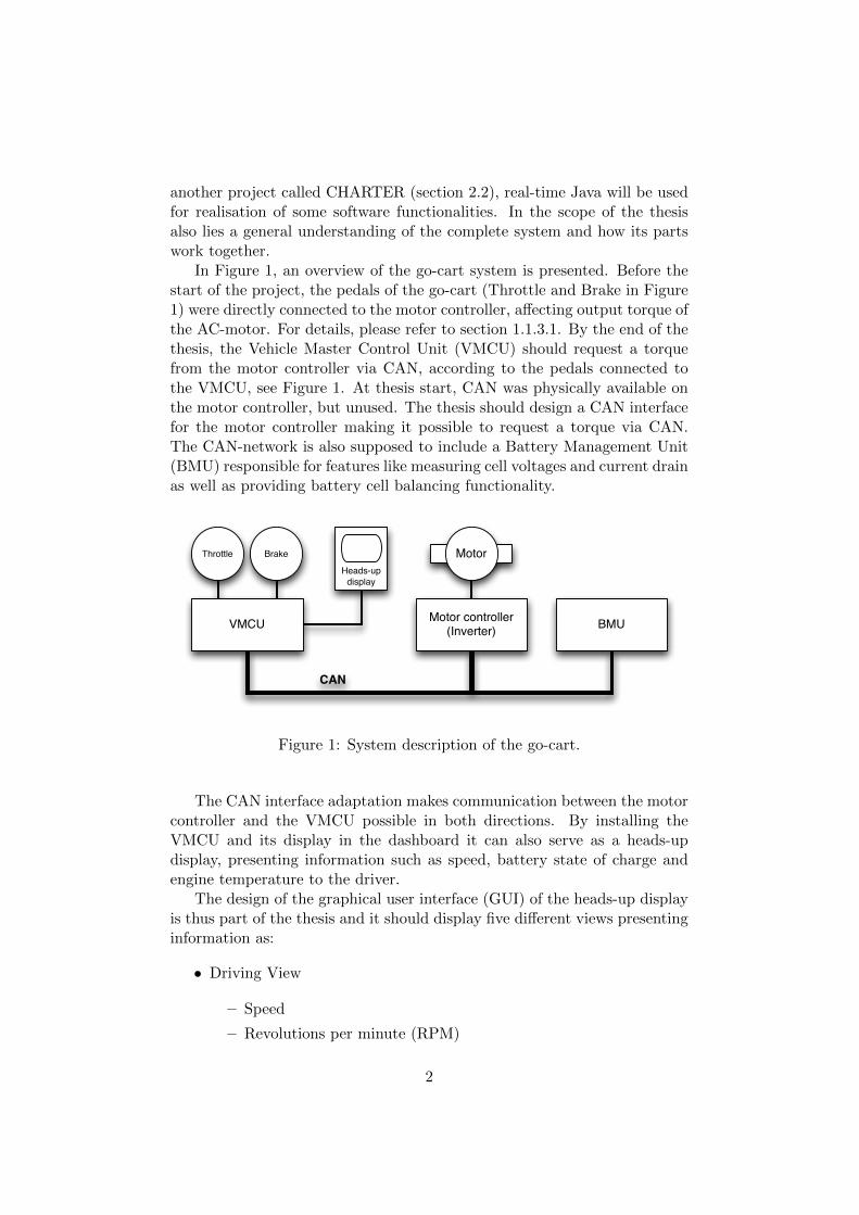
Figure 3: AUTOSAR software architecture including the three layers andthe important standardised interfaces. (Johan Elgered and Jesper Jansson,2012)
AUTOSAR consists of multiple layers, see Figure 3, the basic softwarelayer (BSW), the runtime environment (RTE) layer and the applicationslayer.
7

2.1.1 BSW
The lowest layer is called basic software, which consist of MicrocontrollerAbstration Layer, ECU Abstratcion Layer, Services Layer and ComplexDrivers. The Microcontroller Abstraction Layer receives calls from higherlevels and forward these calls in a standardised way to the hardware andperipherals. The BSW is the only layer with direct access to the micro-controller. The basic software layer also incorporates the operating systemand interfaces to the upper layer, called RTE. (AUTOSAR, 2012)
2.1.2 RTE
The RTE is the layer in between the BSW and the applications layer. TheRTE-layer makes communication in underlying layers transparent to thedeveloper programming software components. Since SW-Cs are dependenton the ECU hardware, the RTE has to be customised for the ECU on whichit runs. ECU-specific configuration therefore leads to that RTEs differentiatebetween different ECUs. (Johan Elgered and Jesper Jansson, 2012)
2.1.3 Application layer
The applications layer consists of multiple software components, often re-ferred to as SW-Cs. The SW-Cs comes in two types, application softwarecomponent type and sensor actuator type. The latter is software represent-ing a sensor or an actuator whereas the former provides actuators with inputby collecting sensor data. (AUTOSAR, 2012)
All actual functionality in the vehicle is developed in the software com-ponents. The purpose of the BSW and the RTE layers is simplifying andstandardising development of the software components, increasing reusabil-ity and modularity. These properties makes AUTOSAR cost saving sincedevelopment and testing effort for software components can be reduced.SW-Cs can be ported to other target platforms without spending time onadaptation to new environments (Joakim Plate and Peter Fridlund, 2011)
The modular concept of course has drawbacks, mainly performance issuesdue to increased processor and memory usage. Standardised software willalways take detours that single-purpose software can avoid. However, withtoday’s increased hardware performance this may be a price worth payingfor increased software reusability. (Joakim Plate and Peter Fridlund, 2011)
2.2 CHARTER
Embedded systems are traditionally developed in low-level languages likeC or Assembly as these gives the programmer good control of time criti-cal events. However, in big and complex systems the vast number of linesof code can make the system difficult to overview. Therefore a project
8

called CHARTER (Critical and High Assurance Requirements Transformedthrough Engineering Rigour) was started, striving to introduce high-levellanguages and model driven development in critical embedded systems andevaluate performance compared to traditional low-level languages.
QRTECH has good experience of time critical embedded systems, mainlydue to involvement in automotive industry, and the company’s role as aCHARTER project member is to implement code of high-level languages(especially real time Java) in critical embedded systems, in this case thego-cart.
CHARTER is a ARTEMIS Embedded Computing Systems Initiativeproject partnership between the European Commission, member states (UK,Sweden, Ireland, Netherlands, Germany) and ARTEMISI (a non-profit In-dustrial Association).
Partnership members except for QRTECH include universities likeChalmers Univeristy of Technology and Dundalk Institute of Technology,but also companies like Impronova (SWE), aicas (GER) and Atego (UK).(Alec Dorling, 2012)
2.3 Controller Area Network
Controller Area Network (CAN) is a multi-master broadcast serial bus de-fined by Bosch in the mid-80’s. It was initially intended for use in theautomotive industry and has been the dominating communication protocolin cars and trucks since the mid-90’s. Due to the low cost of CAN controllersit has also become popular in other fields such as industrial automation andequipment for the medical industry. (Computer Solutions Ltd, 2012)
A modern car contains about 50 electrical control units (ECU’s), eachone often responsible for one feature, for example engine control, airbags,cruise control, doors or mirror adjustment. Actuators and sensors are inturn often connected to the ECU’s. The CAN bus connects the ECU’s andprovides the possibility for the ECU’s to communicate with one another.CAN is particular in the sense that nodes are not predefined specific ad-dresses, instead the messages have identifiers. Nodes can therefore listen forspecific messages on the bus and ignore those which are not of interest tothe node. In the same manner, nodes transmit messages with different iden-tifiers depending on message content and receiver. The message identifieralso defines the messages priorities, where a lower identifier corresponds toa high priority and vice versa. (Joakim Plate and Peter Fridlund, 2011)
When the CAN bus is idle, any node on the bus is free to start transmit-ting. In the case of two nodes starting to send simultaneously, the highestprioritised message (with lowest numerical id) will win the arbitration andfulfil transmission whereas the message with lower priority will sense this,step back and wait for the bus to be free, allowing for the message to beresent after a predefined delay. (Joakim Plate and Peter Fridlund, 2011)
9

This built in prioritisation of messages is achieved using recessive anddominant bits, ’1’ being recessive and ’0’ being dominant. If the bus is idle(no one is sending) the bus is in it’s recessive state (high). If a node sendsa dominant ’0’-bit, it grounds the bus, drawing it down to ’0’. So, if adominant bit is sent on the same time as a recessive bit, the dominant bit isdisplayed on the bus. The node sending the recessive bit sees that the busis ’0’ even if it sent a ’1’, and a collision is detected. If all nodes have uniqueidentifiers, which is necessary, a single node remains as winner when a fullidentifier has been transmitted. This node now continues to send its data.(Joakim Plate and Peter Fridlund, 2011)
There are two CAN specifications, basic (standard) CAN and full (ex-tended) CAN. Basic CAN offers a maximum transfer speed of 250 kbit/sand an 11 bit message identifier whereas the full CAN is capable of 1 mbit/swith a 29 bit identifier. These transfer speeds are defined for 50 meter buslength. By lowering speed the bus length can be increased, for example 125kbit/s at around 500 meter extended CAN. There are a lot of possibilitieswhen choosing physical media for CAN, the most common being twisted pairon a 5V differential signal. The CAN-low (CANL, CAN-) holding -2.5V andCAN-high (CANH, CAN+) holding +2.5V. This makes the physical layerrobust even in noisy environments such as vehicles. The bus should be termi-nated with 120Ω-resistances in both ends between CAN-low and CAN-highto prevent interference due to reflections. A small CAN bus containing threenodes can be seen in Figure 4. (Robert Bosch GmbH, 2012)
CAN NodeMicrocontroller
CAN Controller
CAN Tranceiver
R
CAN NodeMicrocontroller
CAN Controller
CAN Tranceiver
CAN NodeMicrocontroller
CAN Controller
CAN Tranceiver
R
CANH
CANL
Figure 4: A CAN bus with the two differential signals CANL and CANH,terminated with 120Ω resistances.
As for the physical media, connector types are not yet formally specifiedand custom designs are common. However, the 9-pin D-sub connector with
10

the following pin-out, has become popular.
• pin2: CAN-low (CAN-)
• pin3: GND (Ground)
• pin7: CAN-high (CAN+)
• pin9: CAN V+ (Power)
CAN offers four different types of frames, remote frame, error frame,overload frame and data frame. The data frame comes in two formats, basicand extended. The extended data frame is the only one used in the thesisand its frame layout is showed in Table 1:
Name Bit-length Description
SOF 1 Start-of-frame.
ID part 1 11 First part of message identifier, also represents message priority
SRR 1 Recessive (0)
IDE 1 Identifier extension bit
ID part 2 18 Second part of message identifier, also represents message priority
RTR 1 Dominant (0) (see Remote Frame below)
Reserved bits 2 Reserved bits, dominant (0)
DLC 4 Data length code, number of bytes of data (0-8)
Data 0–64 Data to be transmitted (bytelength corresponds to DLC field)
CRC 15 Cyclic Redundancy Check, Checksum
CRC delimiter 1 Always (1)
ACK slot 1 Transmitter sends recessive (1), any receiver ACKs with dominant (0)
ACK delimiter 1 Must be recessive (1)
EOF 7 End-of-frame, must be recessive (1)
Table 1: The layout of the CAN data frame.
Normally CAN frames are sent cyclically, messages can for example besent every 10 or 100 ms. Using this manner, errors can be detected. If aspecific message stops arriving, nodes will realise there is an error occurrence,making adequate actions. Also, bus overload can be avoided since bus loadis kept close-to constant if all messages ”always” are sent with a specificcycle time. CAN buses in automotive industry often have a bus load around70-80%.
CAN is well suited in vehicles for a lot of reasons. It is cheap and reliablein harsh and noisy environments. Being message based also favours CANwhen deciding for a network type for the automotive industry, since certaindata often is relevant for several nodes in the vehicle and data consistency
11

is important. CAN also has the ability to automatically drop faulty nodeson the bus to prevent these from bringing the network down. This faultconfinement ensures bandwidth for critical transmissions. (Corrigan, 2002,revised 2008)
Another commonly used construction of CAN frames in the automotiveindustry is the usage of the update bit. It is a single bit which is set to 1if the corresponding signal has been updated, assuring the receiver that thetransmitter successfully managed to send a new updated value of the signalin the most recent frame. (Joakim Plate and Peter Fridlund, 2011)
2.4 PID control
The Proportional-Integral-Derivative controller (PID controller) is a com-monly used controlling mechanism within industry and other control inten-sive environments. It uses an error (calculated as the difference between adefined setpoint value and the output signal from the process) to adjust theinput signal to the process which it controls. The PID-controller is knownas three-term control since it uses a proportional gain for the present error,integral gain for the summation of the past errors and a derivative gain forthe ”future” error, based on the current rate of change. The sum of thethree terms multiplied with the error adjusts the input signal to the process.Sometimes, one or two of the terms are discarded, since only one or two ofthe terms are required to control the system. This is achieved by settingthe term(s) to discard equal to zero and the result is for example a P- orPI-controller. (Lennartsson, 2000)
12

2.5 Hardware Specifications
This section covers technical details about the electronics used in the thesis.Other hardware, such as the motor and the batteries, are not described inthe section. However, it is inevitable not to mention them, since these arecontrolled by the electronics.
2.5.1 VMCU and BMU
The hardware used as VMCU, illustrated in Figure 5, is developed byQRTECH. It is based on the Gumstix Overo Earth with a 720 MHz ARMCortex-A8 CPU and 256MB RAM with a WLAN-controller, but with someadded features
• 5” resistive touch display
• Texas Instruments CAN controller ISO1050TI
The VMCU is running the lightweight Linux distribution Angstrom. TheAngstrom community originates from the OpenEmbedded, OpenZaurus andOpenSimpad projects aiming to develop a stable, user friendly Linux distri-bution for embedded devices. (koen, 2011)
Using a Linux based OS like Angstrom involves a lot of advantages ascompared to a self-developed one, the largest being cutting developmentcosts.
(a) The backside of the VMCU. (b) The VMCU booting up the Angstrom Linux distribution.
Figure 5: The ARM-based VMCU board. Notice the SD card holder con-taining the Angstrom OS
13

The BMU consist of the same hardware, running the same operatingsystems, as the VMCU. The difference is that it lacks the 5” display.
2.5.2 Motor controller
The Texas Instruments developed Digital Signal Processor (DSP) F28335Delfino is equipped with a 32 bit 150 MHz CPU, 3.3 V I/O design and twoCAN channels. It has 68 kB RAM and 512 kB Flash memory. Deliveredwith the DSP was also a docking station, which is a small motherboardgiving access to all GPIO and ADC signals of the DSP.(TI and Communitycontributors, 2012b)
The DSP mounted in the slot on the control board of the electric go-cart,can be seen in Figure 6.
Figure 6: The Digital Signal Processor (F28335) by Texas Instruments.
14

3 Method
In this section the methods used through out the thesis are motivated anddescribed briefly.
At the beginning of the thesis, the hardware and the main goal wereknown, making the waterfall model suitable to use. It consists of differentlevels, where each level represent one phase of the thesis. Due to the phases,the waterfall model is said to be static, aggravating for adoptions to newrequirements or features. To avoid the stiffness, the waterfall model is usedin combination with the agile modelling technique, which increases the dy-namics and allows for features to be added or removed during the progressof the thesis.
3.1 The waterfall model
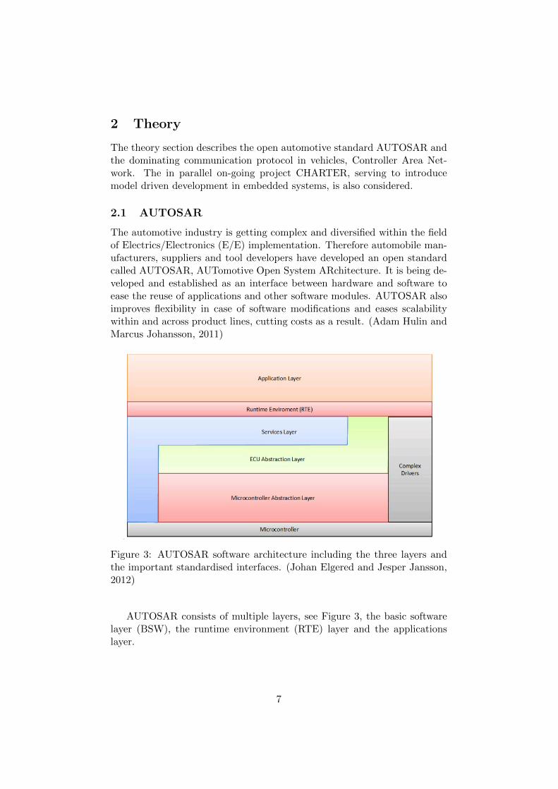
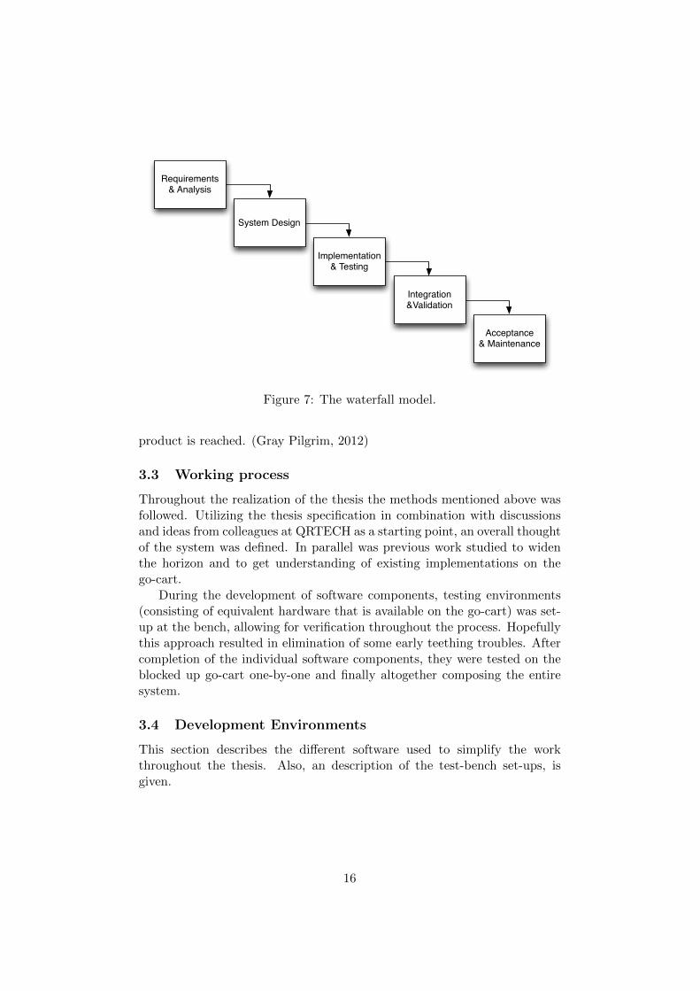
The roots of the waterfall model stretches back to the 1970s, but it is stillused widely due to its simplicity, and wherefore it is also used in the thesis.As can be seen in Figure 7, the waterfall model is divided into differentphases. In the first phase is the requirements (which originates from the enduser’s, in the thesis case QRTECH’s goal) defined as a set of functions andconstraints. A validation of these as well as the possibility of incorporatingthem are also done in the first phase. In the second phase, the requirementsare used to make an overall system design, giving an idea on how the sys-tem is going to work and look like for the end user. In the third phase, theimplementation and unit testing phase, the system is realized as a set ofindependent units/modules (heads-up display, cruise controller, CAN inter-face etc). In the fourth phase, the units/modules developed in the previousphase are put together to make a complete system. Checks and testing areperformed to verify that the units/modules coordinates properly with eachother and that the entire system works as specified. If everything worksproperly, the system is delivered to the end user and might be maintained(if agreed upon at the beginning of the project) when necessary. (NileshParekh, 2011)
3.2 Agile model
After a while it was realized that the stiffness of the waterfall model neededto be complemented with a more volatile method. Agile modelling is a mod-elling technique which developed in the 1990s as a reaction to the existingheavy regulating methods, serving to make projects open to inputs and to’move quickly’. Less focus is put on documentation between different phases,and instead is the development allowed to take sudden turns and changes.A close interaction with the end user through the whole developing processis often significant, which usually lead to a lot of prototypes before the final
15
Requirements & Analysis
System Design
Implementation & Testing
Integration &Validation
Acceptance & Maintenance
Figure 7: The waterfall model.
product is reached. (Gray Pilgrim, 2012)
3.3 Working process
Throughout the realization of the thesis the methods mentioned above wasfollowed. Utilizing the thesis specification in combination with discussionsand ideas from colleagues at QRTECH as a starting point, an overall thoughtof the system was defined. In parallel was previous work studied to widenthe horizon and to get understanding of existing implementations on thego-cart.
During the development of software components, testing environments(consisting of equivalent hardware that is available on the go-cart) was set-up at the bench, allowing for verification throughout the process. Hopefullythis approach resulted in elimination of some early teething troubles. Aftercompletion of the individual software components, they were tested on theblocked up go-cart one-by-one and finally altogether composing the entiresystem.
3.4 Development Environments
This section describes the different software used to simplify the workthroughout the thesis. Also, an description of the test-bench set-ups, isgiven.
16
3.4.1 Eclipse Java IDE
Eclipse IDE for Java Developers is an Integrated Development Environment(IDE) featuring code-completion, syntax highlighting and search functional-ities as well as giving the possibility to test-run the class files in the OracleJava Runtime Environment (JRE) with a simple click, making developmentand testing effective and easy. (The Eclipse Foundation, 2012)
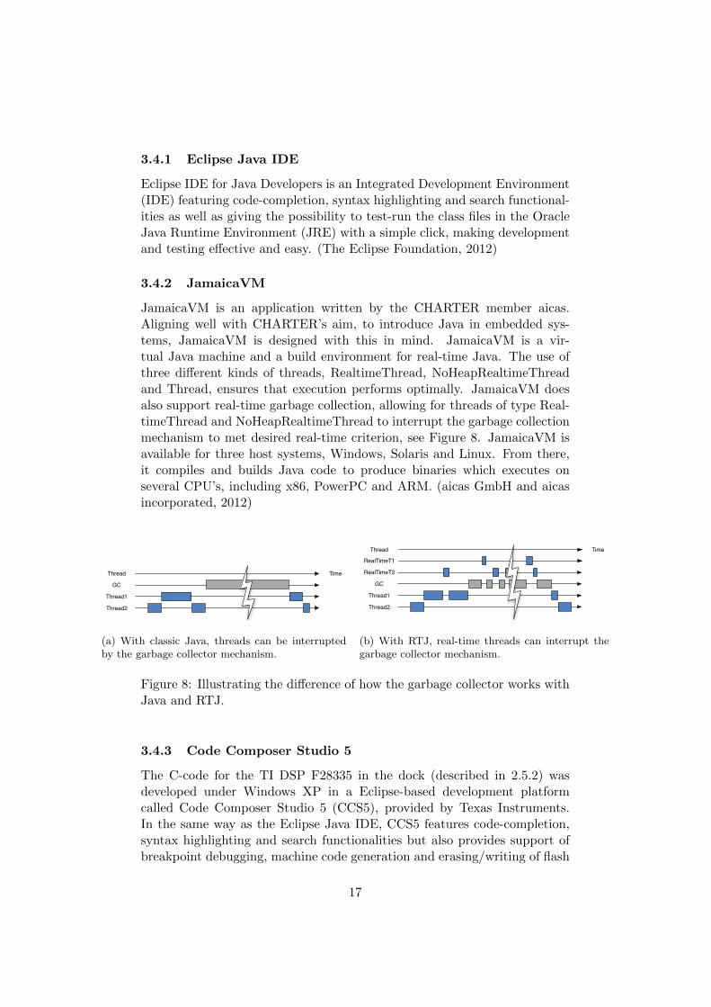
3.4.2 JamaicaVM
JamaicaVM is an application written by the CHARTER member aicas.Aligning well with CHARTER’s aim, to introduce Java in embedded sys-tems, JamaicaVM is designed with this in mind. JamaicaVM is a vir-tual Java machine and a build environment for real-time Java. The use ofthree different kinds of threads, RealtimeThread, NoHeapRealtimeThreadand Thread, ensures that execution performs optimally. JamaicaVM doesalso support real-time garbage collection, allowing for threads of type Real-timeThread and NoHeapRealtimeThread to interrupt the garbage collectionmechanism to met desired real-time criterion, see Figure 8. JamaicaVM isavailable for three host systems, Windows, Solaris and Linux. From there,it compiles and builds Java code to produce binaries which executes onseveral CPU’s, including x86, PowerPC and ARM. (aicas GmbH and aicasincorporated, 2012)
Thread Time
GC
Thread1
Thread2
(a) With classic Java, threads can be interruptedby the garbage collector mechanism.
RealTimeT1
Time
GC
Thread1
Thread2
RealTimeT2
Thread
(b) With RTJ, real-time threads can interrupt thegarbage collector mechanism.
Figure 8: Illustrating the difference of how the garbage collector works withJava and RTJ.
3.4.3 Code Composer Studio 5
The C-code for the TI DSP F28335 in the dock (described in 2.5.2) wasdeveloped under Windows XP in a Eclipse-based development platformcalled Code Composer Studio 5 (CCS5), provided by Texas Instruments.In the same way as the Eclipse Java IDE, CCS5 features code-completion,syntax highlighting and search functionalities but also provides support ofbreakpoint debugging, machine code generation and erasing/writing of flash
17

through USB. A drawback is that CCS5 took a few minutes to build themachine code and flash the non-volatile memory, making the developmentcumbersome. (TI and Community contributors, 2012a)
3.4.3.1 COM-configurator
QRTECH has an in-house developed program called QRtech COMConfigurator, capable of generating CAN related C-code from an importedXML-file. The imported XML-file is derived from CANdb++ Editor, athird party software developed by Vector. CANdb++ Editor allows fordesign of CAN frames, e.g. selecting not only which signals they shouldconsist of, but also bit-length and parameters like offset and type. It doesalso come with the possibility to set several options, such as how often aframe should be transmitted or if a signals should have an update bit ornot. (Vector Informatik GmbH, 2012)
3.4.3.2 CANoe
CANoe is a PC software used to analyse a CAN network and itsnodes. Nodes, which should be a part of the network, can be simulatedto test the behaviour of all ready existent nodes. By importing a CANdatabase, frames on the CAN bus can be monitored and transmittingframes can be tailor-made through simulated nodes, even under runtime.CANoe also features bus load calculation and the possibility to draw signalgraphs. (Vector Informatik GmbH, 2012)
The software uses a small box called CANcaseXL which is connected tothe host machine through USB. The CANcaseXL is in its turn connected tothe CAN network using a twisted pair cable with D-SUB9 connectors. InFigure 9 CANoe is used to simulate the VMCU sending the frame containingthe vehicle state and requested torque to the DSP, on the go-cart. The greengraph shows the actual torque generated by the motor and the black graphshows the vehicle speed. In the lower-left quarter of the screen-shot, thetransmitting frame can be edited. In the lower-right quarter, all frames andits signals on the bus can be viewed.
3.4.4 Test-bench
Two general test-bench set-ups were used in the thesis. The set-up repre-sented by the dashed box in Figure 10 was used for developing the CANinterface for the motor controller. On a PC running Windows, code wasedited, built and uploaded (via USB) to the DSP with Code Composer Stu-dio 5. The PC was also running CANoe and a CANcaseXL was connectedto the PC via USB. With a twisted pair CAN cable with DSUB-9 connectors
18

Figure 9: Here CANoe is used to simulate the VMCU node when developingthe CAN interface on the motor controller.
the DSP’s CAN controller was interconnected to the CANcaseXL. Further-more, especially in the first half of the thesis, an oscilloscope was used tomonitor the duty cycle of the PWM-signals from the motor controller.
The dashed-dotted box in Figure 10 represents the heads-up displaytest-bench. The GUI was designed on Windows XP in Eclipse Java IDEand test run with the Java Runtime Environment (JRE). When testing ontarget hardware, the VMCU, JamaicaVM on Ubuntu Linux 11.10 was usedto cross-compile and build the binary. The executable was then transferredfrom the PC to the VMCU via the intranet.
With a complete AUTOSAR architecture in place on the VMCU, theCAN controller was tested by connecting it to the CANcaseXL in the samemanner as for motor controller development. However, this time CANoesimulated the CAN controller of the DSP or the actual DSP itself was con-nected.
19

VMCU
ARM7
5"
05
10 1525
20
2200 RPM
WiFi
Internet
CANCase XL
angstrom
PC
WindowsXPUbuntu Linux 11.10
JamaicaVMEclipse JavaCANoeCOM ConfiguratorCode Composer Studio 5
USB
CAN
USB
DSP
TI F28335
CANController
PCA82C251
Oscilloscope
TPBP
TPBP
CANControllerISO1050TI
Figure 10: The test bench set-up.
20

4 Implementation
This section describes the design of the AUTOSAR software components,the heads-up display and the cruise controller. The implementation of theCAN interface on the motor controller is also treated.
4.1 Heads-up Display
The graphical user interface (GUI) for the heads-up display was developedin Java using the Java libraries awt and Swing. (Skansholm, 2005) The useof more extensive graphical frameworks such as Java FX was desired butdiscarded due to low or non-existent Angstrom support.
A non-complete but working RTE-layer, together with a test interfacefor setting variables/signals in the RTE-layer, was early integrated with theheads-up display, allowing for testing and validation throughout the process.(For a reminder of RTE, see Section 2.1.2)
The heads-up display consists mainly of Java Swing components, such asJPanels and JLabels. To place the components in the JFrame, a combinationof the classes FlowLayout and TableLayout were used. TableLayout is acustom non-standard Java class which allows for exact positioning in a grid-like structure, making the placement of components easier compared to usingthe default layouts in Swing (http://java.sun.com/products/jfc/tsc/articles/tablelayout/).
At first, vehicle data such as speed, temperature, revolutions per minuteand state of charge, was presented to the driver using JPanels and JLabels.The speed is also displayed in a more convenient way, using the drawlinecomponent in Swing’s 2D Graphics library, which was used to draw a needlein a velocimeter. To create the velocimeter, eight JLabels (each containingdigits representing a speed) were placed in a third of a circular arc, with anequal distance between each other, see Figure 11a.
The drawline method paints a line between two defined coordinates.Thus, by calculating new coordinates for one of endpoint of the line, it ispossible to make the needle rotate and follow the circular arc according tothe changes in speed.
To make the heads-up display more attractive, an external font was used.The font can be described as having a retro-digital-watch-look, based on aseven segment display. It had also to be monospaced to avoid movementsof text, since the letters did not have the same width. The font used isDS-Digital and is a shareware font created by Dusit Supasawat (http://www.dafont.com/ds-digital.font).
The battery indicators used in the driving view (Figure 11a) and thebattery view (Figure 11b), are based on another 2D Graphics GUI Swingcomponent, namely the drawrect. An instance of this component createsthe rectangle representing the border of the battery. To indicate the state
21

of charge, the standing rectangle is filled with the corresponding number ofunderlines stapled one another, see Figure 11a.
Since the needle, especially when moving, looked jagged, the Java ren-dering hints parameters were changed (for example enabling anti-aliasing)to improve the appearance of the graphical representation. The batteryindicators also used this setting.
The heads-up display, as explained in 1.1.2, consists of five views: driv-ing, battery, diagnostics, properties and demo. The option to switch betweendifferent views is available through the menu to the right. It contains fiveJLabels, each with an attached ActionListener, setting the visibility of thepressed view to true and all others to false when clicked. It also prohibitsunnecessary operations to be made on views that are not visible, increasingperformance.
A picture containing the views can be seen in Figure 11.
(a) The driving view (b) The battery view
(c) The properties view (d) The demo view
Figure 11: The different views of the heads-up display.
The driving view is the main view providing information to the driverabout the vehicle’s current state. It shows the speed, both with the ve-locimeter and a numerical value, the average speed, the total distance driven,revolutions per minute, the motor temperature and power status, such ascurrent drain and state of charge. See Figure 11a.
The battery view presents the state of the individual cells in the batteryand general battery status, such as state of charge and temperature, seeFigure 11b.
The diagnostics view shows a button, providing the possibility to clearDTC:s after the driver has been informed about the occurrence of the error.
22

In the properties view, the driver can select which driving profile to use,enable or disable battery charging and decide if the menu should be placedto the left or to the right. See Figure 11c.
In the demo view, the driver is shown a brief presentation aboutQRTECH. A power point presentation was segmented into pictures whichare displayed with the media player delivered with Angstrom, mplayer, show-ing each slide for 5 seconds. See Figure 11d.
Figure 12: Mapping of throttle pedal position to the reqeusted torque, forthe three different driving profiles.
Another feature requested by QRTECH, is the option to choose betweendifferent kinds of driving profiles. Therefore, three profiles are built intothe go-cart, Normal mode, where the throttle position is mapped 1:1 to thetorque request, ECO mode, where the requested torque is mapped 1:2 tothe throttle position, and Sport mode, where the request torque is mapped2:1 to the throttle position and set to maximum torque when the pedal ispressed halfway or more, see Figure 12. The profile selection is made in theproperties view.
4.2 Cross-compilation for ARM with JamaicaVM
When a fairly complete version of the heads-up display was ready it was com-piled and built using JamaicaVM. This was done under Ubuntu 11.10 withthe JamaicaVM cross-compiler for ARM7, referring to the class containingthe main method, using the command:
jamaicac -useTarget linux-arm-le -verbose -d ../classes
RTE/Rte.java
23

which compiles the Java code, essentially building class files in the samemanner as the standard Java compilation command (javac). Typing:
jamaicabuilder -target=linux-arm-le -XstaticLibraries "stdc++"
-verbose=1
-resource+=ds-digi.ttf:ds-digii.ttf:ds-digib.ttf:ds-digit.ttf
-object=BSW/SocketCAN/BSW_SocketCAN_SocketCAN.o RTE/Rte
then uses the class files to generate C-code which is built to a binaryexecutable on the ARM platform. Note how the custom fonts are addedto the binary as resources and how the JNI coded in C++ is passed tojamaicabuilder using the -object flag. Since jamaicabuilder needs a fewminutes to build the 18MB binary, the heads-up display was developed andtested as far as possible in the Java virtual machine (JVM) before buildingwith jamaicabuilder. However, when a binary was built, it was transferredto the VMCU using its wireless internet connection. On the target systemit was run (after setting execution flags) with:
chmod +x Rte
./Rte
4.2.1 Profiling
It was discovered that execution of the binary generated by JamaicaVM wasa lot heavier than running the class-files in the JRE. The solution was foundin the profiling feature of JamaicaVM. By calling the profiling flag whenrunning jamaicabuilder, a special version of the binary is generated:
jamaicabuilder -target=linux-arm-le -XstaticLibraries "stdc++"
-profile -verbose=1
-resource+=ds-digi.ttf:ds-digii.ttf:ds-digib.ttf:ds-digit.ttf
-object=BSW/SocketCAN/BSW_SocketCAN_SocketCAN.o RTE/Rte
When running this version on the target system (ARM), the programchecks which parts of the program that is slow and/or uses a lot of CPUcycles and from this information generates a so called profile. The binaryis then rebuilt passing the generated profile to jamaicabuilder using the -useProfile flag. Setting options such as number of threads, heap size andhow much of the code that is compiled also increases execution speed.
jamaicabuilder -target=linux-arm-le -XstaticLibraries
"stdc++" -useProfile ../RTE.Rte.prof -numThreads 20
-percentageCompiled 50 -heapSize=192M -verbose=1
-resource+=ds-digi.ttf:ds-digii.ttf:ds-digib.ttf:ds-digit.ttf
-object=BSW/SocketCAN/BSW_SocketCAN_SocketCAN.o RTE/Rte
24

The new binary is now tailor-made for maximal performance with satis-fying results.
4.3 Motor controller and CAN interface
There are two primary parts of the DSP program: the PWM-interrupt andthe software interrupt.
The PWM-interrupt serves to control the electric motor, it is triggeredat a 20 kilohertz rate and is essentially the work of the previous master’sthesis on the go-cart at QRTECH (see section 1.1.3.1). Its purpose is to readsensors providing information such as winding currents and temperature aswell as reading the throttle and brake pedals and from this data react andcontrol the current supplied to the motor and its fan by altering the dutycycle of PWM-signals.
In the thesis a new version of this routine was created. In the new versionupdate bits in the CAN frames are set when signals such as motor speedand temperature are recalculated. Furthermore, the throttle and brake ped-als are not read by the analog/digital converter measuring potentiometers.Instead, the variable taking care of the requested torque is set by readingan incoming signal in a CAN frame.
Normally, when the PWM-interrupt is not executing, the DSP is busywaiting in the main function. However, every tenth millisecond a softwaretriggered CPU-timer permits the DSP to execute code which purpose is toserve the CAN controller. The CPU-timer allows for well-timed periodicreception and transmission of CAN frames. Also, no code serving CANcommunication is executed during the PWM-interrupt and thus not delayingthe PWM-signal generation to the motor. This is important since motorcontrol performance is dependent on an agile PWM-routine.
When the software interrupt is triggered, the DSP reads the update bitsof all signals received. If the update bit is set, the value of the correspondingCAN signal is copied to an on-memory allocated variable. However, if amaximal number of update bits have been read in its low state, an error istriggered.
When the variables have been updated, the routine checks the state ofthe vehicle operating state variable and takes appropriate action. There arefour states:
• Shutting down. CAN transmission is stopped, however, the DSP isstill monitoring the CAN bus.
• Initiating. CAN communication is triggered and the DSP starts trans-mitting frames.
• Charging. The batteries are charged by the BMU.
25

• Running. The DSP packs the transmitting frame with vehicle data, i.e.vehicle speed, motor RPM, motor torque (current) and temperatureand tells the CAN controller that data is packed and ready to betransmitted.
By reading an input pin called CAN-ON, the DSP decides which ver-sion of the code to run. If CAN is off, the old interrupt routine (readingthe throttle and brake pedals via A/D-converter) is used and the softwareinterrupt does nothing. Instead, if CAN is on, the new altered version ofthe PWM-interrupt is used and the software interrupt takes care of CANreception/transmission as described above.
4.3.1 CAN bus performance
During normal execution of the DSP and the VMCU, it was observed withhelp from CANoe, that the CAN bus load was around 35%. At the sametime, a stress test was performed by decreasing the periodicity of certainframes, resulting in a bus load of 80% (which is common in automotiveindustry), without any peculiar behaviour.
4.4 Cruise controller
To control the PWM-signal to the motor, a PID is used. The cruise controllerwas implemented by adding a second PID to control the input to the motorPID.
Fcc Fmc G+++-vref ve u1 u2
Figure 13: Block diagram of the go-cart including the cruise controller.
The original controller for the motor is illustrated as the block Fmc inFigure 13. Its input signal is a torque request, which is read from the CANbus. When the cruise controller is active, the reference value is not thetorque but instead a by the driver defined speed, vref . Therefore, an extraPID block is added before the original system to adjust for the error betweenvref and v. If the go-cart moves too slowly, the Fcc regulator has to increasethe requested torque (u1) to accelerate the go-cart, and vice versa.
If the actual speed equals the desired speed, the motor controller reusesthe latest torque request as its input, since this torque request resulted inthe desired speed.
26

The integration of a cruise controller was first made on the DSP, eventhough it is supposed to be present on the VMCU at the end of the thesis.This, as the reconstruction of the go-cart was delayed (thus making it avail-able for testing longer than expected), and the fact that the CAN interfacestill was unavailable on the VMCU. Therefore was the PID implementeddirectly on the DSP, as it ought to behave in the same way as if it wouldhave been implemented on the VMCU. The regulator parameters for thePID-controller was selected using manual tuning. KI and KD was zeroedand KP increased until the output started to oscillate. Then KP was halvedand KI increased until the error offset was corrected in a few seconds. Dwas not needed and ignored. After a final optimisation by trial and error,the parameter selection was finally KP = 0.6, KI = 0.005 and KD = 0.0 forthe Fcc.
Having the go-cart and a VMCU with working CAN interface acces-sible again, the DSP cruise controller implementation was ported from Cto real-time Java and implemented as an AUTOSAR software component,running on the VMCU. At the same time, new features were added. Forexample, the speed of the go-cart must exceed 4 km/h to be able to activatethe cruise controller at all. Also, with the cruise controller activated, it ispossible to overtake another go-cart using the throttle pedal to exceed thecruise controller reference speed. When the overtake is done and the throttlepedal released, the cruise controller continues to control the speed, using theearlier reference speed. Of course, pressing the brake pedal deactivates thecontroller.
27

5 Discussion and Conclusion
This chapter presents the final conclusions and discusses problems encoun-tered during the thesis. It explains the outcome and argues the choicesmade and how issues have been treated and solved. Finally it proposessome subjects suitable for future work.
5.1 Discussion
At the beginning of the thesis, the heads-up display was developed on anunintended platform, resulting in performance issues when later executedon the target platform. Painting and repainting graphics demanded toomuch of the VMCU, preventing real time processes to be executed in time.To handle this, the update time of the graphical user interface had to beincreased (updated less frequently). Also, more sophisticated methods usedto improve the appearance of the heads-up display were discarded. It canbe added that, according to the developers of JamaicaVM, techniques suchas anti-aliasing are slow in JamaicaVM which also supports the decision todiscard it.
After integrating the heads-up display with the RTE-layer and the soft-ware components it came with, performance was yet again an issue. Incontrast to the very deterministic digital signal processor, the behaviour ofthe VMCU was inconsistent. Activating the CAN interface made the GUIslow and unresponsive. Analysing the bus it could be seen that the framessent from the VMCU was forming a queue and was therefore delayed. Also,stressing the VMCU by frequently changing view on the heads-up displaysometimes caused the CAN communication to lag behind too much. Theproblem was avoided by increasing the periodicity of the transmitting framefrom 10 milliseconds to 20 milliseconds, giving the VMCU more time forrepainting the GUI. Increasing the periodicity comes with an additionaldomino effect. Since certain frames are transmitted less frequently, the datathey contain do not need to be updated and calculated as often as before,lowering the load of the VMCU even more.
Error handling, or more specifically, diagnostic trouble codes (DTCs)was part of the thesis description. The codes was to be displayed in a forthe purpose dedicated view, the diagnostics view, indicating errors presenton the CAN bus nodes. The diagnostic view should also have offered thepossibility to clear these errors. Unfortunately, these features had to beset aside, since the work with the performance issues of the VMCU turnedout to be time consuming. Even though the DTCs missed out, some othersafety features have been built in. For example if the CAN bus for somereason is broken between the VMCU and the DSP, the DSP recognises thiscircumstance and sets the requested torque to zero, shutting down the motor.In the same manner, the go-cart motor is shut down if too many frames
28

arrives without the update bit being set.Unfortunately was the go-cart reconstruction not completed before the
end of the thesis, preventing the go-cart being tested on the ground. Eventhough the cruise controller behaved as expected when the go-cart wasblocked up, it is hard to tell how it would behave with the go-cart on theground with load (driver). Hopefully, only minor control parameter adjust-ments of the cruise controller is enough to adapt it to the new environment.
5.2 Conclusion
The thesis resulted in the electric go-cart being equipped with a VMCU, witha heads-up display presenting data to the driver, a drive-by-wire feature viaCAN and a cruise controller making it possible to maintain a desired speed.
The fact that a JNI had to be written in C++ to be able to accessthe VMCU CAN controller at all, is of course a general drawback with(real-time) Java. It makes development more complex, adding another pro-gramming language to the project. AUTOSAR does serve as a specificationfor how interfacing between software layers is treated to extend reusabil-ity, it does not specify which language to use for implementing these layers.However, it can be concluded that a RTJ approach is possible when im-plementing AUTOSAR even though some compromising may be necessarywhen working close to hardware.
It can be concluded that there is space for improvements on the VMCU.Both the heads-up display and the CAN communication on the VMCU canbe optimised for performance and stability. Regarding the DSP, it works ina deterministic manner, meeting its deadlines.
Comparing the actual time spent with the Gantt-chart, (see AppendixA), it can be concluded that the time used for the heads-up display wasextended, stretching almost the whole thesis. In contrary, the work withthe CAN interface and the motor control was finished in a few weeks, whilebeing planned for more than ten weeks. Unfortunately, the DTCs had to beleft out for future work.
29

References
Adam Hulin and Marcus Johansson (2011), Test application generator forautosar systems, Master’s thesis, Department of Computer Science andEngineering at Chalmers University of Technology.
aicas GmbH and aicas incorporated (2012), “Jamaicavm—java technologyfor realtime”, Collected 2012-04-27 . http://www.aicas.com/.
Alec Dorling (2012), “Charter project”, Collected 2012-01-20 . http://
charterproject.ning.com/page/charter-project.
AUTOSAR (2012), “About autosar”, Collected 2012-02-03 . http://www.
autosar.org/.
Computer Solutions Ltd (2012), “Can - a brief tutorial”, Collected2012-03-05 . http://www.computer-solutions.co.uk/info/Embedded_tutorials/can_tutorial.htm.
Corrigan, S. (2002, revised 2008), “Introduction to the controller area net-work (can)”, Application Report , p. 14.
Gray Pilgrim (2012), “Waterfall model vs agile”, Collected 2012-01-17 .http://www.buzzle.com/articles/waterfall-model-vs-agile.html.
Hans Sanell and Goran Samuelsson (2011), In vehicle infotainment demon-strator, Master’s thesis, Department of Computer Science and Engineeringat Chalmers University of Technology.
Joakim Plate and Peter Fridlund (2011), Xcp over can and ethernet on au-tosar, Master’s thesis, Department of Computer Science and Engineeringat Chalmers University of Technology.
Johan Elgered and Jesper Jansson (2012), Autosar communication stackimplementation with flexray, Master’s thesis, Department of ComputerScience and Engineering at Chalmers University of Technology.
koen (2011), “The Angstrom distribution introduction”, Collected 2012-04-04 . http://www.angstrom-distribution.org/.
Lennartsson, B. (2000), Reglerteknikens grunder, 4:7 edn, Studentlitteratur.
Nilesh Parekh (2011), “The waterfall model explained”, Collected 2012-03-19. http://www.buzzle.com/editorials/1-5-2005-63768.asp.
Robert Bosch GmbH (2012), “What is can?”, Collected 2012-03-07 . http://www.semiconductors.bosch.de/en/ipmodules/can/
whatiscan/whatiscan.asp.
30
Skansholm, J. (2005), Java direkt med Swing, 5:4 edn, Studentlitteratur.
The Eclipse Foundation (2012), “Eclipse ide for java developers”, Col-lected 2012-05-02 . http://www.eclipse.org/downloads/packages/
eclipse-ide-java-developers/indigosr2.
TI and Community contributors (2012a), “Code composer studio (ccstu-dio) integrated development environment (ide) v5”, Collected 2012-05-04. http://www.ti.com/tool/ccstudio.
TI and Community contributors (2012b), “Tms320f28335”, Collected 2012-02-10 . http://www.ti.com/product/tms320f28335.
Vector Informatik GmbH (2012), “The development and test tool for can,lin, most, flexray, ethernet, wlan and j1708”, Collected 2012-02-28 . http://www.vector.com/vi_canoe_en.html.
31

A Gantt chart
IDTa
sk N
am
eSt
art
Fin
ish
Du
rati
on
jan
20
12
feb
20
12
ma
r 2
01
2a
pr
20
12
ma
j 20
12
22
-12
9-1
5-2
12
-21
9-2
26
-24
-31
1-3
18
-32
5-3
1-4
8-4
15
-42
2-4
29
-46
-51
3-5
20
-52
7-5
3-6
12
w2
01
2-0
2-0
32
01
2-0
1-2
3P
lan
nin
g re
po
rt
26
w2
01
2-0
3-0
92
01
2-0
1-3
0H
ead
s-u
p d
isp
lay
6w
20
12
-05
-11
20
12
-04
-02
Cru
ise
con
tro
l
2w
20
12
-05
-18
20
12
-05
-07
Erro
r h
and
ling
7w
20
12
-03
-23
20
12
-02
-06
CA
N in
terf
ace
3 871
w2
01
2-0
6-0
12
01
2-0
5-2
8O
ral p
rese
nta
tio
n a
nd
op
po
siti
on
18
w2
01
2-0
6-0
82
01
2-0
2-0
6Fi
nal
rep
ort
44
w2
01
2-0
4-2
02
01
2-0
3-2
6M
oto
r co
ntr
ol
5 6