imaging of ferromagnetic domains by neutron interferometry
TRANSCRIPT

IMAGING OF FERROMAGNETIC DOMAINS BY NEUTRON INTERFEROMETRY
M. S C HLENKER a, W. BAUSPIESS b' c, W. G R A E F F b' d, U. BONSE b and H. RAUCH e Institut Laue-Langevin, 156X, 38042 Grenoble Cedex, France
Ferromagnetic domains in Fe-3% Si were observed by neutron phase-contrast imaging, using a perfect crystal Bragg-diffraction interferometer and unpolarized neutrons. Domain contrast is observed when full interference, with a magnetic reference field, is used, while wall contrast is encountered without field.
Phase-contrast imaging using a perfect-crystal Bragg-diffraction interferometer (for a review, see ref. [1]) was pioneered in the X-ray case by Ando and Hosoya [2]; in the neutron case, the mean magnetic field B directl.y affects the velocity, hence the phase of the neutron wave function, making it in principle possible to observe ferromagnetic domains via the local changes in intensity caused by the inhomogeneous distribution of B they en- tail.
The principle of the experiment, set up on the diffractometer for perfect crystals and interferome- try, DI8, at Institut Laue-Langevin [3], is shown in fig. 1: a perfect-crystal silicon monochromator, using a 220 reflection in an asymmetric Bragg (reflection) geometry, illuminates the interferome- ter, made up of a monolithic, almost perfect single-crystal silicon crystal with 0.6 mm thick plates cut out parallel to (001), operating on the 220 reflection in symmetrical Laue geometry on each blade. An aluminum compensator plate [4], with a relief carved out to match the phase inho- mogeneities due to the interferometer's deviation from perfection, is positioned in beam II, while the specimen, a 0.1 mm thick plate of cube-textured Fe-3% Si containing a large, very well oriented grain, mechanically and electrolytically polished, is placed across beam I. A schematic diagram of the domains is shown in fig. 4.
In the normal interferometric mode of opera- tion, using unpolarized neutrons, contrast can be expected between domains only if the reference beam (here beam II) is submitted to a magnetic
aAlso: Laboratoire Louis N~el, Laboratoire propre du CNRS, associ6 it rUniversit6 Scientifique et Mrdicale de Grenoble, B.P. 166, 38042 Grenoble, France.
bLehrstuhl fiir Experimentelle Pbysik I. Universifiit Dortmund, Fed. Rep. Germany.
cPresent address: Kienzl¢, Villingen, Fed. Rep. Germany. aPresent address: DESY, Hamburg, Fed. Rep. Germany. "Atominstitut der Osterreicbischen Universit~ten, Wien, Austria.
10ml
a
Fig. 1. Beam distribution in the interferometer; D: photo- graphic detector.
field: qualitatively, it is clear that unpolarized neu- trons cannot distinguish up and down magnetiza- tion if no reference direction is built-in. A magnetic field is provided by a soft-iron magnetic circuit with adjustable yoke-pieces, normal to the horizon- tal scattering plane at least in its symmetry plane, and the stray field at the specimen location is kept down to a few oersted.
The image is recorded on X-ray dental film (Kodak Periapical Haute Drfinition) backed by a foil of isotopically enriched 157Gd, a few microme- ters thick, operating as a ( n - r ) converter [5]. Typi- cal exposure times were 48 h. A large specimen to detector distance of about 55 mm was necessary, at the cost of impaired resolution, in order to avoid an overlap of several outgoing beams (see fig. 1).
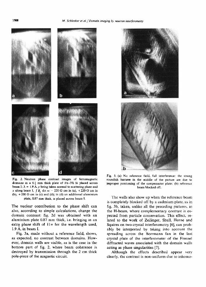
Fig. 2a shows the magnetic domain configura- tion observed when a reference field is applied along beam II; a reversal of the contrast is ex- pected when this reference field is reversed, as in fig. 2b. Changing the integrated reference-field contribution should change the contrast (fig. 2c).
Journal of Magnetism and Magnetic Materials 15-18 (1980) 1507-1509 @North Holland 1507
1508 M. Schlenker et a l . / Domain imaging by neutron interferometry
Fig. 2. Neutron phase contrast images of ferromagnetic domains in a 0.1 nun thick plate of Fe-3% Si placed across beam I; X - 1.9 A. y being taken normal to scattering plane and x along beam I, f By dx ~ - 220 G cm in (a), + 220 Gcm in (b), +330 G cm in (c) and (d); in (d) an additional aluminium
plate, 0.87 mm thick, is placed across beam I.
The nuc lea r con t r ibu t ion to the phase shift can also, accord ing to s imple ca lcula t ions , change the d o m a i n contras t : fig. 2d was ob t a ined with an a lumin ium plate 0.87 m m thick, i.e. br inging in an extra phase shift of l l w for the wavelength used, 1.9 ,~, in beam I.
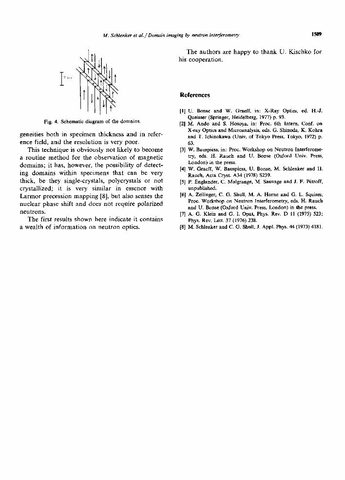
Fig. 3a, m a d e wi thout a reference field, shows, as expected, no con t ras t be tween domains . How- ever, d o m a i n walls a re visible, as is the case in the b o t t o m par t of fig. 2, where b e a m coherence is des t royed by t ransmiss ion th rough the 2 cm thick pole-p iece of the magne t i c circuit .
Fig. 3. (a) No reference field, full interference; the strong roundish features in the middle of the picture are due to improper positioning of the compensator plate; (b) reference
beam blocked off.
The walls also show up when the reference beam is comple te ly b locked off by a c a d m i u m plate, as in fig. 3b, taken, unl ike all the p reced ing pictures, in the H-beam, where c o m p l e m e n t a r y cont ras t is ex- pec ted f rom par t ic le conservat ion . This effect, re- la ted to the work of Zeil inger, Shull, Horne and Squires on two-crys ta l in te r fe romet ry [6], can prob- ab ly be in te rpre ted by tak ing into account the spread ing across the B o r r m a n n fan in the last crysta l p la te of the in te r fe romete r of the Fresnel d i f f rac ted waves assoc ia ted with the d o m a i n walls ac t ing as phase s ingular i t ies [7].
A l t h o u g h the effects desc r ibed appea r very clearly, the cont ras t is non -un i fo rm due to inhomo-
M. Schlenker et al . / Domain imaging by neutron interferometry 1509
i I Fig. 4. Schematic diagram of the domains.
geneities both in specimen thickness and in refer- ence field, and the resolution is very poor.
This technique is obviously not likely to become a routine method for the observation of magnetic domains; it has, however, the possibility of detect- ing domains within specimens that can be very thick, be they single-crystals, polycrystals or not crystallized; it is very similar in essence with Larmor precession mapping [8], but also senses the nuclear phase shift and does not require polarized neutrons.
The first results shown here indicate it contains a wealth of information on neutron optics.
The authors are happy to thank U. Kischko for his cooperation.
References
[I] U. Bonse and W. Graeff, in: X-Ray Optics, ed. H.-J. Queisser (Springer, Heidelberg, 1977) p. 93.
[2] M. Ando and S. Hosoya, in: Proc. 6th Intern. Conf. on X-ray Optics and Microanalysis, eds. G. Shinoda, K. Kohra and T. lchinokawa (Univ. of Tokyo Press, Tokyo, 1972) p. 63.
[3] W. Bauspiess, in: Proc. Workshop on Neutron Interferome- try, eds. H. Rauch and U. Bonse (Oxford Univ. Press, London) in the press.
[4] W. Graeff, W. Bauspiess, U. Bonse, M. Schlenker and H. Rauch, Acta Cryst. A34 (1978) $239.
[5] P. Englander, C. Malgrange, M. Sauvage and J. F. P~troff, unpublished.
[6] A. Zeilinger, C. G. Shull, M. A. Home and G. L. Squires, Proc. Workshop on Neutron Interferometry, eds. H. Rauch and U. Bonse (Oxford Univ. Press, London) in the press.
[7] A. G. Klein and G. I. Opat, Phys. Rev. D 11 (1975) 523; Phys. Rev. Lett. 37 (1976) 238.
[8] M. Schlenker and C. G. Shull, J. Appl. Phys. 44 (1973) 4181.