image guided brachytherapy carcinoma cervix
TRANSCRIPT

Brachytherapy In Carcinoma Cervix: Part II
Made by: Dr. isha jaiswal
Guided by: Dr. Sandip Barik
Date: 28th July 2015

Contents
• Advances in gynecological brachytherapy• ABS recommendations for HDR BT• Image guided brachytherapy• Steps in IGBT• Imaging• Limitations of (2 D)radiographic imaging• Volumetric imaging• GEC-ESTRO recommendations for cervical cancer BT

ADVANCES IN GYNAECOLOGICAL BRACHYTHERAPY
• Remote after loading HDR BT• Applicator development: Intracavitary (IC), Interstitial (IS) & IC+IS• In corporation of Newer Imaging Modalities: CT, MR, PET, etc.• Advances in Treatment Planning Systems• IGBT: Volume Based Brachytherapy

• The American Brachytherapy Society (ABS) Gynaecologic Cervical Cancer Task group has developed general criteria for the management of cervical cancer, designed to guide Radiation Oncologists and assist in making decisions regarding therapy

Gynaecologic Brachytherapy*
General Inclusion Criteria: Stage IA1-IA2 1B1:IB2 - IVA :radically with concurrent chemo radiation followed by BT Stage IVB cervical cancer :may be palliative treated with BT with or without EBRT
Exclusion Criteria:Absolute contraindications to radical treatment Prior pelvic radiotherapy with brachytherapy Life expectancy < 6 month
The use of (IMRT) or 3D CRT is not a substitute for brachytherapy.
*American Brachytherapy society cervical cancer task group

All treatment, including EBRT & BT must be completed within 56 days from initiation.
HDR-BT commences after 45Gy with up to 2 #/week during the conclusion of EBRT and during the parametrial boost portion of treatment. BT may be initiated earlier(but no earlier than approximately 20 Gy), if the physician determines that the applicator placed at this time point is adequate.
Chemotherapy is not typically given on the days of HDR-BT
Timing of BT
American Brachytherapy society cervical cancer task group

Pre-implant evaluationApplicator selection & insertionImagingDelineationPrescriptionTreatment planningTarget dose specificationTreatment delivery
Steps In IGBT
American Brachytherapy society cervical cancer task group

patient should have a detailed gynecologic examination assess the anatomy, residual tumor & decide brachytherapy applicator best suited appropriate medical evaluations and a pre procedure anesthesia assessmentinstructions on fasting, bowel preparation, and preoperative testing, including laboratory studies, should be provided
Pre-implant evaluation

Variety of applicators
tandem and ovoids tandem and ring tandem and cylinder, tandem and ovoid or ring with guides for interstitial needles

APPLICATOR SELECTION1-Intracavitary applicators Patients with an intact uterus should have a tandem placed;
2-Interstitial application
recommended for extensive cervical lesions extension to the lateral parametria or pelvic sidewall lower vaginal extension, a narrow vaginal apex os not negotiable poorly fitting intracavitary applicators
3-Both if patient had a prior supracervical hysterectomy, a short tandem with interstitial implant
can be used for patients with large, bulky tumors, to enhance coverage of cervix and reduce the dose
to the organs at risk (OAR)

1-Tandem & ovoid • most widely used applicator• largest ovoid that can be placed snugly into the lateral fornices should be
used however oversized ovoids can result in displacement of the applicator down the vagina.
• Fletcher-Suit ovoids provide a wider surface area on the cervix as compared to other applicators
2-Tandem and ring applicator :• Indication: for patients who have shallow vaginal fornices.• Disadvantage: slightly narrower distribution than ovoid result in a higher vaginal dose.

3-Tandem and cylinder:
• Indications: cases with upper vaginal stenosis (inability to place ovoids or a ring)cases with superficial disease involving the lower vagina
• Disadvantage: dose distribution significantly different higher doses to the bladder and rectum, lower dose to the parametrium
4-Tandem and ring or ovoids with short interstitial needles
• for patients with large, bulky tumors, to cover the depth of the cervix and reduce the dose to the organs at risk (OAR)
• The main part of delivered dose results from loading in intrauterine applicators, whereas needles are used to shape, fine tune, and enlarge the treated volume.
• improve lateral coverage by an additional 10 mm when compared with Intracavitary applicators alone

Tandem and ovoid, tandem and ring or tandem and cylinders for intracavitary applications, inserted free hand
Hollow interstitial needles inserted either freehand or with template or ultrasound guidance .
APPLICATOR INSERTION

Imaging after applicator insertion X ray USG CT MRI
When available, the ABS recommends the use of cross-sectionalimaging, such as magnetic resonance imaging(MRI) or computed tomography (CT), to obtain measurementsof tumor size, volume, and extent of disease

LIMITATIONS OF (2 D)RADIOGRAPHIC IMAGING
For determination of target
• point based dosimetry• point A may overestimate or underestimate the tumor dose based on 3D
imaging*
• no optimization:• tumor coverage relies on tumor volume at time of BT, larger tumors requiring
greater optimization to be adequately covered by the prescribed isodose line• Kim et al** found that dose to point A was significantly lower than
the D90 for HR-CTV calculated using 3D image-based optimization
• dose escalation not possible
• *Kim RY, Pareek P. Radiography-based treatment planning compared with computed tomography (CT)-based treatment planning for intracavitary brachytherapy in cancer of the cervix: analysis of dose-volume histograms. Brachytherapy 2003;2:200–206.
• **Kim H, Beriwal S, Houser C, et al. Dosimetric analysis of 3D image-guided HDR brachytherapy planning for the treatment of cervical cancer: is point A-based dose prescription still valid in image-guided brachytherapy? Med Dosim 2011;36:166–170.

AIM
to analyze dosimetric outcome of 3D IGBT &compare dose coverage of HRCTV to traditional Point A dose.
• N=32patients (stage IA2-IIIB cervical cancer) treated with IGBT• dose: 5.0-6.0 Gy/# ×5 fractions. • delineation of CTV as per GYN GEC/ESTRO guidelines. • D90 for HRCTV was 80-85 Gy, • D2cc of bladder, rectum, and sigmoid was limited to 85 Gy, 75 Gy &75 Gy.
• RESULTS• The mean D90 for HRCTV was 83.2 ± 4.3 Gy SD significantly higher (p <0.0001)
than mean value of Point A dose (78.6 ± 4.4 Gy). • The dose levels of the OARs were within acceptable limits • Dose to Point A was found to be significantly lower than the D90 for HRCTV
• Image-based 3D brachytherapy provides adequate dose coverage to HRCTV, with acceptable dose to OARs in most patients.
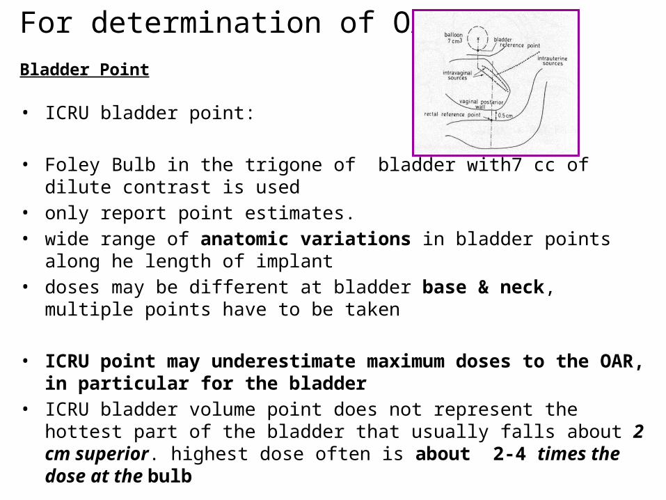
• ICRU bladder point:
• Foley Bulb in the trigone of bladder with7 cc of dilute contrast is used • only report point estimates. • wide range of anatomic variations in bladder points along he length of implant• doses may be different at bladder base & neck, multiple points have to be taken
• ICRU point may underestimate maximum doses to the OAR, in particular for the bladder
• ICRU bladder volume point does not represent the hottest part of the bladder that usually falls about 2 cm superior. highest dose often is about 2-4 times the dose at the bulb
For determination of OAR
Bladder Point

Rectal point
ICRU rectal point:
• rectal markers is used which tend to lie on posterior wall of rectum while the anterior wall is at greater risk.
• Stiff markers can move rectum, flimsy ones are difficult to push deep.• ICRU rectal point doesn’t usually represent the maximum rectal does, which,
again often is 2-4 cm cephalad.• maximum does is up to 3 times the ICRU point
None of this localizes the superior bowel - an organ very much at risk.

Ultrasound
Can be very useful during tandem insertion Localizing the cervical cannel when obscured by large tumor,
detecting a retroverted uterus before tandem insertion. Determines uterine width & height US does not define the target volume as clearly as MRI Transrectal US may assist with interstitial brachytherapy when other
imaging modalities are not available

VOLUMETRIC 3 D IMAGING• Aim to
1. localize the source positions.
2. Localize the target.
3. Localize the organs at risk.
4. Determine the relationships between all the above

CT SCANPlain CT scan is obtained after applicator insertion with 3-5mm cuts
Advantages:• verifies proper placement of applicator• reasonable estimate of the location of uterus • fairly good for visualizing bladder and rectum.• analyses 3D BT dose distribution• depicts changes in the OAR related to tumor shrinkage & filling status.• 3D dose calculations & optimisation possible• OAR dosimetry based on CT is similar to that based on MRI when optimized
similarly*
• long experience in treatment planning for EBRT• readily available in radiotherapy departments
• *Eskander RN, Scanderbeg D, Saenz CC, et al. Comparison of computed tomography and magnetic resonance imaging in cervical cancer brachytherapy target and normal tissue contouring. Int J Gynecol Cancer 2010;20:47–53

Problems with CT treatment planning• produce artifact with metallic applicators• expensive• GTV not identified• overestimate tumor contours compared to MRI (although additional width
contoured on CT may not be of detriment)• fails to provide differentiation between the uterus, cervix, pariuterine tissues
so CT-based contouring guidelines recommend delineating entire cervix and uterus. not provide sufficient detail of tumor if selected dose escalation is required,
• contouring sigmoid difficult due to lack of contrast• contrast placed in OAR may cause artifact.in contouring wall of organ.• requires moving patient after application from CT to treatment room: can
produce motion artifact that nullifies the increased accuracy of IGBT
*Viswanathan AN et al. Computed tomography versus magnetic resonance imaging-based contouring in cervical cancer brachytherapy: results of a prospective trial and preliminary guidelines for standardized contours. Int J Radiat Oncol Biol Phys2007;68:491–498

MRIADVANTAGES• multiplaner imaging
• excellent soft tissue contrast• better visualisation of tumor & parametrium. involvement• differentiate between uterus, cervix, tumor, other pelvic tissues & OAR• particularly useful in patients with advanced or deeply infiltrating tumors.• specific signal intensities allow for distinct separation on T1- and T2 WI
cervix (low T1, low T2), parametrium (high T1, high T2), tumor (low T1, high T2)
• regression of cervical tumors can be documented so dose escalation possible• organ wall may be more clearly visualized for contouring OAR.
DISADVANTAGES• requires special applicators. non-ferromagnetic, metal or plastic/graphite• very expensive• can produce motion artifact
The criteria for an adequate implant (regardless of imaging modality used)
• The tandem should bisect the ovoids on an AP and lateral image.• On a lateral image, the ovoids should not be displaced inferiorly from the flange
(cervical stop) and should be as symmetrical as possible (should overlap one another).
• The tandem should be approximately one-half to one third the distance between the symphysis and the sacral promontory, approximately equidistant between a contrast-filled bladder and rectum-sigmoid.
• The superior tip of the tandem should be located below the sacral promontory within the pelvis
• Radio-opaque packing will be visible on radiographic images and should be placed anterior and posterior to the ovoids, with no packing visible superior to the ovoids.

• Contouring : Targets and OAR’s• Planning : TPS • - Catheter reconstruction• - Loading pattern • - Optimization (Manual / Inverse)
• Plan evaluation • - Doses to HR-CTV, GTV (D90, D100, V100 etc…)• - Doses to OAR’s ( rectum, bladder, sigmoid 0.1 cc, 1 cc, 2cc)
Brachytherapy Planning

DELINEATION Advances in image guidance for applicator insertion and treatment planning have
resulted in 3D tissue contouring guidelines (GEC-ESTRO)
After insertion of applicators, the target volumes and normal-tissue structures are delineated on images in TPS.
The delineation is to be performed at time of each BT application.
The delineation process is based on clinical examination at diagnosis and at BT and on a set of sectional images (preferably MRI T2 weighted) taken at diagnosis and at BT with applicator in place.
Radiotherapy and Oncology 74 (2005) 235–245

Gross tumor volume: GTV
Gross tumour volume (diagnosis) (GTVD) includes macroscopic tumour extension at diagnosis as detected byclinical examination (visualisation and palpation) and as visualised on MRI:
Gross tumour volume (BT) (GTVB1, GTVB2, GTVB3,.) includes macroscopic tumour extension at time of BT as detected by clinical examination and as visualised on MRI:
In patients treated with upfront BT or with BT alone, GTVB is identical with GTVD.

Clinical target volume: CTV
,
HR-CTV :with macroscopic ds. includes GTV + whole cervix + presumed
extracervical tumour extension+ residual ds
Pathologic residual tissue(s) as defined by palpable indurations and/or grey zones in parametria, uterine corpus, vagina or rectum and bladder are included in HR-CTV. No safety margin are added.
IR-CTV :represent significant microscopic ds includes HR-CTV +different safety margins are
added (minimal 5 to 15 mm)
LR-CTV :including potential microscopic spread treated by surgery and/or EBRT

IR-CTV includes HRCTV different safety margins are added according to potential spread5 mm AP limited by bladder or rectum10 mm cranially into uterine corpus10 mm caudally below the cervical os into the vagina.10 mm laterally into both parametria, usually representing internal third of the
parametrium+ 5 mm if endocervical tumour in BT only+ 5 mm laterally if lateral macroscopic tumour in BT only
IRCTV: for limited disease (tumour size<4cm)
Schematic diagram for limited disease, with GTV, high risk CTV and intermediate risk CTV :coronal and transversal view

IR-CTV: for extensive disease
• IR CTV is based on macroscopic tumour at diagnosis (GTVD) which is superimposed on HR-CTV at time of BT (ie GTVBT + Cervix + extracervical tissue)taking original anatomical tumour spread as reference
• Margins are added depending on the regression in initial tumor extent present at diagnosis
Schematic representation for HR and IR CTV lateral parametrial limits for extensive ds

IR-CTV extensive disease :safety margins
Complete remissionIRCTV=HR CTV(red) + GTVdiagnosis(blue dot)
no safety margin
Partial response: IRCTV include
HRCTV ie GTV + cervix+ extracervical residual ds (e.g. parametria)
+GTVdiagnosis(blue dot)
+safety margin of minimum 10 mm added into the direction of
potential spread (parametria, vagina, uterus)
In case of stable diseaseIRCTV include HRCT
+GTVdiagnosis (blue dot)
+safety margin of 10 mm is added to the initial tumour extension at diagnosis
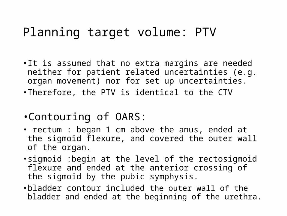
Planning target volume: PTV
• It is assumed that no extra margins are needed neither for patient related uncertainties (e.g. organ movement) nor for set up uncertainties.
• Therefore, the PTV is identical to the CTV
•Contouring of OARS:• rectum : began 1 cm above the anus, ended at the sigmoid flexure,
and covered the outer wall of the organ.
• sigmoid :begin at the level of the rectosigmoid flexure and ended at the anterior crossing of the sigmoid by the pubic symphysis.
• bladder contour included the outer wall of the bladder and ended at the beginning of the urethra.

2007
Purpose: To compare contours and DVH of tumor & OAR with CT vs. MRI in cervical cancer BT
A standardized approach to contouring on CT (CTStd) was developed, implemented and compared with the MRI contours
primary endpoint :assess the feasibility of using these CT-standardized (CTStd) contours to approximate MRI-based treatment parameters.
secondary endpoint: to determine whether CT and MRI provide dosimetrically similar results for the organs at risk (OARs)

10 patients (Stage IIA–IIIB)underwent pelvic EBRT+ CT f/b tandem and ring BT
Planning CT and MRI were performed and contouring carried out separately,no contrast used in study.
MRI contoured in accordance with the GEC-ESTRO recommendations
The CT and MRI volumes were fusedCT contours of the HR-CTVCT and IR-CTVCT were adapted based on the GEC-ESTRO recommendations for MRI.The GTV could not be defined on CT. Also difficulty delineating the superior border of cervix and lateral border of parametria (if involved) and accurate delineation of the OARs
CT Vs MRI CONTOURINGVishwanathan et al. IJROBP 2007

Volumetric and DVH values
A two-sided t test comparing mean values of height, thickness,& volume showed no significant differences among three.
However, the tumor width was significantly different for HR-CTVCTStd and compared with MRI values.
difference in width resulted in statistically significant differences in D100 and D90.

the tumor width was significantly different for IR-CTVCTStd compared with corresponding MRI values resulting in statistically significant differences in D100, and D90
No statistically significant differences in the dose to 0.1 cm3, 1 cm3, and 2 cm3 for the OARs were noted

RESULTSCT significantly overestimated the
width of the tumor and altered the D90, D100
OAR DVH were the sameMRI remains standard for contouring
CT contouring results can be improved by contrast-enhanced imaging integration of information obtained from clinical examinationmultiplaner imaging MRI immediately before brachytherapy

Improving CT Contouring
• Dilute contrast placed directly into bladder can determine lateral recesses.
• Barium inserted into rectal tube placed with tip in rectosigmoid provides adequate sigmoid and rectal contrast.
• sagittal images with the applicator in place can ensure that superior extent of cervix encompasses average cervical height of 3 cm
• identify uterine vessels, which delineate cervicouterine junction .This allows demarcation of upper border of cervix and, therefore, could guide contouring of superior border of HR-CTV.
• However, for patients with tumor extension superior to cervix, only MRI immediately before or at brachytherapy can accurately delineate the superior border of the HR-CTV

TREATMENT PRESCRIPTIONIt should at least include the following items:
• target
• target dose, dose rate
• dose per fraction
• fractionation plan.
Complete description of brachytherapy technique radionuclide; source type (wire, stepping source); source strength; applicator type; type of afterloading (manual or remote); description of additional interstitial needles if any
The treatment plan, including:
• a. The dose distribution to the target and
• b. The critical organs and their dose limits.

Treatment planning
Treatment planning and dosimetry should be performed every time applicators are inserted to assess doses to the target and normal tissues
• Planning : TPS
• Target dose specification
• OAR specification
• Catheter reconstruction:
• Loading pattern
• dose specification & optimisation method, if applied

Radiotherapy and Oncology 78 (2006) 67–77www.thegreenjournal.com

3D dose-volume parameters for BT of cervical carcinoma Defined dose volume parameters for target & OAR Cumulative dose volume histograms (DVH) are recommended for evaluation

Target dose specification for GTV,HRCTV & IRCTV with their uses & limitation
• Minimum target dose(D100) & D90 :minimum dose delivered to 100% &
90% of target
• Uses:
• D100 and D90: both highly recommended for reporting
• can easily be calculated from DVH and converted to EQD2 doses which
makes them suitable for plan comparison of all dose rate techniques.
• D100: limitation: extremely sensitive to inaccuracies in contouring &
dose calculation .Due to the steep dose gradient, small spikes in the contour cause large deviations in D100.
• D90 is less sensitive to these influences and is therefore considered to be a more stable parameter

• V100 :volume receiving 100 % of prescribed dose describes
• Uses:
• V100 asses dose coverage to whole target & is 100 % when entire target
covered by prescribed dose
• Limitation:
• V100 is based on prescribed physical dose, only relevant within a
specific dose rate and fractionation, cannot be used for intercomparison purposes, should be applied solely for intra-patient plan comparison
• The intercomparison problem is avoided when BED are used, e.g. V(60 GyEQD2),V(85 GyEQD2).
• For fractionated treatment, however, this parameter is only usable for evaluation after last fraction, as it uses summed doses of all #.
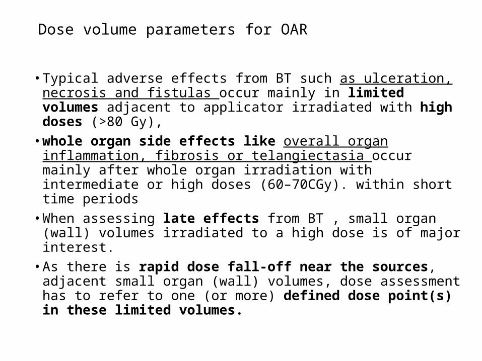
Dose volume parameters for OAR
• Typical adverse effects from BT such as ulceration, necrosis and fistulas occur mainly in limited volumes adjacent to applicator irradiated with high doses (>80 Gy),
• whole organ side effects like overall organ inflammation, fibrosis or telangiectasia occur mainly after whole organ irradiation with intermediate or high doses (60–70CGy). within short time periods
• When assessing late effects from BT , small organ (wall) volumes irradiated to a high dose is of major interest.
• As there is rapid dose fall-off near the sources, adjacent small organ (wall) volumes, dose assessment has to refer to one (or more) defined dose point(s) in these limited volumes.

OAR specification with volumetric imaging
recommendations suggest three quantities to characterize the dose distribution for OAR. .
minimum dose in the most irradiated tissue volume adjacent to the applicator (0.1, 1 & 2 cc) is recommended for recording
D2 cc can be useful during dose planning and for evaluating toxicities
D0.1 cc is indicative of the maximum dose.

RECOMMENDED DOSE PRESCRIPTION
TARGETFor HDR: cumulative dose from EBRT +BT HR-CTV dose: EQD2=85-90Gy The IR-CTV dose: EQD2=60 Gy. Target coverage D90 should be equal to 100 % prescribed dose
OAR D2cc bladder ≤90 Gy EQD2 D2cc rectum & sigmoid ≤70-75Gy EQD2

Radiotherapy and Oncology (2010)
In IGBT :geometry of the applicator is extracted from patient 3D images and introduced into TPS
Due to the steep dose gradients, reconstruction errors can lead to major dose deviations
applicator commissioning and reconstruction methods must be implemented in order to minimise errors.
Applicator commissioning verifies location of source positions in relation to applicator
for optimal visualisation of applicator. Para-transverse imaging with small slice thickness (≤5 mm) is recommended
contouring and reconstruction should be performed in same image series in order to avoid fusion uncertainties.
Under well-controlled circumstances reconstruction uncertainties are in general smaller than other brachytherapy uncertainties.

• MR imaging criteria have to be fulfilled. • Technical requirements, patient preparation, as well as image acquisition
protocols have to be tailored to the needs of BT• pelvic MRI scanning to be performed prior to radiotherapy (‘‘Pre-RT-MRI
examination’’) and at time of BT (‘‘BT MRI examination’’) with one MR imager.• Multiplanar (transversal, sagittal, coronal and oblique image orientation) T2-
weighted images obtained with pelvic surface coils are considered as the golden standard for visualisation of the tumour & OAR.
Radiotherapy and Oncology (2012)

Thank you