ilc conventional facilities - ilc agenda (indico) · pdf fileilc conventional facilities...
TRANSCRIPT

ILC PAC Meeting @LAL Orsay 1
International Linear Collider (ILC)Global CFS Group
ILC Conventional Facilities
Victor R Kuchler
John Andrew Osborne
Masanobu Miyahara
2015/4/13

Contents
• Potential Site in Asian region
• TDR Configuration Overview
• CFS work for Change Requests
• Project Schedule - Next Steps
2015/4/13 ILC PAC Meeting @LAL Orsay 2

Asian Potential Site : KITAKAMI
LAND Features: ILC Site is located in south-west of Kitakami Highland. Land is almost covered forest, agriculture and daily farms. ILC Route is sloping terrain accessible to the underground.
Access to the Site
Tohoku
Tokyo
Kitakami
Panoramic view from the top of AWARA-Yama mountain
Landscape along the ILC Route
Climate: Annual average temperature: 10.8℃ (51.4℉)
Coldest month (Feb) : -4.8℃ (23.3℉ ) Annual precipitation : 1,338 mm Maximum amount of snow: 30 cm
2015/4/13 ILC PAC Meeting @LAL Orsay 3
Potential site conditions

- 2005First Preliminary survey<Iwate Pref.>
- 2009Second Preliminary Survey <Iwate Pref.>
- 2010Third Preliminary Survey
<Iwate Pref. & Tohoku Univ.>-2011
Ground Water Survey <Tohoku Univ.>
Geological Investigation
Sendai ●
KitakamiHighland
Pacific Ocean
- 2015Investigation Plan at the new IP area <Iwate Pref. and Tohoku Univ.>
Currently in Contract process
Potential site conditions
- 2012~13Investigation of candidate site conditions <KEK, Tohoku Univ. & Kyushu Univ.>
Topographic Map
2015/4/13 ILC PAC Meeting @LAL Orsay 4
Environmental Assessment- 2013~14
Pilot Survey (Field Survey of Raptor) <IWATE Pref.>

Bedrock Properties in Central Region
5
Potential site conditions
IP
ILC PAC Meeting @LAL Orsay2015/4/13
P-wave velocity around IP
IP
北
南
N
S
Seismic exploration result:・ Distribution of the stable Bedrock zone in whole central region.・ P-wave velocity: more than 5km/s・ The distribution of the low-velocity layer can be seen partially.
Key Plan
IP

ORIKABE Granite
3D Geographical Map
3D Bird’s-eye view from the North side
HITOKABE Granite
● OSHU
● ICHINOSEKISENMAYA Granite
ORIKABE Granite
Pacific Ocean
IWATE Pref.
MIYAGI Pref.
S
Laser rangefinder
GPS Satellite
GPS Satellite
Aerial Laser survey
※DEM: Digital Elevation Model
2015/4/13 ILC PAC Meeting @LAL Orsay 6
Potential site conditions

Design and Optimization
• Understanding of the Geology, Geography and natural environment is extremely essential requirements for civil engineering design.
• Natural Bedrock itself will be the tunnel structure in NATM tunneling.Grasp of the detailed bedrock properties is the most important item.
• 3D Design Integration with the Geology, Geography & Accelerator Lattice is needed to optimize the underground facilities layout
LatticeAccess Halls
Utility Halls
Surface
Design Integration in the Mountain site
2015/4/13 ILC PAC Meeting @LAL Orsay 7
Potential site conditions
Access Tunnel

Electric Power Infrastructure
Electric Power Demand of the ILC operation is about 1.5 % of the total Supply Capacity of Tohoku region (6 Prefectures)
The current supply reserve capacity maintains over 10%.
Electricity demand of the Tohoku districtslightly has more winter than summer.
11.6
5.2 7.1
11.8 12.0 11.1
0.0
10.0
20.0
30.0
40.0
0
5,000
10,000
15,000
20,000
SM 2011/8 WT 2012/2 SM 2012/8 WT 2013/1 SM 2013/8 WT 2014/2
Power Supply Status
Supply Capacity
Demand
Reserve Capacity
Reserve Rate
MW Reserve Rate
Data By Tohoku EPCO public document
EP Infrastructure of Tohoku District
2015/4/13 ILC PAC Meeting @LAL Orsay 8
Potential site conditions

Detector Hall
Underground Facilities
Accelerator Tunnel Length 39.7 km
Cavern Volumes 520,000 m3
Overall of the ILC Complex
TDR Configuration
CRYOMODULE KLYSTRON
2015/4/13 ILC PAC Meeting @LAL Orsay 9
Main Linac

DR
Detector Hall
RTML turn-around
Access Hall
(The background picture shows a similar site image but not the real site.)
Access Facilities Layout
AS-X Access Station on Surface
Access Tunnel
Access Road
AS-1AS-2
AS-3AS-4
AS+2 AS+3
AS+4
AS-0a AS+1
Access Road (Existing)
Mountain site Image
Access TunnelAccess Tunnel
Central Campus
Access Station
RTML
Central
Substation
Access Hall
Utility BuildingInstall HouseSubstation
Access Portal
AS-0b
Accelerator Tunnel
Wave guide system
He Compressor
Cooling Water
He Cold box2K
Access Tunnel
Substation
TDR Configuration
2015/4/13 ILC PAC Meeting @LAL Orsay 10

Main Linac Tunnel
ML Tunnel Standard Section ML Tunnel 3D-image
RF Service Tunnel Beam Tunnel
Concrete Shield-Wall
55
00
mm
Inflow Water Drainage
Lining Concrete
High Power Cables
Cooling Water
TDR Configuration
2015/4/13 ILC PAC Meeting @LAL Orsay 11

Compressor Hall
Damping RingTunnel
Cold Box HallUtility Hall
Kicker Part
1
2
Damping Ring Layout
1Damping Ring Tunnel
RF Part Tunnel
2
BDS Tunnel
6.5
4.7
Detector Hall
加速器側 サービス側
13.0
6.9
Beam LineRF Service
1 2
RF Part Tunnel
TDR Configuration
2015/4/13 ILC PAC Meeting @LAL Orsay 12
Mail Beam Dump

142m
25m
42m
142m
Main Cavern Alcoves ILD
Upper AT
Lower AT
Lower AT
Alcoves SiD
Beam tunnel
20m 20m
Utility Cavern
18m 20.5m
25m
12.5m
12.5m
142m
13
42m
25m
Section
空洞 断面寸法
Main hall H 42.0mW 25.0mL 142.0m
Alcoves H20.5mW 20.0mL 12.5m
Detector Hall
TDR Configuration
SiD
ILD
ILC PAC Meeting @LAL Orsay2015/4/13

CFS Work after TDR
Change Request proposed
1. Detector Hall with Vertical Shaft access (CR-0003)
2. Extension of the ML-tunnel length (CR-0004)
Change Request anticipated in Future
1. ML Shield-wall thickness impact
2. BDS Tunnel configuration
3. Cryogenics facilities Layout
2015/4/13 ILC PAC Meeting @LAL Orsay 14

Access TunnelW8m Grad10%
Access TunnelW11m Grad7%
AssemblyYard
DHDR
DR Yard
Access TunnelW8m Grad10%
Overview of the Change Request
AssemblyYard
DR Yard
DHDR
Vertical ShaftUtility shaft D10m
1 DH with Vertical Shaft Access ILC-CR-0003
Vertical ShaftMain shaft D18m
• Change Review Panel Members: K. Yamamoto, V. Kuchler
• Current Status: Accepted by CMB
TDR Baseline
Assembly Place: underground/DH Access way to DH underground
- only horizontal Access Tunnel (AT)- Transport. by special long trailer
New Baseline
Assembly Place: Surface building/AH Access way to DH underground
- mainly Vertical Shaft (VS)- Transport. by Gantry Crane
2015/4/13 ILC PAC Meeting @LAL Orsay 15
CFS Work After TDR
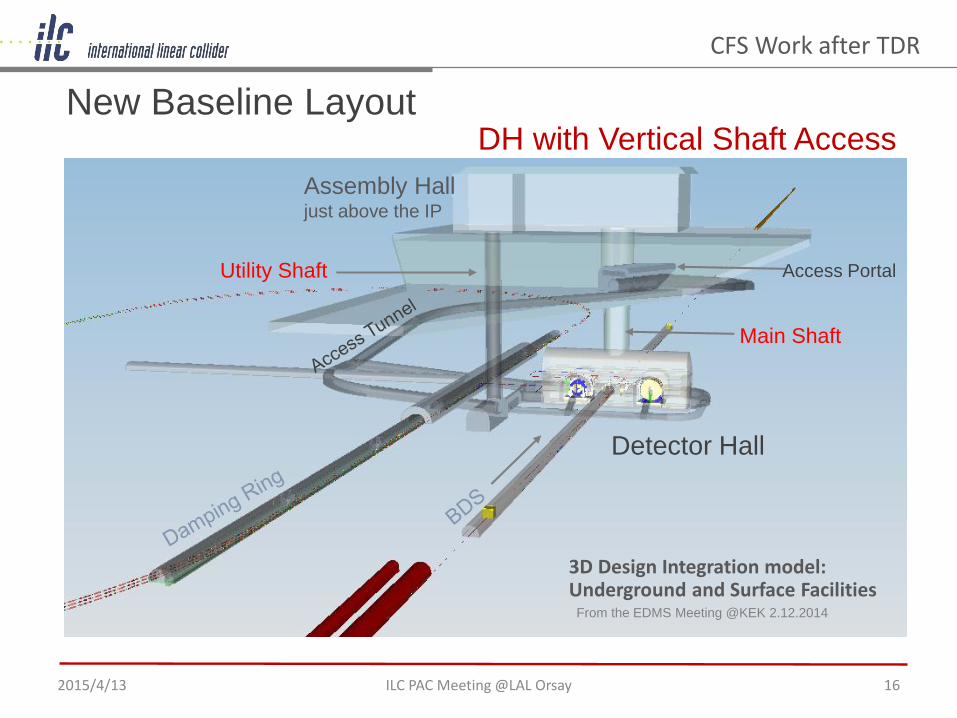
From the EDMS Meeting @KEK 2.12.2014
Assembly Hall just above the IP
Main Shaft
Utility Shaft Access Portal
Detector Hall
3D Design Integration model: Underground and Surface Facilities
ILC PAC Meeting @LAL Orsay 16
DH with Vertical Shaft Access New Baseline Layout
2015/4/13
CFS Work after TDR

TDR Baseline
144m
Utility Shaft
SiD
108m
New Baseline
ILD
ILD SiDMain Shaft MS/D18m
Access Tunnel
Detector Hall Configuration
DR
Access Tunnel
DR
2015/4/13 ILC PAC Meeting @LAL Orsay 17
CFS Work after TDR

• DH construction cost is estimated to be reduced slightly than Baseline.
ItemsBaseline New Baseline Difference
Cost ImpactA B B-A
Civil (Underground Facilities) UPDH Cavern, Access Tunnel 11,500 12,400 900 +7.8%
Architectural (Surface Buildings) EvenAssembly Hall, other buildings 1,590 1,590 0 -
Mechanical Facilities DownLCW & CHW, Air Duct, Plumbing 1,360 165 -1,195 -88%
Handling Equipment Down
Crane, Lowering & Transport, EV 3,570 2,930 -640 -17.9%
Total 18,020 17,085 -935 -5.2%
Total Cost Impact 0~-10%
Cost Impact of the Change Request
DH Construction Cost
2015/4/13 ILC PAC Meeting @LAL Orsay 18
CFS Work after TDR

Change Implementation Plan
• Change Implementation Team Members: V Kuchler (chair), K Buesser, T Markiewicz, B List, M Miyahara, and T Sanuki(Support)
• Current Status: Final draft will be discussed and reviewed at ALWC2015 meeting (Tsukuba/KEK)
Construction Schedule0 12 24 36 48 60 72 84 96 108
TotalAccess TunnelDetector Hall
Assembly HallDetector Assembly
115.934.0
54.523.0
36.0
0 12 24 36 48 60 72 84 96 108
TotalAccess Tunnel
Access ShaftDetector Hall
Assembly HallDetector Assembly
103.022.8
47.354.7
28.0
35.4
116 months
103 months
Baseline
New Baseline
2015/4/13 ILC PAC Meeting @LAL Orsay 19
CFS Work after TDR
• Total construction schedule including the installation term can be reduced for about 1 year compared with the baseline.

Gantry Crane
18m
LHC-CMS
18m
Main shaft D=18m
Center of DH
Detectors Installation
Surface
Gantry Crane
LHC-CMS/CERN
Vertical Shaft Structure
2015/4/13 ILC PAC Meeting @LAL Orsay 20
CFS Work after TDR
70
m4
2m
11
2m
Main Shaft

2 Extension of the ML Tunnel ILC-CR-0004
4907.760 4911.580 3413.787 2334.943 4795.218 4907.760 2509.7172509.717129.258129.258
4907.760 4911.580 3413.787 2334.943 4795.218 4907.760 2509.7172509.717129.258
129.25815001500
TDR Baseline
New Baseline
12,329.063 12,212.695
Additional Tunnel
13,829.063 13,712.695
Under Discussion
• Change Review Panel Members: V Kuchler (chair), N Waker,H Nakai, T Sanuki, M Miyahara
• Current Status: Under Discussion Change Implementation Team
2015/4/13 ILC PAC Meeting @LAL Orsay 21
CFS Work after TDR

Outline of the Change Request Extension of Main Linac Tunnel:• Both the Electron and Positron ML Tunnels by approximately 1.5 km. • Electron Linac Length: 12.3km →13.8 km, • Positron Linac Lebgth: 12.2 km → 13.7 km
Rational: • Adjust the total beam-line path length on the Positron side in order to fulfill the
timing constraint by the baseline method of positron production
Cost Impact of the Change Request 0004
• Current Status: Under Discussion• Further detailed discussion will be planed at ALWC2015
2015/4/13 ILC PAC Meeting @LAL Orsay 22
CFS Work after TDR
Assumption Section Cost
Change Request 0004
Section: 9m x H5.5mShield wall: 1.5m Tunnel Length: 3km
Unit cost: 1,900 kJPY/m
Total cost: 5,700 MJPY

- Beam line : Width 3.8m
- Klystron gallery: Width 3.7m
- Tunnel Inner height :5.5m
Common Dimensions
Beam LineKlystron Gallery
1 ML Shield wall thickness impact Pre-study
• Radiation shield issue will be decided by necessity of person's access• Scheme change depends on the management scenario of beam operation.
2015/4/13 ILC PAC Meeting @LAL Orsay 23
Option-1 SW2.5m
Option-3 No SW
Baseline SW3.5m
Option-2 SW1.5m
CFS Work after TDR

Summery of MLT shield wall thickness impactBaseline SW3.5m Option-1 SW2.5m Option-2 SW1.5m
Cross Section
Cross Section W11m x H5.5m
62.7 m2
W10m x H5.5m
57.2 m2
W9m x H5.5m
51.9 m2
Schedule 64.7 Month 62.1 Month 59.7 Month
Const. Cost
Total Cost 61,100 MJPY 53,500 MJPY 48,200 MJPY
Reduction Cost 0 MJPY - 7,600 MJPY - 12,900 MJPY
Comparison 100 % 88 % 79 %
11.0 10.0 9.0
100
8879
54
0 10 20 30 40 50 60 70 80 90 100
SW3.5m SW2.5m SW1.5m SW0m
SW 2.5mSW 1.5m
SW 0m
Option-1
Option-2
Option-X
Baseline SW 3.5m
2015/4/13 ILC PAC Meeting @LAL Orsay 24
CFS Work after TDR
Optional Case study X: SW1.0m, W8.5mTotal cost: 46,000 MJPY
(75%)

BaselineCL
Integrated option_1 Integrated option_2
CL CL
Shield wall width :1.5 mBDS gallery : 5.0 mService gallery : 3.0 m
Total 9.5 m
Shield wall width :1.5 mBDS gallery : 6.0 mService gallery : 3.0 m
Total 10.5 m
Revision
From the twin tunnel in TDR, reconsideration to the single tunnel BDS group is currently reviewing the equipment layout
2 BDS Tunnel Configuration Pre-study
9.5m 10.5m
2015/4/13 ILC PAC Meeting @LAL Orsay 25
CFS Work after TDR
Key Plan
BDS

3 Cryogenics Facilities Layout Pre-study
TDR BaselineAlmost all Cryogenics facilities installed in the underground(2K & 4K Cold Box, He storage tank & Buffer tank, Compressors)
New BaselineAll facilities except 2K-Cold Box installed in the surface yard(4K Cold Box, He storage tank, Compressors, Cooling tower)
Conceptual Design of Cryogenic System
Cooling
Tower2K
Cooling Water Piping
4 K Ref.
Cold Box
Helium Gas
CompressorSC
Cavities
2 K Ref.Cold Box
4K
Multi-transfer Line Helium Gas Piping
2K
Multi-transfer Line
↓TDR Scheme: in the Tunnel underground
Current Direction of Discussion
2015/4/13 ILC PAC Meeting @LAL Orsay 26
CFS Work after TDR

Current Cryogenics FlowUnderground On Surface On Surface
In Tunnel Underground
Current Cryogenics Configuration
Main Discussion Points
• No Cryogen storage underground for CFS safety reason• Shorter 2K transfer line for effective cryogen transport• Radio-activation of helium during long-term operation• Easier access for helium and liquid nitrogen supplies from companies • Noise and mechanical vibration from compressors and cooling towers• Helium inventory during long-term shutdown• High pressure gas safety code
2015/4/13 ILC PAC Meeting @LAL Orsay 27
CFS Work after TDR
From NAKAI-san’s report
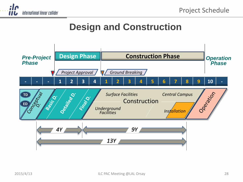
Installation
Project Approval
Operation Phase
- - - 1 2 3 4 1 2 3 4 5 6 7 8 9 10 -
Underground Facilities
Surface Facilities Central Campus
ED
TD
Pre-ProjectPhase
Design Phase Construction Phase
Ground Breaking
Construction
9Y4Y
13Y
Design and Construction
Project Schedule
2015/4/13 ILC PAC Meeting @LAL Orsay 28
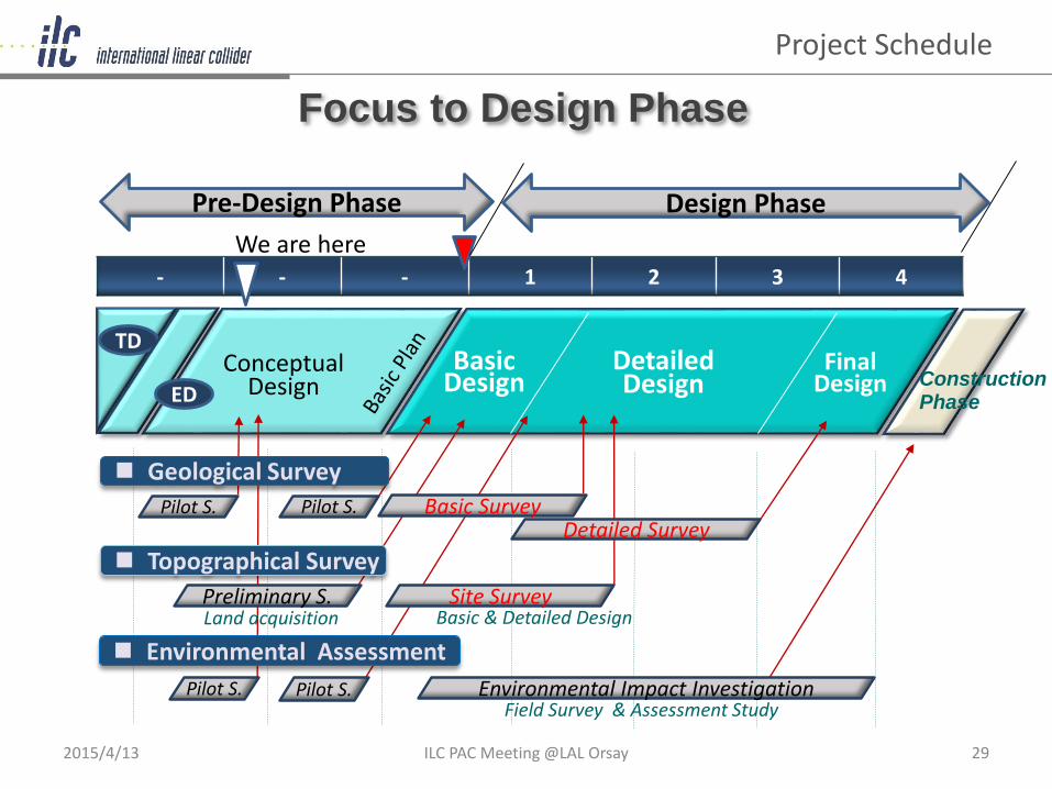
Focus to Design Phase
- - - 1 2 3 4
Detailed Design
TDBasic
DesignConceptual
DesignFinal
DesignED
Design PhasePre-Design Phase
ConstructionPhase
Pilot S. Environmental Impact Investigation Field Survey & Assessment Study
Pilot S.
Land acquisitionSite Survey
Basic & Detailed DesignPreliminary S.
Pilot S.Detailed Survey
Pilot S. Basic Survey
Topographical Survey
Environmental Assessment
Geological Survey
We are here
2015/4/13 ILC PAC Meeting @LAL Orsay 29
Project Schedule

ARUP Work
TOT carries out :• Data analytics to create a set of summary
outputs and visual decision aids.• Series of analytics to give a range of
Optimum Access tunnel positions onto a fixed LINAC position
From the report/John Osborne(CERN) in FCC-Week 2015
Reference: TOT on the FCC ProjectTOT Development on the ILC CFS
TOT: Tunnel Optimization Tool
User defined Input : • ILC main alignment information and
access tunnel positions in 3D space.• Sets of Requirements for Access tunnel/
portal locations to achieve
Status of Contract: CERN & KEK• On going the contract procedure
next steps
2015/4/13 ILC PAC Meeting @LAL Orsay 30

ILC & TOT
CERN & Arup will work with KEK & ILC to upgrade and adapt the Tunnel Optimisation Tool to provide the same benefits for the ILC tunnel that have been brought to the FCC feasibility study
31John Osborne (CERN-GS)
From the CERN-GS Report of FCC Week 2015 at Washington
ILC PAC Meeting @LAL Orsay

CFS Plans for work over the Upcoming 6 months
• Optimization of Horizontal Access Tunnels (CR-03 & 04)• Geological Investigation at IP area in new baseline
- with in-kind regional contribution by Tohoku Univ. and Iwate Prefecture
• CFS Workshop in July 2015 (London or CERN)- Cooperative work with CERN and ARUP for preparing for
the layout optimization software. - Global discussion of Cryogenics scheme change
Response of the Future Change Requests
• Revision of Main Linac Tunnel Configuration (ML Length and Radiation Shield-wall thickness impact )
• Revision of the BDS Tunnel configuration• Revision of the Utility Cavern with Cryogenics scheme change
Next Steps
next steps
2015/4/13 ILC PAC Meeting @LAL Orsay 32

The End
2015/4/13 ILC PAC Meeting @LAL Orsay 33