conventional facilities - fermilab
TRANSCRIPT

Steve Dixon
DOE Independent Project Review of PIP-II
15 November 2016
Conventional Facilities

• PIP-II Associate Project Manager for Civil Construction
• Relevant Experience
– Licensed Architect;
– Project Management Professional (PMP);
– LEED Accredited Professional;
– 24+ years at Fermilab;
– NOvA Project L2 Manager for Site and Buildings;
– General Plant Project Manager
• Short Baseline Neutrino (SBN) Near Detector Building;
• Short Baseline Neutrino (SBN) Far Detector Building;
• CDF Refurbishment;
• Experimental Operations Center;
•
Steve Dixon
11/15/2016S. Dixon | DOE IPR2
Charge Item: #4

• Construction Phase Scope of Work
• R&D Phase Goals
• R&D Status
• R&D Schedule to Complete
• IIFC Interface
• Summary
Outline
11/15/2016S. Dixon | DOE IPR3

• Conventional Facilities to Support PIP-II:
– Site Work
• Utilities (electrical, communication, ICW, DWS, sanitary, chilled water);
• Site Improvements (roads, parking area, hardstands, tank foundations);
– Linac
• Below Grade Enclosure;
• Linac Service Building;
– Transport Line
• Transport Line Enclosure;
• Beam Absorber Enclosure;
• Connection to existing Booster;
– Cryo Plant Building
– Mechanical Plant
Construction Phase Scope of Work
11/15/2016S. Dixon | DOE IPR4
Charge Item: #2

• Conceptual Design:
– Conceptual Design Report Text;
– Conceptual Design Drawings;
• Life Safety Analysis
• Support Analysis of Alternates
• Support NEPA Process
• Prepare for CD-1
– R&D Phase resource loaded schedule
– Construction Phase resource loaded schedule
• Prepare for CD-2/3a
– Advanced Preliminary Design for Site Prep work
– Advanced Preliminary Design for Cryo Plant Building
R&D Phase Goals
11/15/2016S. Dixon | DOE IPR5
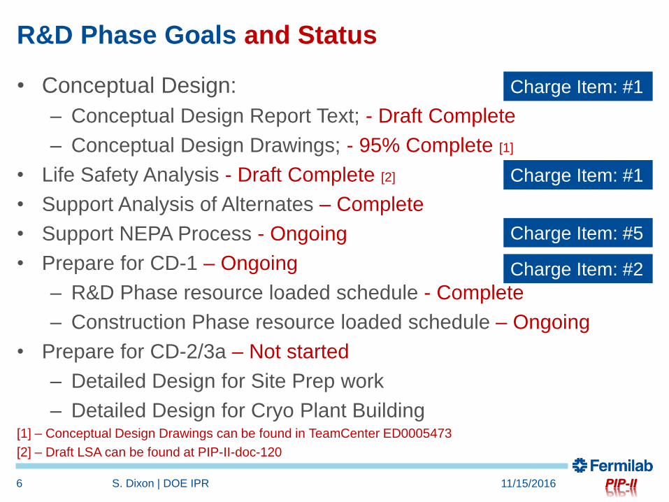
• Conceptual Design:
– Conceptual Design Report Text; - Draft Complete
– Conceptual Design Drawings; - 95% Complete [1]
• Life Safety Analysis - Draft Complete [2]
• Support Analysis of Alternates – Complete
• Support NEPA Process - Ongoing
• Prepare for CD-1 – Ongoing
– R&D Phase resource loaded schedule - Complete
– Construction Phase resource loaded schedule – Ongoing
• Prepare for CD-2/3a – Not started
– Detailed Design for Site Prep work
– Detailed Design for Cryo Plant Building[1] – Conceptual Design Drawings can be found in TeamCenter ED0005473
[2] – Draft LSA can be found at PIP-II-doc-120
R&D Phase Goals and Status
11/15/2016S. Dixon | DOE IPR6
Charge Item: #1
Charge Item: #1
Charge Item: #5
Charge Item: #2

• Meetings with Stakeholders:
– Goal: Document the spatial and infrastructure requirements for
PIP-II facilities;
– Started in January 2016;
– Product was the Conceptual Design drawings and text;
• Results:
– Developed cooling strategies for pulsed mode and continuous
wave operation;
– Conventional facilities are similar to typical Fermilab
construction;
– Backup material has additional details
Conceptual Design Process
11/15/2016S. Dixon | DOE IPR7

R&D Status – Overview
11/15/2016S. Dixon | DOE IPR8
Cryo Plant Utility Building
Linac
Transport Line
Booster
Beam Absorber

R&D Status – Siting Considerations
11/15/2016S. Dixon | DOE IPR9
Site Plan with Possible Future Expansion
Existing Utilities and Services
Accommodating Future Expansion:• Siting;• Space in Linac for additional cryomodules;• Stub for Linac extension;• Stub for beamline to Muon Campus;• Location of Cryoplant• Size of Linac Enclosure (ongoing)

R&D Status
11/15/2016S. Dixon | DOE IPR10
Looking Southeast From Wilson Hall
AZero Service Building
Tevatron Enclsoure Berm
Surface Building Massing
Looking South Along Beamline
White Flags = Warm ComponentsBlue Flags = Cold Components

R&D Status
Typical Linac Cross Section
11/15/201611 S. Dixon | DOE IPR
Cryo Zone
1’-10”Aisle
1’-10”Aisle
RF Zone
LCW Zone

R&D Status – Linac Plan
11/15/2016S. Dixon | DOE IPR12
Cross Section Looking South at Waveguide Penetrations Cross Section Looking South at Coax Penetrations
Public Participation: Viewing Gallery

R&D Status – Main Ring/Transport Line
11/15/2016S. Dixon | DOE IPR13

R&D Status – Transport Line/Booster
11/15/2016S. Dixon | DOE IPR14
Looking Northeast Towards Booster Tower East
Excavation Plan at Booster Tower East
Booster Tower West Shielding Upgrade - 1998

R&D Status – Cryo Plant
11/15/2016S. Dixon | DOE IPR15
Warm Compressor Station
Cold Box Station
Tank Farm
Risk: Cryoplant induced ground motion and superconducting cavity detuning. LCLS-II Engineering Note [3] recommended distance (30m) and isolated foundations for compressors.
[3] – Engineering Note LCLSII-4.8-EN-0326-R0 can be found at PIP-II-doc-122
68
m (
22
5’)
Dis
tan
ce t
o L
inac

R&D Status – Utility Building
11/15/2016S. Dixon | DOE IPR16
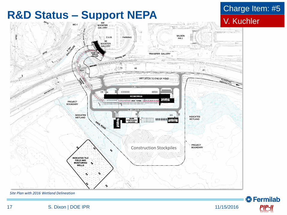
R&D Status – Support NEPA
11/15/2016S. Dixon | DOE IPR17
Site Plan with 2016 Wetland Delineation
Charge Item: #5
Construction Stockpiles
V. Kuchler

R&D Phase Schedule to Complete
11/15/2016S. Dixon | DOE IPR18
FY17:Select an Architect/Engineer;
– Update the drawings;
– Refine cost estimate;
FY18:Begin Detail Design for Site Prep package
FY19 : Final Design begins (includes Site Prep)

• Accommodate the cryo plant equipment
• Interface is with Cryogenics Department (Arkadiy)
IIFC Interface
11/15/2016S. Dixon | DOE IPR19
Charge Item: #4

• Technical Design is based in iterative discussions and meetings with
stakeholders and the conceptual design of the conventional facilities can
meet the specified technical performance requirements;
• The scope of the conceptual design for the conventional facilities is
sufficiently well defined to support the preliminary cost and schedule
estimates;
• The cost estimate will be refined in the coming month as part of the early
tasking of the architect/engineer (A/E);
• To date, the conventional facilities portion has been accomplished by a
combination of in-house staff supplemented with consultants. This effort
will continue with an A/E firm in FY17;
• Conventional facilities has been involved with ES&H activities to date and
will continue to be in the coming stages;
• The IIFC interface for the conventional facilities is primarily the cryo plant
and this interface is well defined;
Summary
11/15/2016S. Dixon | DOE IPR20

Backup Material
11/15/2016S. Dixon | DOE IPR21

Stakeholders:
Fermilab:
Alessandro Vivoli, Anindya Chakravarty, Anthony F Leveling, Arkadiy L Klebaner
Beau F. Harrison, Curtis M. Baffes, David E Johnson, David W Peterson
Don Cossairt, Donald V Mitchell, Emil Huedem, Jim Niehoff, Fernanda G Garcia
Jerry R Leibfritz, Jerzy Czajkowski, John E Anderson Jr, Luisella Lari
Matthew Quinn, Maurice Ball, Paul Derwent, Ralph J Pasquinelli
Todd M Sullivan, Valeri A Lebedev, William A Pellico
Consultants:
Tom Lackowski, TGRWA
Ron Jedziniak, LG Associates
Rick Glenn, Jensen Hughes
11/15/2016S. Dixon | DOE IPR22

Meeting Minutes (PIP-II-doc-70)
• 01 - Coordination Meeting - 17FEB16 (pdf)
• 02 - Cryogenic Department Meeting 19FEB16 (pdf) – Cryo Meeting
• 03 - Coordination Meeting - 02MAR16 (pdf) – Linac Enclosure
• 04 - Coordination Meeting - 09MAR16 R1 (pdf) – Linac Enclosure and Cooling
• 05 - Coordination Meeting - 24MAR16 R1 (pdf) – Linac Enclosure and Cryo Plant
• 06 - Cryo Coordination Meeting - 01APR16 (pdf) – ICW Cooling and Cryo
• 07 - Coordination Meeting - 14APR16 (pdf) – Penetrations and Cooling Strategy
• 08 - Coordination Meeting - 28APR16 (pdf) – Cooling Strategy
• 09 - Coordination Meeting r1 - 12MAY16 (pdf) – Shielding and Transport Line
• 10 - Coordination Meeting - 09JUN16 (pdf) – Shielding Summary
• 11 - Coordination Meeting - 07JUL16 (pdf) – RF Distribution and LCW Cooling
• 12 - Coordination Meeting - 21JUL16 (pdf) – High Bay Equipment
• 13 - Coordination Meeting - 04AUG16 (pdf) – Cryo Summary and Linac Gallery
• 14 - Coordination Meeting - 15SEP16 (pdf) – Sitewide Electrical Distribution
11/15/2016S. Dixon | DOE IPR23

Drawings (TeamCenter ED0005473)
11/15/2016S. Dixon | DOE IPR24
54 Drawings
• One (1) General sheet
• Six (6) Civil sheets
• Forty-Three (43) Architectural sheets
• Three (3) Mechanical sheets
• One (1) Electrical sheet

Typical Design Basis Sheet
11/15/2016S. Dixon | DOE IPR25

Preliminary Shielding Considerations
11/15/2016S. Dixon | DOE IPR26
6’17.5’ 7.5’18.5’18.5’(transport line and absorber)
Preliminary Shielding Depths shown below. Further analysis required, especially at the Booster.
Thanks to D. Cossairt, T. Leveling and M. Quinn
Used the 10W/m curve for the conceptual design

Cryo Plant
11/15/2016S. Dixon | DOE IPR27
Warm Compressor Station
Cold Box Station
Tank Farm

Cryo Plant
11/15/2016S. Dixon | DOE IPR28

Cryo Plant Cooling Requirements
• Water Requirements
– 1,200 – 1,500 gpm flow
• Pond System
– Chemical characteristics met by Pond system;
– Solids content characteristics NOT met by Pond system;
– No Pond - ~$500-$700k per acre;
• ICW System
– Chemical characteristics met by existing ICW system;
– Solids content characteristics NOT met by ICW system;
– Sampling ICW;
11/15/2016S. Dixon | DOE IPR29

Cryo Plant – Water Quality Requirements
11/15/201630 S. Dixon | DOE IPR
Thanks to A. Klebaner and A. Chakravarty

Cryo Plant – Water Quality Test Stand
11/15/201631 S. Dixon | DOE IPR
BZero Compressor Building
• Installed as part of the Mu2e Cryo work for CDF;
• Installed test ports to sample the ICW before and after the strainer;
• Includes a Adams strainer with “standard” slot sizes (baseline);
• Two month rental of a Lakos strainer to reduce the solids;
• Replacement filter elements in Adams strainer with smaller slot size;
• Arranged for FESS/O water testing service to increase the testing to include solids;
• Scheduled testing on same duration as CUB;
• Compare strainer options with water quality requirements.
Strainer
Port for Rental StrainerPort for Rental Strainer

PM vs. CW Considerations
• Driven by duty factor of the equipment
– 15% for Pulsed Mode
– 100% for Continuous Wave Mode
• Common For Both Modes
– Physical arrangement of heat producing equipment;
– Electrical power supply (not usage);
– Conventional Facilities handles the heat load to air (HLA);
• Difference is Primarily Cooling
– 5.0 mw in pulsed mode;
– 10.5 mw in continuous wave mode;
11/15/2016S. Dixon | DOE IPR32

PM vs. CW Considerations - Cooling
11/15/2016S. Dixon | DOE IPR33
Heat Loads
Pulsed Mode
(MW)
Continuous
Wave Mode
(MW)
Low Conductivity Water (LCW) 1.65 7.07
Cryoplant Cooling (Cryo) 3.4 3.4
Total (MW) 5.05 10.47
Industrial Cooling Water (ICW) Cooling Ponds (PW) Towers (close) Towers (open)
Pu
lse
d M
od
e MW to GPM Conversion 682.79 MW to Acres Conversion 800kw/acre
LCW 1,125 gpm LCW 1.98acres LCW 1.0 towers LCW 1.0 towers
Cryo 1,400 gpm @17 Fdt Cryo 4.08acres Cryo 2.0 towers Cryo 1.0 towers
2,525 gpm 6.06acres 3.00 towers 2.00 towers
exclude standby exclude standby
CW
Mo
de
MW to GPM Conversion 682.79 MW to Acres Conversion 800kw/acre
LCW 4,827 gpm LCW 8.48acres LCW 4.0 towers LCW 2.0 towers
Cryo 1,400 gpm @17 Fdt Cryo 4.08acres Cryo 2.0 towers Cryo 1.0 towers
6,227 gpm 12.56acres 6.00 towers 3.00 towers
exclude standby exclude standby
Other Considerations Other Considerations Other Considerations Other Considerations
Strainers, Drought Conditions Strainers, Heat Exchangers, Treatment Heat Exchangers, Treatment, Make Up Heat Exchangers, Treatment, Make Up
Drought Conditions Building Costs Building Costs
Note: 1,400 gpm is the highest flow currently available from the existing ICW system
Thanks to E. Huedem
Basis for Estimate

Cooling Design Approach
• Goal: Modular approach that allows for efficient operation in
both modes;
• Pulsed Mode
– Heat Load to Air (HLA): Utilize chilled water from existing CUB
for equipment cooling (this utilizes the available headroom at
CUB);
– LCW: (1) Cooling tower
– Cryo: (2) Cooling towers
• Continuous Wave Mode
– Heat Load to Air (HLA): Install a chilled water loop to
supplement the pulsed mode system with (2) cooling towers;
– LCW: Add (1) Cooling tower
– Cryo: No change
11/15/2016S. Dixon | DOE IPR34

PIP-II Utility Building
11/15/201635 S. Dixon | DOE IPR
7 Towers:
HLA: 0 in PM, 2 for CW
LCW: 1 for PM, 2 for CW
Cryo: 2 for both modes
N+1 Standby: 1
Separate Piping Runs
For PM and CW modes

Mechanical Conceptual Design
11/15/2016S. Dixon | DOE IPR36

MV Electrical Conceptual Design
11/15/2016S. Dixon | DOE IPR37