5. conventional facilities
TRANSCRIPT
CHAPTER 5
Conventional Facilities
Contents
5.1 Introduction . . . . . . . . . . . . . . . . . . . . . . . . . . . . . . . . . . . 255
5.2 Site Layout . . . . . . . . . . . . . . . . . . . . . . . . . . . . . . . . . . . . 256
5.2.1 Underground Tunnels . . . . . . . . . . . . . . . . . . . . . . . . . . . . . . 256
5.2.2 Surface Facilities . . . . . . . . . . . . . . . . . . . . . . . . . . . . . . . . . 258
5.3 Tunnel Layout . . . . . . . . . . . . . . . . . . . . . . . . . . . . . . . . . . 259
5.3.1 Main Tunnels . . . . . . . . . . . . . . . . . . . . . . . . . . . . . . . . . . . 259
5.3.2 Access Tunnels . . . . . . . . . . . . . . . . . . . . . . . . . . . . . . . . . . 261
5.3.3 Utility Tunnels . . . . . . . . . . . . . . . . . . . . . . . . . . . . . . . . . . 261
5.3.4 Experiment Hall . . . . . . . . . . . . . . . . . . . . . . . . . . . . . . . . . 261
5.3.5 Substations . . . . . . . . . . . . . . . . . . . . . . . . . . . . . . . . . . . . 263
5.3.6 Access Hall . . . . . . . . . . . . . . . . . . . . . . . . . . . . . . . . . . . . 263
5.3.7 Beam Dump Halls . . . . . . . . . . . . . . . . . . . . . . . . . . . . . . . . 264
5.3.8 Tunnel Boring Method . . . . . . . . . . . . . . . . . . . . . . . . . . . . . . 264
5.4 AC Power Distribution . . . . . . . . . . . . . . . . . . . . . . . . . . . . . 266
5.4.1 System Overview . . . . . . . . . . . . . . . . . . . . . . . . . . . . . . . . . 266
5.4.2 Components within the AC Distribution System . . . . . . . . . . . . . . . 266
5.5 Cooling Water and Air Conditioning . . . . . . . . . . . . . . . . . . . . . 269
5.5.1 Cooling Water System . . . . . . . . . . . . . . . . . . . . . . . . . . . . . . 269
5.5.2 Air-Conditioning System . . . . . . . . . . . . . . . . . . . . . . . . . . . . 270
5.5.3 Draining System . . . . . . . . . . . . . . . . . . . . . . . . . . . . . . . . . 271
253

254 Chapter 5. Conventional Facilities
5.6 Information Network and Safety Systems . . . . . . . . . . . . . . . . . . 273
5.7 Process for Construction . . . . . . . . . . . . . . . . . . . . . . . . . . . 274
GLC Project Report, 2003

5.1. Introduction 255
5.1 Introduction
This section discusses the issues associated with the conventional facilities required for GLC. Themajor parts of the conventional facilities for GLC include long tunnels to accommodate the linearaccelerators (linacs) and the experiment halls where the detectors are to be installed. Fig. 5.1 showsa bird’s-eye view of the GLC site in its vicinity of the experiment halls and the campus. In addition,the linear-collider system demands special considerations on numerous utility facilities, such as: thepower supplies, cooling, air conditioning, draining, accident prevention, safety and fire fighting. Theirsystem designs, together with the construction sequence and scheduling, are also discussed. Thestudies and design have been conducted with close cooperation with companies in various fields, suchas civil engineering, facility design, electric-power and cooling systems.
Figure 5.1: Bird’s-eye view of the GLC site. The laboratory campus on the surface is shown.
Underground experiment halls and part of the accelerator tunnels are also shown.
GLC will be operated at an initial center-of-mass energy of up to 500 GeV. However, since the upgradeprogram up to, or beyond, 1 TeV is part of the project plan, the critical elements of the conventionalfacilities need to be able to cope with the possible highest beam energy without major re-engineering.Consequently, it is assumed that the main tunnels will have a total length of ∼30 km. Likewise,
GLC Project Report, 2003

256 Chapter 5. Conventional Facilities
the present baseline plan assumes that the entire set of facility equipment for supporting 1 TeVoperation, such as AC power distribution, cooling water and air conditioning, be installed during theinitial stage construction.1 Since the number of active RF and magnetic elements will depend on thecollision energy, the actual number of active cooling towers and power substations will vary, dependingon the collision energy.
The detailed structure and the construction methods of the accelerator tunnels and the experimenthalls are subject to changes, depending on site where the facility is built. Especially, a general featureof the underground composition, such as soil or bedrock, affects the optimal design of the facility.However, the designs of most of the auxiliary systems and the infrastructures presented here shouldbe applicable to any site location. General features of the site candidates are found in Chapter 6.
As discussed in Chapters 4 and 6, a number of criteria have been devised for the construction siteof GLC. One of the important issues is the stability of the ground, since many elements of theGLC accelerator system require unprecedented accuracy and stability of their alignment, comparedto accelerators in the past. For the studies of conventional facilities presented in this Chapter, theGLC construction site is assumed to be in an area with a bedrock, which is considered to be mostadvantageous from the viewpoint of ground motion.
5.2 Site Layout
5.2.1 Underground Tunnels
Fig. 5.2 shows a schematic diagram of the underground tunnels. The tunnels are subdivided into thefollowing five sections:
System Area Length1. Electron injector system from electron gun 1.7 km
to bunch compressor 22. Electron main linac (including the diagnostics section and bypass) 14.1 km3. Final focus section (including the experiment halls) 1.9 km ×24. Positron main linac (including the diagnostics section and bypass) 14.1 km5. Positron injector system including the electron linac, 2.3 km
positron production target,up to bunch compressor 2
1On the other hand, as for beamline components such as, RF power sources, accelerator structures, waveguides,
focusing magnets and beam monitors for the main linacs, only approximately half of them will be installed for supporting
initial operation at ECM = 500 GeV.
GLC Project Report, 2003
5.2. Site Layout 257
MB
1M
B2
MB
3M
B4
MB
5M
B6
MB
7M
B8
MB
9'M
B9
MB
10M
B11
MB
12M
B13
MB
14M
B15
MB
16M
B1 7
UT
10U
T9
UT
8U
T7
UT
6U
T5
UT
5U
T4
UT
3U
T2
UT
1A
T1
AT
2A
T3
AT
4'A
T5
AT
6A
T7
AT
4
EH
EH
AH
AH
AH
AH
AH
AH
Acc
eler
ator
Tunn
el
1.7
km7.
2 km
6.9
km3.
8 km
36 k
m
6.9
km7.
2 km
2.3
km
Inje
ctor
Mai
n Li
nac
Fin
al F
ocus
sys
tem
Mai
n Li
nac
Inje
ctor
e+e-
PLA
N V
IEW
ELE
VA
TIO
N V
IEW
Cen
tral
Pow
er S
tatio
nS
urfa
ce b
uild
iings
AT:
Acc
ess
tunn
el (
also
for
utili
ty)
UT:
Util
ity tu
nnel
MB
: Pla
nt b
uild
ings
(c
oolin
g, v
entil
latio
n)E
H: E
xper
imen
tal H
alls
AH
: Acc
ess
Hal
ls
Kly
stro
n Tu
nnel
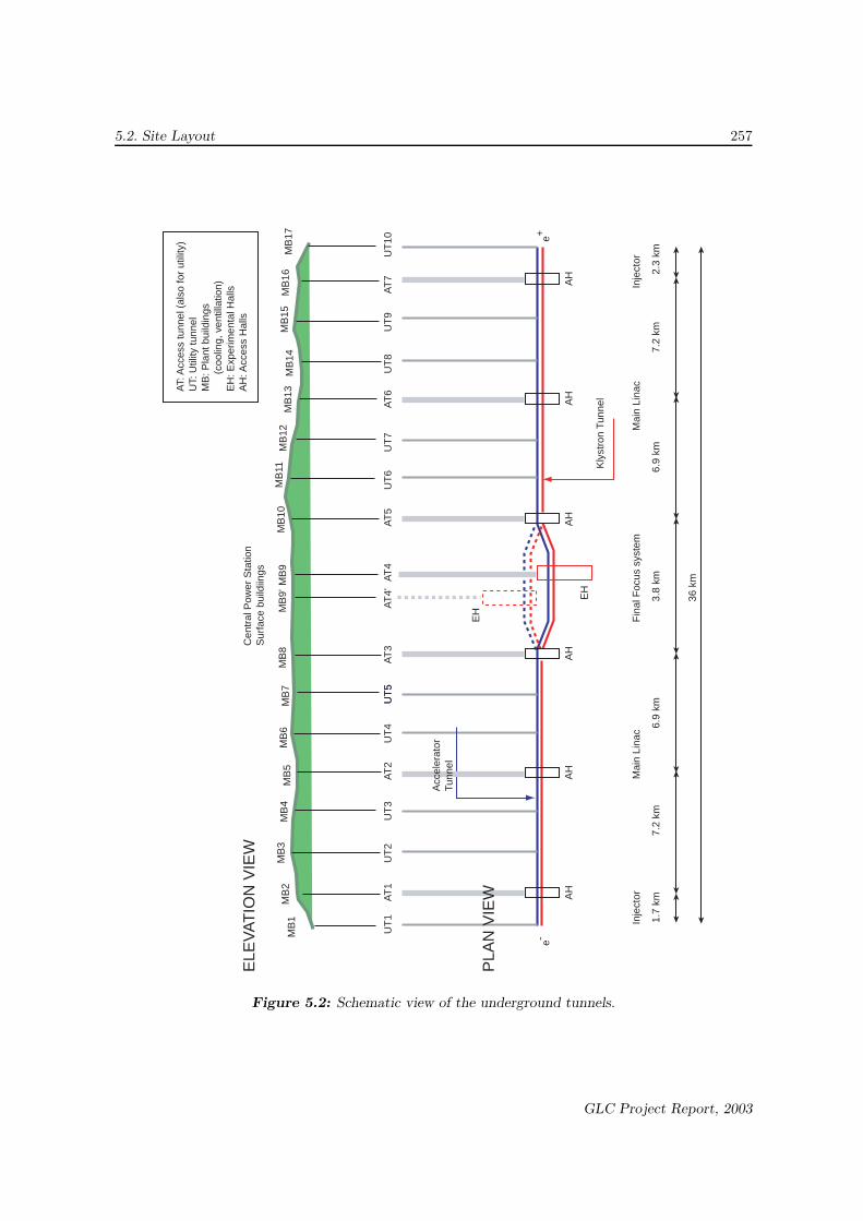
Figure 5.2: Schematic view of the underground tunnels.
GLC Project Report, 2003
258 Chapter 5. Conventional Facilities
The present baseline design of GLC has a single section for electron-positron collisions, with provisionfor two collision points for running two experiments alternatively as an option. In this optional scheme,two experiment halls will be provided and the tunnels for the final focus section will accommodatetwo sets of beamlines for each of the electron and positron parts.
The total length of the beamline in the underground sections amounts to ∼ 36 km. Among the sections,injector systems for electron and positron beams are installed in tunnels with complex structures ateither ends of the site, as described in Chapter 4. Other sections are housed in almost straight tunnelsrunning between both ends of the site. All systems will be constructed so as to fit in about a 33 kmlong site area.
While the subterranean depth changes considerably depending on the site, it is generally assumed tobe several tens to 200 m between the underground and surface facilities. As described later, most ofthe underground sections will have two tunnels running in parallel. One of them will be used for powersuppliers, such as the modulators, klystrons and data processing or control electronics elements, andthe other for the accelerator structures, focusing magnets and beam instrumentation. This designis the best suited to achieve continuous maintenance of the machine during the running time withsufficient human access for active devices, which will lead to a high integrated luminosity of the beamcollision.
As shown in Fig. 5.2, the accelerator tunnels are intersected by auxiliary tunnels (either mining shafts,inclined shafts or level pits) every ∼ 2 km, which are connected to the ground surface. They are usedfor tunnel access by personnel, as well as routing the cooling water, power and control signal cables.About one third of the auxiliary tunnels are to be used to introduce the boring machines duringtunnel construction, and for the delivery of materials and equipment during installation; these arecalled “Access Tunnels” (AT). The experiment hall is associated with a special access tunnel which willbe used as a path for installing the detector facility. The remainder of the auxiliary tunnels are called“Utility Tunnels” (UT) hereafter. Fig. 5.2 shows that the GLC site plan has ten UTs (UT1–10) andseven ATs (AT1–7), including one for the experiment hall (AT4). When the second colliding sectionis approved to be constructed, there will be one more AT (AT4’) to access an additional experimenthall.
5.2.2 Surface Facilities
Facilities on the ground surface include: a central power station, research laboratory buildings, build-ings for air conditioning apparatus, cooling towers, and others. The central power station and researchbuildings will be built on the central campus, located near the center of the linear accelerator. Coolingstations will be installed at every ∼2 km, corresponding to the access areas for the ATs and UTs.
Provisions must be made to accommodate a large number of visiting scientists and engineers fromaround the world. A transportation terminal, guest houses, and other service facilities for these peopleand their family members, have to be prepared.
An outline of the facilities on the ground considered here is given in Table 5.1. The facilities for
GLC Project Report, 2003

5.3. Tunnel Layout 259
researchers will be gradually expanded during the long-term activities of the project. Here, we listthe current plan for the initial form of the laboratory. The land for the central campus is assumed tobe 250,000 m2 in the current design.
Facility Contents Floor space (m2) NumberMain Power Station Special high voltage power station 800 1
Outside field 5600 1Equipments building Air conditioning for tunnel 1000 17
Outside field 250 17Cooling Facility Cooling towers 1500 17Access Hall Access entrance into the tunnel 200 7Assembly Hall fabrication of accelerator/detector 8000 1Research Building Researchers’ office, Conference hall, 10000 (∼1300 m2×7F) 1
Administration, Bureaucratic office,Security center, Radiation protection,Computing
Hostel Hostels 2500 2
Table 5.1: Summary of the on-site facilities on the ground.
5.3 Tunnel Layout
This section describes the composition and scale of the underground facilities (tunnels and halls) forGLC.
5.3.1 Main Tunnels
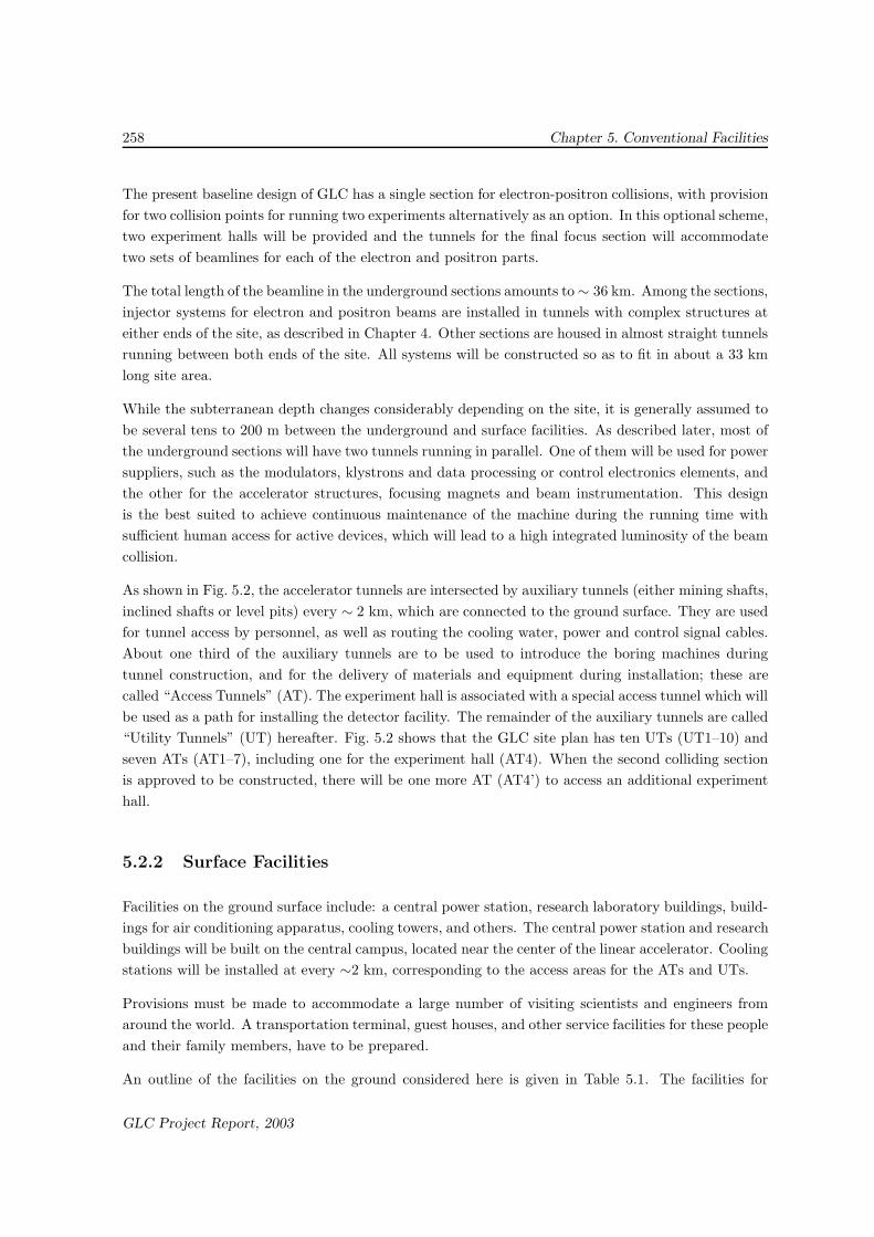
The tunnels for the injector systems, main linacs, and final focus system consist of two parallel tunnels(Main Tunnels). All of these sections have the same double-tunnel structure, while the boring methodwould be different section by section, as described in a later section (see Sec.5.3.8). Fig. 5.3 shows aconceptual view of the double-tunnel structure. The details of the components that are installed ineach of these tunnels are discussed in Chapter 4.
One tunnel has an inner diameter of 3 m for the accelerator structures, vacuum systems, focusingmagnets and beam instrumentation, and is called the “Accelerator Tunnel”. The other tunnel, withan inner diameter of 4.5 m, is for RF power sources (klystrons and modulators) and other powersources for the magnets as well as data-processing electronics circuitry for beam instrumentation, andis called the “Klystron Tunnel.” The use of these two, parallel tunnels for the main linacs stems from
GLC Project Report, 2003
260 Chapter 5. Conventional Facilities
Klystron Tunnel(Inner diameter = 4.5m)
Accelerator Tunnel(Inner diameter = 3m)
KlystronsModulator
SLED-IIdelay lines
Waveguides
AcceleratorStructures
Figure 5.3: Image view of the components installed in the double-tunnel structure of the Main
Tunnels. The Klystron Tunnel (left) houses high-power klystrons and modulators together with
power supplies for the magnets and data-processing electronics circuitry for the beam instrumentation.
The Accelerator Tunnel (right) houses the accelerator structures installed on support girders, which
receive RF power from the klystrons. The beam is accelerated in the Accelerator tunnel, while part
of the Klystron Tunnel may be occupied by support personnel and scientists for repair, diagnosis and
upgrades.
the requirement to allow servicing some of the power source components in the Klystron Tunnel whilecontinuing operation of GLC with accelerator elements that are driven by the remainder of the RFpower sources.
The wall-to-wall separation between the two parallel tunnels is designed to be 5 m (correspondingabout 8.8 m between the centers of the two tunnels). The optimal separation was chosen based onseveral considerations. The most important ones are:
1. The bedrock surrounding the tunnels should be able to maintain sufficient strength. If goodbedrock is assumed where major reinforcement work on the tunnel is considered not to benecessary, the minimum required tunnel separation is roughly 4–5 m.
2. The soil between the two tunnels needs to partially serve as a radiation-shield material. Thisis because the Klystron Tunnel is expected to be, at least momentarily, occupied by service
GLC Project Report, 2003

5.3. Tunnel Layout 261
personnel, while beam operation is taking place in the Accelerator Tunnel. A separation ofabout 2 m is sufficient for this purpose.
Smaller tunnels with an inner diameter of 30 cm will be prepared at every ∼13 m, connecting theKlystron and Accelerator Tunnels. They are used to route the RF power, electric power, signal cablesand cooling water.
5.3.2 Access Tunnels
An Access Tunnel (AT) connects the ground surface to the Main Tunnels or the experiment hall. Itserves as a passage for the people, cooling water, electric power lines, and status and control signalcables for the accelerator. During construction of the facility, the ATs will be used to carry in andout boring machines, such as TBM (Tunnel Boring Machine), and to remove rocks and soils producedin the boring (muck). Seven access tunnels (AT1–7 in Fig. 5.2) will be built along the undergroundfacility.
The length, size and structure of the ATs must be optimized according to the site geometry andaccess roads. An AT could be a level pit, an inclined shaft, a mining shaft, or a combination of those,depending on the ground conditions and road traffic access conditions of the site. In the case of a levelpit or inclined shaft, the inner diameter of the AT would be 6 m. The typical length of the AT withthis scheme is about 500 m, while the length considerably changes point by point and depending onthe site location. The diameter for the AT to an experiment hall is designed to be 15 m, because largedetector facility elements need to be brought in through this AT. Also, if an AT is built as a miningshaft (vertical shaft), its inner radius is required to be larger than 15 m so that a TBM equipmentcan be lowered through it.
5.3.3 Utility Tunnels
Utility tunnels (UTs) also connect the ground surface and the Main Tunnels. However, when GLCis completed, they will be used primarily for routing the cooling water and the power cables. Duringthe construction period, they will also be used for removing the muck that is produced in the boringprocess. The inner diameter of a UT will be about 4 m, suitable for maintenance and servicing.2
There will be ten UTs (UT1–10 in Fig. 5.2).
5.3.4 Experiment Hall
An experiment hall is to be prepared at the collision point of the electron and positron beams. Thesize of the hall in the present design is 85 m× 40 m and 40 m high, sufficiently large for installinga large-scale detector and electronics huts with adequate space for the final assembly of the detector
2Some of the UTs might be enlarged so to have a smooth human access to the underground facilities.
GLC Project Report, 2003
262 Chapter 5. Conventional Facilities
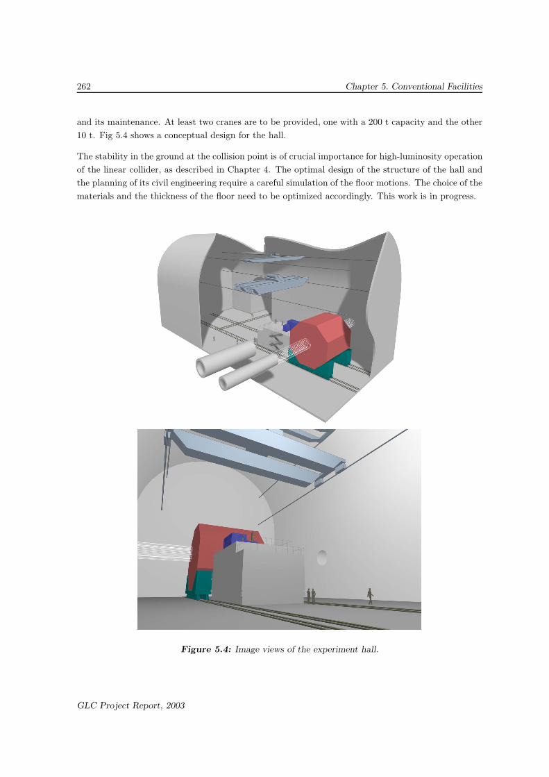
and its maintenance. At least two cranes are to be provided, one with a 200 t capacity and the other10 t. Fig 5.4 shows a conceptual design for the hall.
The stability in the ground at the collision point is of crucial importance for high-luminosity operationof the linear collider, as described in Chapter 4. The optimal design of the structure of the hall andthe planning of its civil engineering require a careful simulation of the floor motions. The choice of thematerials and the thickness of the floor need to be optimized accordingly. This work is in progress.
Figure 5.4: Image views of the experiment hall.
GLC Project Report, 2003

5.3. Tunnel Layout 263
5.3.5 Substations
At some of the knot points of the Access and Utility Tunnels and the Main Tunnels (corresponding toAT1–3, AT5–7, UT2–9 in Fig. 5.2), a hall (substation) for underground utilities will be built. Hence,there will be 14 substations to be prepared in the underground area. Each substation has a 66 kVtransformer to receive electric power from the central power station on the surface, a heat exchangerfor cooling water, and a drainage storage tank, which are described in the following subsections. Thesize of the substation is assumed to be about 500 m2 × 6 m high.
5.3.6 Access Hall
In addition to the substations mentioned above, an Access Hall (AH) will be built at each intersectionof an Access Tunnel (AT1–3 and AT5–7 in Fig. 5.2) and the Main Tunnel, in order to be an under-ground access-control area, a temporary storage area, and so on. A circular dome with a diameter of20 ∼ 25 m is currently being considered, as shown in Fig.5.5. The details of this structure can vary,depending on the type of AT, i.e. whether it is a vertical shaft of a level pit. Within each of the AHs,the main accelerator will be contained in a concrete shield wall.
Figure 5.5: Image view of an access hall.
GLC Project Report, 2003
264 Chapter 5. Conventional Facilities
5.3.7 Beam Dump Halls
Two underground caves will be prepared in order to accommodate the beam dumps (see Chapter 4).These beam-dump halls will be located ∼ 200 m downstream past the collision point for the outgoingelectron and positron beams. The size of each beam dump hall will be about 1500 m2 (60 m long) and15 m height. The size was optimized to cope with the high power of the intense beam to be dumpedwith a sufficient radiation shield during the high-luminosity operation of the collider. The beam is tobe transported for ∼200 m from the collision point to the beam dump through a single tunnel with3m diameter.
In addition to these halls, there will be a few small beam dump areas to be prepared for machineprotection, as described in Chapter 4, at some of the diagnostic sections of the accelerator. A designoptimization is underway.
5.3.8 Tunnel Boring Method
In the case that the construction site is a region with rock bed, the boring method for each tunnel issupposed to be as follows:
• Tunnels for main linac:Both the Accelerator Tunnel and the Klystron Tunnel are sub-divided into four sections alongthe full length. At each end-point, an access hall is prepared for mounting and dismounting theTunnel Boring Machine (TBM). The four sections are bored simultaneously while supplying twoTBM for each section, one for the Accelerator Tunnel and one for the Klystron Tunnel. Hence,eight TBM machines will be used. The boring of the connection tunnel between the AcceleratorTunnel and the Klystron Tunnel, which is necessary for wave guides, will start when about onethird of the Accelerator and Klystron Tunnel is bored. Since the boring work for wave guidesinterferes with the space for the system to transport earth away, the route for transporting theearth away will be changed while utilizing access and utility tunnels in sequence.
• Tunnel for final focus system:The TBM method is supposed to be used. The tunnel is to be bored with one TBM for theAccelerator Tunnel and another TBM for the Klystron Tunnel, in a manner similar to that forthe tunnels for the main linacs.
• Tunnel for pre-accelerators:While the double-tunnel structure is the same as that for the main linacs and the final focussystem, boring with TBM is expected not to be optimal for the pre-accelerator sections, such asa damping ring, because of the curvature of the tunnel. The New Austrian Tunneling method(NATM) is assumed to be used.
• Experiment hall:NATM is assumed to be used. A large area underground hall is usually constructed in two
GLC Project Report, 2003
5.3. Tunnel Layout 265
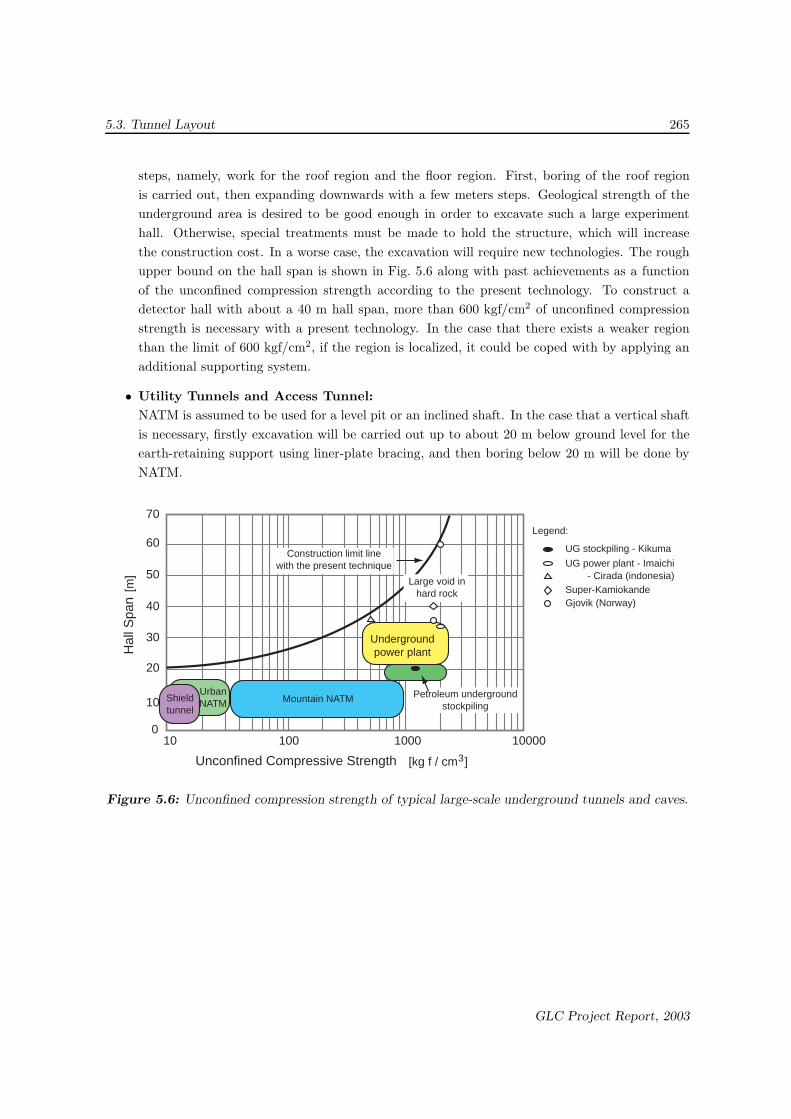
steps, namely, work for the roof region and the floor region. First, boring of the roof regionis carried out, then expanding downwards with a few meters steps. Geological strength of theunderground area is desired to be good enough in order to excavate such a large experimenthall. Otherwise, special treatments must be made to hold the structure, which will increasethe construction cost. In a worse case, the excavation will require new technologies. The roughupper bound on the hall span is shown in Fig. 5.6 along with past achievements as a functionof the unconfined compression strength according to the present technology. To construct adetector hall with about a 40 m hall span, more than 600 kgf/cm2 of unconfined compressionstrength is necessary with a present technology. In the case that there exists a weaker regionthan the limit of 600 kgf/cm2, if the region is localized, it could be coped with by applying anadditional supporting system.
• Utility Tunnels and Access Tunnel:NATM is assumed to be used for a level pit or an inclined shaft. In the case that a vertical shaftis necessary, firstly excavation will be carried out up to about 20 m below ground level for theearth-retaining support using liner-plate bracing, and then boring below 20 m will be done byNATM.
Moun
70
60
50
40
30
20
10
010 100 1000 10000
[m]
Hal
l Spa
n
[kg f / cm ]3Unconfined Compressive Strength
Construction limit linewith the present technique
Large void inhard rock
Undergroundpower plant
Mountain NATMUrbanNATMShield
tunnel
Petroleum undergroundstockpiling
UG stockpiling - Kikuma
UG power plant - Imaichi- Cirada (indonesia)
Super-KamiokandeGjovik (Norway)
Legend:
Figure 5.6: Unconfined compression strength of typical large-scale underground tunnels and caves.
GLC Project Report, 2003
266 Chapter 5. Conventional Facilities
5.4 AC Power Distribution
5.4.1 System Overview
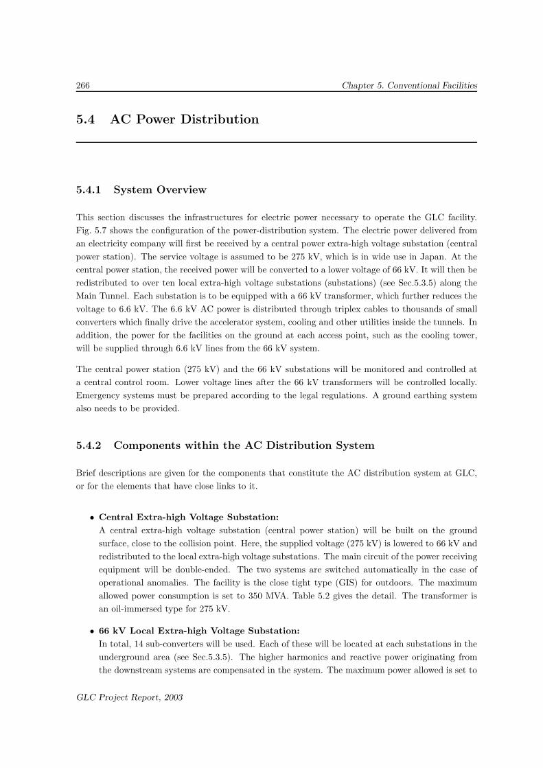
This section discusses the infrastructures for electric power necessary to operate the GLC facility.Fig. 5.7 shows the configuration of the power-distribution system. The electric power delivered froman electricity company will first be received by a central power extra-high voltage substation (centralpower station). The service voltage is assumed to be 275 kV, which is in wide use in Japan. At thecentral power station, the received power will be converted to a lower voltage of 66 kV. It will then beredistributed to over ten local extra-high voltage substations (substations) (see Sec.5.3.5) along theMain Tunnel. Each substation is to be equipped with a 66 kV transformer, which further reduces thevoltage to 6.6 kV. The 6.6 kV AC power is distributed through triplex cables to thousands of smallconverters which finally drive the accelerator system, cooling and other utilities inside the tunnels. Inaddition, the power for the facilities on the ground at each access point, such as the cooling tower,will be supplied through 6.6 kV lines from the 66 kV system.
The central power station (275 kV) and the 66 kV substations will be monitored and controlled ata central control room. Lower voltage lines after the 66 kV transformers will be controlled locally.Emergency systems must be prepared according to the legal regulations. A ground earthing systemalso needs to be provided.
5.4.2 Components within the AC Distribution System
Brief descriptions are given for the components that constitute the AC distribution system at GLC,or for the elements that have close links to it.
• Central Extra-high Voltage Substation:A central extra-high voltage substation (central power station) will be built on the groundsurface, close to the collision point. Here, the supplied voltage (275 kV) is lowered to 66 kV andredistributed to the local extra-high voltage substations. The main circuit of the power receivingequipment will be double-ended. The two systems are switched automatically in the case ofoperational anomalies. The facility is the close tight type (GIS) for outdoors. The maximumallowed power consumption is set to 350 MVA. Table 5.2 gives the detail. The transformer isan oil-immersed type for 275 kV.
• 66 kV Local Extra-high Voltage Substation:In total, 14 sub-converters will be used. Each of these will be located at each substations in theunderground area (see Sec.5.3.5). The higher harmonics and reactive power originating fromthe downstream systems are compensated in the system. The maximum power allowed is set to
GLC Project Report, 2003

5.4. AC Power Distribution 267
275 kV
66 kV ditribution line (14 feeders)
Tr66 kV / 6.6 kV25MVA ~ 30 MVA
G
Filter- SVC
16 - 17 units / feeder
275 kV master substation
66 kV substation
stand-by generator(at each 66 kV substation)
HV transforming units(200 V for Cooling systemin tunnel)3 - 200 kVA
HV transforming units(for mechanical and electrical systems)1 - 50kVA and3 - 200kVA(generator loard)
HV transforming units(400 V for accelerator)3 - 200 kVA
275 kV / 66kV360 MVA x 2
Tr
Generatorload
Generatorload
HV substationfor 66kV substation
HV substationfor surface facility
A service areaof one 66 kV substation
Figure 5.7: Schematic drawing of electric power distribution system.
GLC Project Report, 2003
268 Chapter 5. Conventional Facilities
Items Maximum Allowed CommentsPower Consumption
Main Accelerator 300 MW
Cooling Tower 17 MW 1 MW/unit×17 (surface)Lights and cooling 4 MVA 100 VA/m×36 kmin tunnelAir conditioning system 9 MW 0.5 MW/place×17 (surface)Sub-total 330 MWOther facilities 20 MW Central power station, control, computingGrand total 350 MW
Table 5.2: Maximum power acceptance assumed for operation at ECM = 1 TeV.
25–35 MVA for each 66 kV substation. The secondary voltage is 6.6 kV. Static capacitors areused in the 6 kV main bus-bar to stabilize the subsequent 6.6 kV systems.
• 6.6 kV Transforming System:This system will supply the driving power for the RF power sources (400 V), accelerator coolingsystem (200 V) and other utilities inside the tunnel (200 V single phase). In the current design,the transformers are located under the floor inside the Klystron Tunnel. A simple and smallsystem is used to reduce the space requirement inside the tunnel.
• Main Power Distribution Cables:Twisted cables (Triplex) are used to distribute 66 kV and 6.6 kV in the tunnel. The cabling ismade in the Klystron Tunnel.
• Lighting:The design illuminance of the main facilities is 200 lux for inside the tunnels and 500 lux for thecontrol rooms. In the Accelerator Tunnel, exchangeable parts and materials with less radiationdamage are used to cope with radiation safety. In the Klystron Tunnel, there are no suchlimitations.
• Backup Powers for Emergency:A standby generator of 6.6 kV will be prepared at each 66 kV substation. The standby generatorsare used for water pumps and smoke evacuation as required by the laws. A DC power supplysystem will be prepared for controlling the substations and the emergency lighting system.The distribution of the power takes into account the limitation of the DC line length. A non-interruptible power supply (UPS) will be equipped for the main control system of the powerdistribution system.
GLC Project Report, 2003
5.5. Cooling Water and Air Conditioning 269
5.5 Cooling Water and Air Conditioning
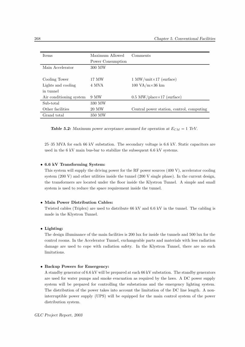
5.5.1 Cooling Water System
Fig. 5.8 shows an outline of the cooling water system and the concept for the divergent cooling unit.A major part of the heat generated in the accelerator complex will be disposed of by a cooling system.The elements within the cooling system include: cooling towers on the ground to cool the primarycooling water, pipes to deliver the water inside the tunnel, heat exchangers between the primaryand secondary water, and a fine temperature-control system for the secondary water which is to beinstalled at each accelerator element.
Ground Surface
1 km2 km
Exp. hall Acceleratortunnel
Heatexchanger
Cooling water unit
Mixer
Bidirectionalvalves x2
Heat load(150 kW)
Klystrons, etc
Acc. structures, etc+/- 0.1 C
56 C
45 C
30 C
54.6 C
40 C
N2
T
Pump station (17 stations, every ~ 2km)
Primary cooling waterfrom air-cooling towers
Figure 5.8: Schematic diagram of the cooling system.
Hermetic air-cooling towers, located at every ∼2 km on the ground, will provide the accelerator withprimary cooling water at 30◦C (outside atmospheric temperature at 25◦). The GLC will have 17towers, each with a cooling capacity of 30 MW.
The temperature tolerance of the supplied primary cooling water is set to be about ±2◦C. The watertemperature returned from the accelerator is about 55◦C. Inside the underground tunnels, the waterline is piped with the reverse-supply scheme, and branched at every 7 m to provide cooling water toeach heat exchanger.
GLC Project Report, 2003

270 Chapter 5. Conventional Facilities
The required fine temperature control and purification of the secondary cooling water will be made bycontrol units dedicated to each device category. Therefore, the quality of the primary water suppliedinto the tunnels may be at the same level as city water, and steel tubes can be used for piping.Since the altitude difference between the ground where the cooling towers are located and the tunnelsmay reach 200 m at maximum, all pipes, valves and shrinkable connectors and other components arerequired to withstand up to 300 kPa of pressure. In the current design, the expansion of the pipesdue to temperature changes, especially at the beginning of operation after a shutdown, is absorbedby a set of connection pipes designed for that purpose.
5.5.2 Air-Conditioning System
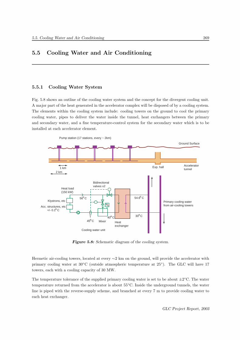
While most of the heat generated in the operation of the accelerator is removed by the cooling-watersystem installed in the accelerator devices, a few percent of the generated heat will spread in the airpassing through heat insulators. A ventilation and air-conditioning system is required to provide thepersonnel and equipment underground with clean air and a suitable air temperature. Fig. 5.9 showsthe concept for tunnel ventilation and the air-conditioning system.
The ventilation and air-conditioning system are designed with the following operational conditions inmind:
• Accelerator Tunnel: circulation rate of ∼ 0.2 times/hour, and low heat generation in the air(negligible), 30◦C max (tolerance not determined).
• Klystron Tunnel: circulation rate of ∼ 0.2 times/hour. Heat generation of ∼ 200 W/m, 30◦Cmax (tolerance not determined).
The outside air is processed with an air-handling unit on the ground surface. The Accelerator andKlystron Tunnels share the same outside air-handling units. An air inlet for the Accelerator andKlystron Tunnels is located every ∼4 km. A Utility Tunnel between the two will serve as an airoutlet. In total, there will be 9 inlet and 8 outlet air-handling units. Each inlet air-handling unitis equipped with an air-cooling heat pump chiller. It cools down the outside air in the summer andwarms up the air in the winter without humidification. This will provide a sufficient air-conditioningcapability inside the Accelerator Tunnel, because heat generation into the air is relatively low there.
As for the Klystron Tunnel, however, the heat generation is relatively high, and there will be frequenthuman access for maintenance of active accelerator elements. Therefore, fan coil units are used forthe air cooling in the Klystron Tunnel, as shown in Fig. 5.9. Cold water for the air conditioningis produced at the cooling stations (equipped with air-source chilling units) located on the groundsurface every ∼2 km, where cooling towers for the primary cooling water also exist.
At each station, the cooling water for the fan coil units is delivered to the underground facilities throughthe Utility and Access Tunnels, as is done for the primary water for the cooling-water system, andprocessed with a heat exchanger. It is then provided to each fan coil unit located every ∼10 m, andthen returned using the reverse return method.
GLC Project Report, 2003
5.5. Cooling Water and Air Conditioning 271
Chiller Unit
Air Handling Unit
Exhaust Fan
HEPA Filter Unit
Heat Exchanger
Klystron Tunnel
Linac Tunnel
Fan Coil Unit
2 km@10m
Figure 5.9: Schematic diagram of the ventilation system.
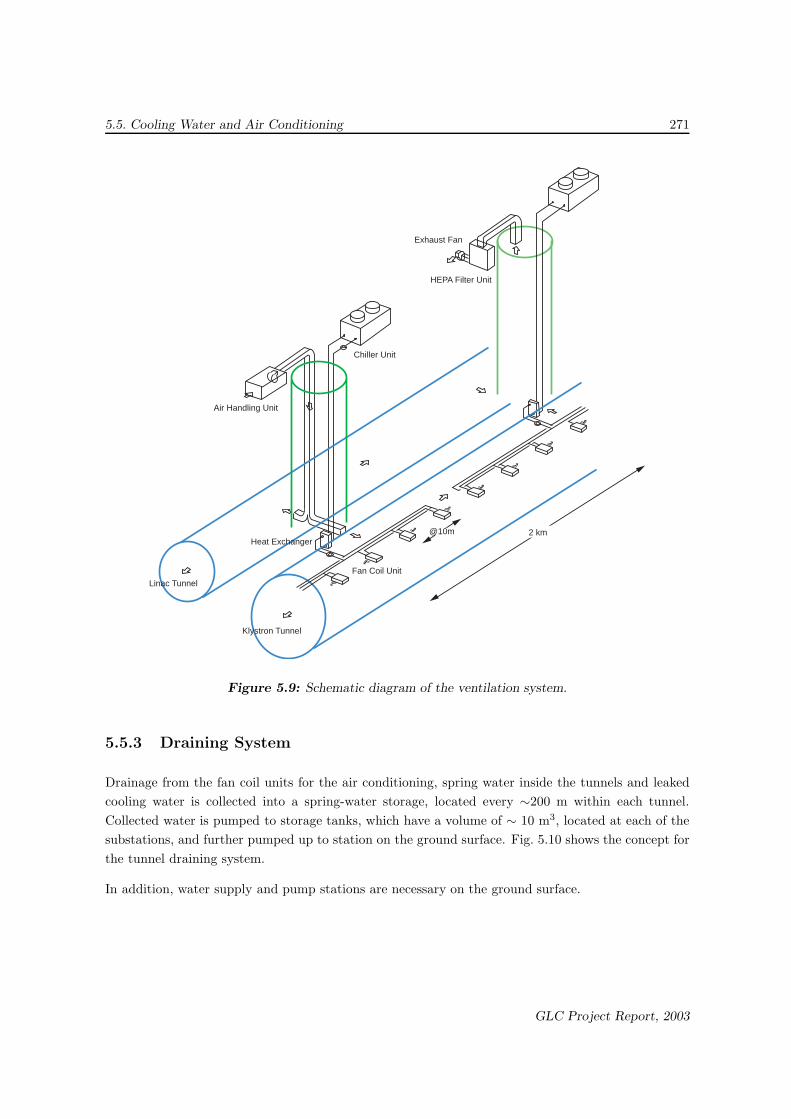
5.5.3 Draining System
Drainage from the fan coil units for the air conditioning, spring water inside the tunnels and leakedcooling water is collected into a spring-water storage, located every ∼200 m within each tunnel.Collected water is pumped to storage tanks, which have a volume of ∼ 10 m3, located at each of thesubstations, and further pumped up to station on the ground surface. Fig. 5.10 shows the concept forthe tunnel draining system.
In addition, water supply and pump stations are necessary on the ground surface.
GLC Project Report, 2003

272 Chapter 5. Conventional Facilities
Klystron tunnel
Pump
Pump
Pump
Storage tank
Linac tunnel Fan coildrain
Leaked cooling water
Spring waterLeaked cooling water
Spring water
Drain
Figure 5.10: Schematic diagram of the drainage system.
GLC Project Report, 2003

5.6. Information Network and Safety Systems 273
5.6 Information Network and Safety Systems
The following items will be prepared for the information network system:
• PHS inside the laboratory and all facilities related to it
• Broadcasting facility
• Checking cameras (one per 50 m inside tunnel)
• LAN cables
• TV cables
These are required to monitor the status of the hardware within the tunnels during operation, aswell as to support the communication between the personnel inside the tunnels and the control centerduring a hardware installation and maintenance period.
Safety systems at GLC must be prepared according to national laws concerning buildings (basicbuilding law) and fire defense. The Main, Access and Utility Tunnels are categorized as “cave roads”,and are not subject to the regulations for buildings nor fire defense (some negotiation with relevantdepartments may be necessary). Therefore, a fire extinguishing system is not required by law, inprinciple. Nevertheless, for self-defense purposes, the experiment hall, the access halls, the transformersubstation halls and the Klystron Tunnel will be equipped with fire-extinguishing systems.
Areas are subdivided into smaller local areas (safety-blocks) so as to be able to immediately deal withany accidents. The situation related to all safety and security issues will be monitored and displayedat the central security control center.
The safety system includes the following:
• Fire-extinguishing system: Since electricity is the most probable source of fire, systems basedon chemical powder are the appropriate choices. The experiment and access halls are equippedwith movable powder fire extinguisher systems or big fire extinguishers. The Main Tunnels arealso equipped with fire extinguishers.
• Fire alarm system: Smoke alarms and thermo-alarms are placed in the tunnels. All informa-tion will be collected by receivers in each safety block.
• Emergency Warning (Broadcasting) system: All areas related to the GLC facility will becovered by a broadcasting system for an emergency. A broadcasting amplifier is to be locatedin each security block. Remote signal from the central system will be delivered through opticalcables.
• Emergency lights: In the case of an emergency, DC electricity will be supplied through eithermain lines or secondary lines.
GLC Project Report, 2003

274 Chapter 5. Conventional Facilities
• Radiation safety: Radiation safety monitors must be equipped appropriately in the KlystronTunnel and the Accelerator Tunnel, as well as the experiment hall. All information will becollected to the central radiation safety system. Access to the radiation-safety areas must befully controlled by both the central and local systems.
• Gas safety: Gas safety systems must be made in the experiment hall.
Attention must be paid to radiation effects in the surroundings of the tunnels during acceleratoroperation. A simulation study has been conducted on this issue for radiation that originates frombeam losses in the main linacs. The assumptions in this simulation included the following: (1) thecenter of 3mφ tunnel is located at least 10 m deep underground, (2) the accelerator structures are setat the tunnel center, (3) the concrete wall of the tunnel is 30 cm thick, (4) the beam power is 8 MW,(5) the beam loss is 0.25%, which is uniformly distributed along the linac of 8900 m length and (6)the annual operation time is 5,000 hours.
It was found that the radiation dose on the surface ground above the tunnel will be 3 µSv/year, evenin the case of relatively shallow tunnels. This estimated radiation dose corresponds to 0.2% of thenatural radioactivity (1 ∼ 2 mSv/year). For deeper tunnels, the surface radiation dose will decreaseexponentially. For example, the expected dose will be 10−5 µSv/year in the case of tunnels that are20 m deep. In addition to beam losses within the accelerators, many muons will be created at thebeam dumps. However, the radiation dose on the surface due to these muons will be substantiallysmaller. Simulation studies indicated that the radiation due to neutrons can be controlled to staywithin a safe level, too. The activation of ground water is required to be lower than 10 µSv/year.This is also considered to be achievable.
In addition, the levels of radiation at the site boundaries will be measured by using monitor stations.The stations will be installed on the ground surface along the accelerator tunnel at intervals of afew kilometers. These monitors will be equipped with a stand-alone power supply based on solarcells and a wireless data-transmission system. This allows continuous monitoring of radiation levelsat locations distant from the main campus without frequent needs for maintenance. The types ofradiation to be measured are neutrons, photons and ionizing particles, such as muons, emitted duringthe operation of the GLC accelerators. The levels of radiations are surveyed online by the NORM(Network of Radiation Monitors) system, which will be newly designed for GLC. These measurementsinclude monitoring the emissions of radioactivity in the air and in the water.
5.7 Process for Construction
The boring speed by TBM is normally 200–500 m/month/TBM machine, which greatly depends onthe underground condition. One finds several examples of the recent boring in a granite rock areain Japan with the boring speed reaching to about 700 m/month. We assume that the condition ofthe construction site is sufficiently good to bore at a speed of 300 m/month/TBM machine. This
GLC Project Report, 2003

5.7. Process for Construction 275
is a reasonable assumption if the site is better than CM-class rock without encountering any majordifficulty, such as a large area of delicate rock which needs subsequent countermeasures, in the boringregions. Once such a condition is satisfied, the tunnel needs only to be sprayed with concrete withoutany additional supporting mechanism in most of the areas inside the tunnel.
An overview on the whole process, from tunnel boring to alignment of the accelerator components, isshown in Fig. 5.11.
The first step of the tunnel boring is the excavation of the Utility and the Access Tunnels from groundsurface to the Main Tunnels. While the duration of the excavation will depend on the length andthe scheme of these tunnels, it will be completed in about a year. Through five out of seven AccessTunnels (AT1 ∼ 3, 5 ∼ 6), the TBM system will be installed and prepared for boring of the MainTunnels. The current plan assumes 10 TBM to be operated simultaneously. At each section of theboring of the Main Tunnel, a pair of TBM will be used for constructing the double-tunnel structure.
The boring process by the TBM will take about two years for the Main Tunnels for the linacs and finalfocus sections. The excavation of the injector systems, mainly with NATM, will also be accomplishedin the same period. As for an experiment hall, it will take about 3 years to complete the excavation.Note that there will be a large amount (> 100 m3) of muck to be produced in the boring process,which will be removed through the Access and Utility Tunnels. Once the boring by TBM is completedfor about a 2 km long section, an AT or UT to be used for muck removal will be switched to thenext one. Then, the boring process for the 30 cm φ bore-holes will follow for the section to connectbetween the Klystron Tunnel and the Accelerator Tunnel. The ways to dispose or recycle the muckmust be planned in detail before construction, which is one of the key elements for a speedy andsteady construction.
A section having all boring procedures completed will be cleaned up. This is for subsequent processesincluding the installation of systems for electric power, cooling water and others. Eventually, when thefloor in the tunnels is ready for the section, hardware devices, such as the accelerator units structure,RF devices and magnets, will be installed. Most of the elements are expected to be placed by theend of the 4th year of the construction period. An initial alignment of the accelerator units will beperformed as described in Chapter 4. It is expected to take 5 years for the overall process of boring,installation, and the initial alignment.
The following additional considerations are necessary to further optimize the design and to shortenthe engineering period:
• Procedure for muck transporting underground and on ground,
• Delivery system for the accelerator components in the tunnel,
• Installation procedures in detail, and
• Optimization of accelerator assembling method.
GLC Project Report, 2003

276 Chapter 5. Conventional Facilities
Year
s
1 2 3 4 5
Acc
ess
Hal
lA
cces
s H
all
Acc
ess
Hal
lA
cces
s H
all
Acc
ess
Hal
lA
cces
s H
all
Exp
. Hal
l
Mai
n lin
ac tu
nnel
7.2
km
Mai
n lin
ac tu
nnel
6.9
km
Mai
n lin
ac tu
nnel
6.9
km
Mai
n lin
ac tu
nnel
7.2
km
FF
s tu
nnel
4.3
km
AT
AT
AT
AT
AT
AT
AT
UT
UT
UT
UT
UT
UT
UT
UT
Exc
avat
ion
of U
tility
tunn
els;
Des
ign,
con
stru
ctio
n an
dde
liver
y of
TB
M.
Exc
avat
ion
of M
ain
tunn
els
(1/3
) ;D
ispo
sal o
f muc
k
Exc
avat
ion
of M
ain
tunn
els
(2/3
);C
onne
ctio
n bo
reho
les
for
the
Mai
n tu
nnel
sS
uppo
rt s
yste
m (
1/3)
Dis
posa
l of m
uck
Exc
avat
ion
of M
ain
tunn
els
(3/3
);C
onne
ctio
n bo
reho
les
for
the
Mai
n tu
nnel
,S
uppo
rt s
yste
m (
2/3)
,D
ispo
sal o
f muc
k
Con
nect
ion
bore
hole
s fo
r th
e M
ain
tunn
els,
Sup
port
sys
tem
(3/
3),
Mai
n tu
nnel
util
ity (
1/2)
Dis
posa
l of m
uck
Lege
nd
Exc
av.
Acc
ess
Hol
es
Util
s F
inis
h
Muc
k D
ispo
sal
Hal
l util
ityM
ain
tunn
el u
tility
(2/
2)A
ccel
erat
ors
Figure 5.11: Construction process.
GLC Project Report, 2003