iepc-93-042 384 hollow cathode heater development for...
TRANSCRIPT
IEPC-93-042 384
HOLLOW CATHODE HEATER DEVELOPMENT FOR THESPACE STATION PLASMA CONTACTOR
George C. Soulas'Sverdrup Technology, Inc.
NASA Lewis Research Center GroupBrook Park. Ohio
Abstract the discharge.' Although it is not anticipated that theplasma contactor will be cycled on and off, the
A hollow cathode-based plasma contactor has contactor emission current to the space plasma willbeen selected for use on the Space Station. During vary throughout the course of an orbit' which willthe operation of the plasma contactor, the hollow impart a cyclic thermal load onto the heater. It iscathode heater will endure approximately 12000 anticipated that the heater will endure approximatelythermal cycles. Since a hollow cathode heater failure 12000 thermal cycles, most of which will occur to anwould result in a plasma contactor failure, a hollow unpowered heater. Without a reliable heater that cancathode heater development program was established withstand these thermal cycles, the plasma contactorto produce a reliable heater design. The development may fail.program includes the heater design, process docu- Ion thrusters also utilize these heaters for thements for both heater fabrication and assembly, and discharge and neutralizer hollow cathodes. The 30-heater testing. The heater design was a modification cm derated xenon ion thruster2 tested at the NASAof a sheathed ion thruster cathode heater. Three Lewis Research Center (LeRC) utilizes the sameheaters have been tested to date using direct current heater as that of the plasma contactor. Near termpower supplies. Performance testing was conducted applications for ion thruster technology include north-to determine input current and power requirements for south station-keeping and on-orbit repositioningachieving activation and ignition temperatures, single missions.' 7 For these missions, it is anticipated thatunit operational repeatability, and unit-to-unit opera- the thruster cathodes will be operated for 3000-4000tional repeatability. Comparisons of performance on-off cycles on large communication satellites totesting data at the ignition input current level for the achieve lifetimes in excess of ten years.'"7 A reliablethree heaters show the unit-to-unit repeatability of heater will be essential to meet these life time require-input power and tube temperature near the cathode tip ments.to be within 3.5 W and 44 *C, respectively. Cyclic Potted heaters, alumina flame/plasma sprayedtesting was then conducted to evaluate reliability heaters, and sheathed heaters have been developed forunder thermal cycling. The first heater, although plasma contactors and ion thrusters. Although alldamaged during assembly, completed 5985 ignition heater types have been successfully tested,-' 0 onlycycles before failing. Two additional heaters were alumina flame/plasma sprayed and sheathed hollowsubsequently fabricated and have completed 3178 cathode heaters were investigated in this programcycles to date in an on-going test. since there was a considerable amount of experience
with these types at LeRC. While aluminaIntroduction flame/plasma sprayed hollow cathode heaters were
successfully flight tested on the SERT II spacecraft.*A hollow cathode-based plasma contactor has a later program, using larger diameter cathodes, re-
been baselined for use on Space Station to reduce vealed that the alumina insulation was prone tostation charging.' The hollow cathode utilized by the cracking after fewer than 1000 thermal cycles, andplasma contactor requires a heater to provide heat to that this cracking typically resulted in a heater fail-1) remove contaminants from the cathode electron ure.' 0 Furthermore, fabrication procedures for alumi-emitting insert surface during activation and 2) ignite na flame/plasma sprayed heaters involved high levels
of skill and attention to detail that exceeded those re-'Aerospace Engineer quired for sheathed heaters." To avoid these prob-
lems, sheathed heaters were utilized. SheathedThis paper is a work of the U.S. Government and is not heaters were shown to operate reliably for thousandssubject to copyright protection in the United States. of on f cycles for both ion thrusters0 and resisto-
of on-off cycles for both ion thrusters" and resisto-
385 IEPC93-042
jets," and were baselined for use on the J-series 30- to the circuit, and the radiation shield reduces radiatedcm mercury ion thruster, an engineering model power losses. The detailed heater design will be dis-thruster for a solar electric propulsion system ground cussed in a later section.demonstration program." The J-series hollow cathode The fabrication procedures were written withheater design, however, suffered from a high failure sufficient detail to ensure repeatability of the assem-rate during acceptance testing and a termination bly process. They include specifications for alldesign that was complex, fragile, and difficult to cleaning, swaging, annealing, welding, and brazingfabricate." processes, as well as the assembly procedures.
For the plasma contactor hollow cathode heater, Inspection procedures were included to ensure suc-the J-series hollow cathode heater design was modi- cessful heater fabrication. These procedures includefled to increase heater reliability. A test program was visual, radiographic, and thermographic inspections,developed to verify reliability under thousands of an insulation compaction measurement, and coldcyclic thermal loads. Heater design, fabrication, and resistance measurements. The heater assemblyinspection procedures were developed. A heater test process includes a record of all material data tofacility that included a computer data acquisition and ensure traceability of heater material, as well as thecontrol system was designed and assembled. Heater implementation of fabrication and inspection proce-testing. which includes performance testing to deter- dures. As a final test of heater unit reliability, anmine power requirements and operational repeatability acceptance testing procedure is conducted. This testand cyclic testing to evaluate reliability, is underway includes a cold heater resistance measurement beforefor several heaters. and after completing a series of on-off cycles.
This paper presents the status of the heater Heater tests for design validation include cyclicdevelopment program for the Space Station plasma testing of the plasma contactor and hollow cathode.contactor. The heater development program is vibrational testing of plasma contactor, and testing ofinitially discussed. Aspects of the experimental the heater unit alone. This paper will focus on theprogram, including the test facility, the heater design, latter. Testing of the heater unit alone includesand the heater test procedures, are then presented. performance testing and cyclic testing. PerformanceFinally, results from heater testing are presented and testing is used to determine input current and powerdiscussed, requirements for achieving activation and ignition
temperatures, single ruit operational repeatability, andHeater Development Program unit-to-unit operational repeatability. Performance
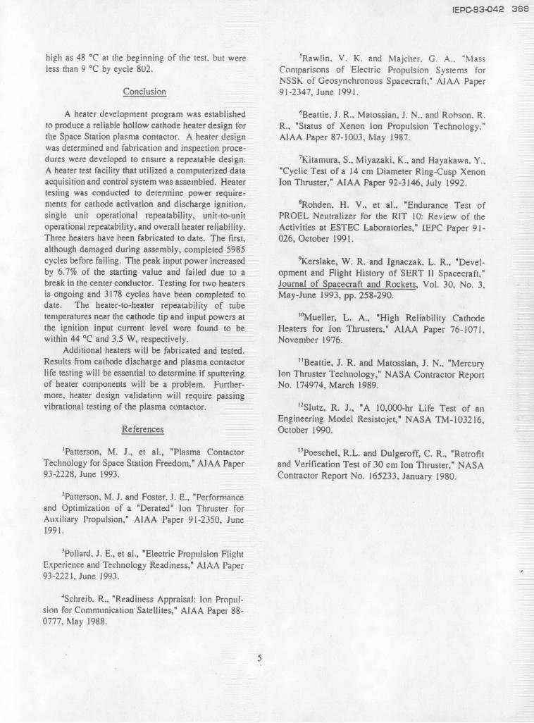
tests are conducted before and after cyclic testing.A flow chart describing the hollow cathode Cyclic testing is used to evaluate heater reliability
heater development program is shown in Fig. 1. The under a cyclic thermal load by subjecting the heaterheater development program was designed to be an to an ion thruster qualification test for a ten year,iterative process between the heater design and north-south station-keeping mission on a large com-process documents, the heater assembly, and heater munication satellite. Using the industry qualificationtesting. The heater design and process documents standard of 1.5 times the maximum number of cy-were based on heater requirements for die plasma cles,4" such a test would require a successful comple-contactor cathode. Following heater assembly, the tion of around 6000 on-off cycles.heaters were tested, and results from these tests wereused to modify the heater design and process docu- Test Apparatusments. The hollow cathode heater design is validatedupon successful completion of all heater testing. Heater Test Facility and Apparatus
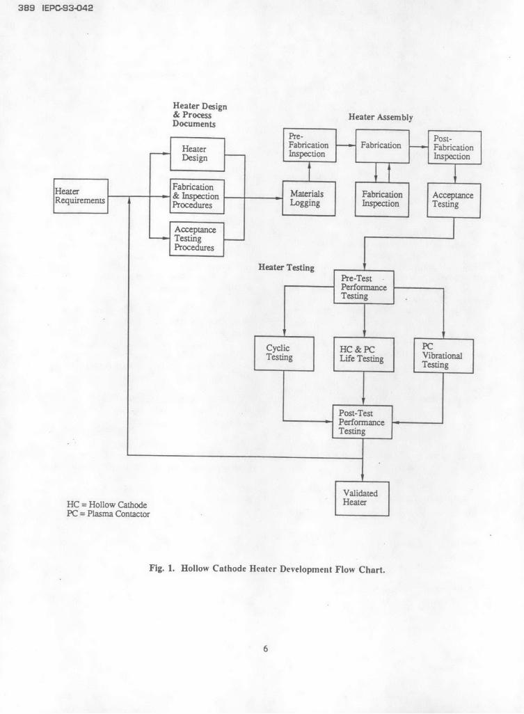
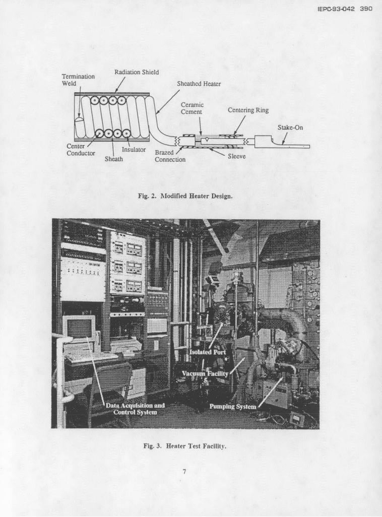
The heater design was sheathed concept and is All testing was conducted within a 0.31 m innershown in Fig. 2. The basic elements of the heater are diameter, 0.36 m long stainless steel port that wasthe center conductor, the insulator, the sheath, the mounted onto Vacuum Facility 5 at LeRC. The testterminations, and the radiation shield. The center facility is shown in Fig. 3. lTe port was isolatedconductor is the heat source, the sheath encloses the from Vacuum Facility 5 and was pumped by a turbo-heating element and closes the electrical circuit, and molecular pump that was backed by a mechanicalthe insulator provides electrical isolation for and pump. Base port pressures were on the order ofthermal conduction between the center conductor and 1.3x 10 Pa (lx l0 torr) as measured by an ionizationsheath. The terminations couple the center conductor gauge. A low background pressure was necessary to
2
IEPC-93-0 4 2 386
preclude excessive oxidation of heater and cathode increased to preclude the center conductor fromcomponents which could result in inaccurate perfor- making contact with the sheath during the swagingmance data and/or failure. Since past tests of process. The reduced swaging resulted in a largersheathed heaters were successfully conducted within center conductor diameter than the J-series cathodethis pressure range.'0 this range was adequate. heater. The heater impedance at ignition temperature
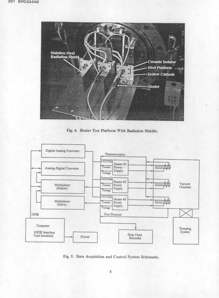
The heaters were mounted onto hollow cathodes was 1.1 0. Although this low impedance imposes awith electron emitting inserts installed to simulate the loss in power processor efficiency due to the lowcathode thermal mass. The cathodes were secured to operating voltages, heater reliability is increased dueceramic isolators that were mounted on a steel plat- to the decreased probability of damaging the centerform with stainless steel sheet metal for radiation conductor during the swaging process. For the heatershields, as shown in Fig. 4. This arrangement was termination, the center conductor of the sheatheddesigned to accommodate the testing of three heaters heater was welded to a larger diameter wire. Asimultaneously. No attempt was made to initiate a sleeve was brazed to the sheathed heater and filleddischarge. with a high temperature ceramic cement. This assem-
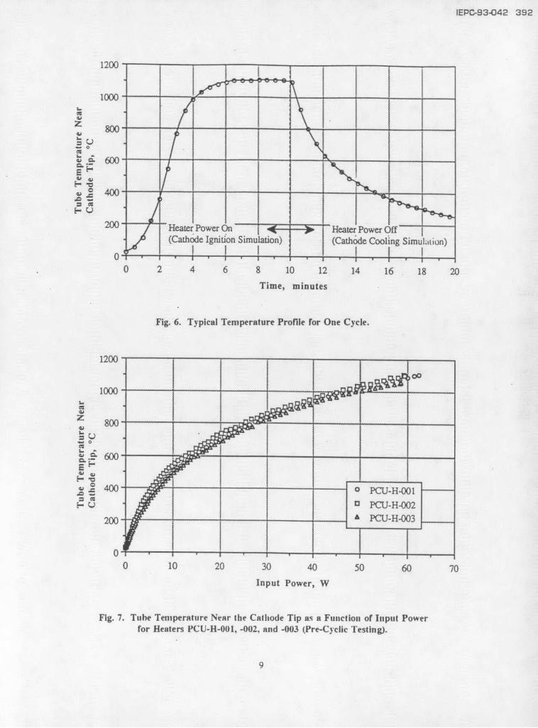
A schematic of the computerized data acquisition bly removes stress from the center conductor andand control (DAC) system utilized for heater testing reduces resistive power losses. The wire was termi-is shown in Fig. 5. A computer and a digital-to- nated with a stake-on. The radiation shield was aanalog converter were used with a General Purpose metal foil shield that was wrapped around the heaterInterface Bus (GPIB) to control three 16 V, 10 A DC coils and was retained by spot-welds.heater power supplies. Use of direct current for thehollow cathode heater allows for reduced conducted Heater Test Proceduresand radiated electromagnetic interference during Heater testing consisted of performance andplasma contactor activation and ignition. With the cyclic testing. Performance testing involved rampingheater as a load, the current regulation and ripple of the heater input current to a fixed current level inthe power supplies were < 0.8% and < 0.81%. respec- order to measure the tube temperature near thetively. The computer-GPIB configuration was further cathode tip as a function of input power. This testused to control two 16 channel multiplexers and an was conducted before and after cyclic testing. Theanalog-to-digital converter for data acquisition. The heater produced a maximum tube temperature of ~multiplexers, which contained signal conditioners to 1100* C. Cyclic testing involved cycling the heaterelectrically isolate the DAC system and to condition to ignition temperatures for 6000 cycles. Each cycleincoming signals, were commanded to send their consisted of 10 minutes at high heat input power toanalog signals to an analog-to-digital convener which simulate ignition and 10 minutes at power off forthen was commanded to send the converted digitized cooling. A typical temperature characteristic is shownsignals to the computer via the GPIB. The computer in Fig. 6. The ignition time simulation was a maxi-saved these data on an external disk drive and printed mum value chosen pending testing to determine ana hard copy. Monitored parameters included heater actual ignition time. The cooling time was chosen tocurrents and voltages, tube temperatures near the impose a significant thermal stress on the heater whilecathode tip, and port pressure. Currents were mea- minimizing cycle time. The rate of heater coolingsured with current transducers, voltages with volt was found to decrease substantially within the first 10meters, temperatures with platinun/platinum-13% minutes of heater power shut-down.rhodium thermocouples, and port pressures with anionization gauge. A strip rhart recorder was installed Results and Discussionto continuously monitor the heater currents, voltages,and the port pressure. To date, three heaters have been tested. The
first heater, labeled PCU-H-001. was cycled to failure.Heater Design The following two heaters, labeled PCU-HF-002 and
The modified heater design is shown in Fig. 2. PCU-H-003. have been performance tested and areIt is a modified version of the J-series ion thnrster currently under cyclic testing. The following sectionsheater design. It consists of a sheathed heater with 8 will present and discuss the test results of each heater.helical coils used to heat the hollow cathode. Theamount of swaging was reduced to avoid damaging Heater PCLI-H-001the center conductor and the insulation thickness was The first heater tested, labeled PCU-H-001, was
3
387 IEPC-93-042
assembled without any inspection of the hardware in the heater sheath-sleeve interface temperature wasduring fabrication. Furthermore, acceptance testing probably the result of the cooling effect caused by thewas not conducted. The testing objectives of this increased emissivity at this location. Finally, a visualheater were to verify that the heater termination examination of the ceramic cement revealed that itdesign was satisfactory and to obtain an initial esti- was very brittle. The brittleness was found to bemate on the cyclic lifetime capability of the design. caused, in part. by an improper mixing of the com-During the installation of the heater onto the hollow pound that resulted in a weakened ceramic.cathode, the heater sheath surface and shape weredamaged. However, since no heater insulation was Heaters PCU-H-002 & -003exposed and the heater cold resistance did not change, The following two heaters, labeled PCU-H-002testing was initiated. To ensure that the temperature and -003, were fabricated and inspected according toat the sheath/sleeve interface did not exceed the the process documents. The installation procedure ofbrazing temperature, a platinum/platinum-13% rhodi- the heater onto the cathode was modified to preventum thermocouple was spot-welded onto the sheath at damaging the test article. Acceptance testing wasthis interface to monitor the temperature. successfully conducted for both heaters. Pre-test cold
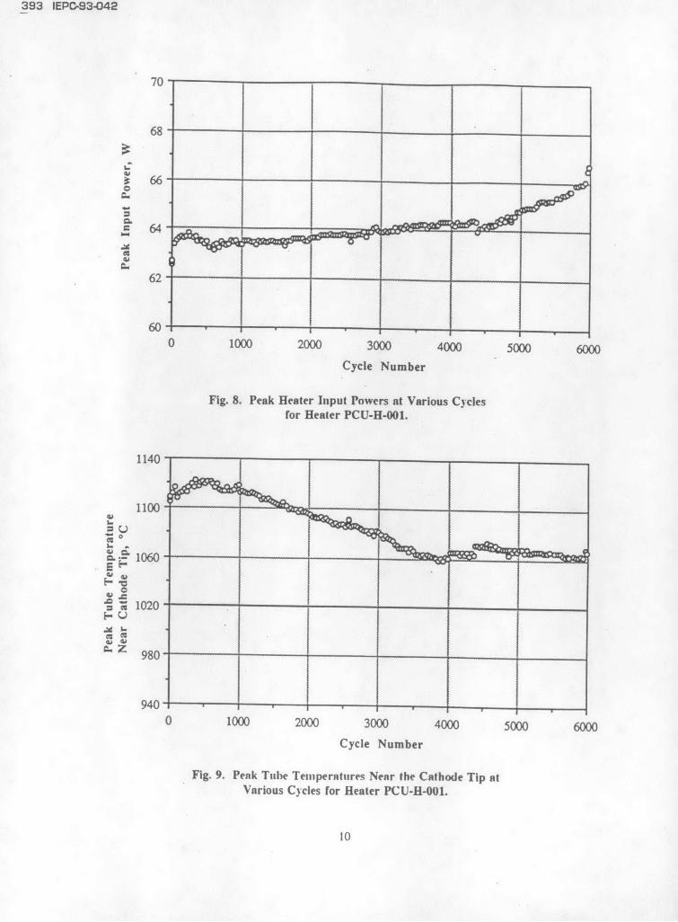
The performance of the heater before cyclic resistance measurements of the thermocouple attach-testing, as characterized by the tube temperature near ments to the cathode tubes were made in order tothe cathode tip as a function of input power, is shown monitor any changes in this junction. Cold resistancein Fig. 7. The heater termination design was found to measurements indicated that the fabrication of thesebe satisfactory, and so cyclic testing of the heater was heaters duplicated that of PCU-H-001.initiated. Peak heater input powers, cathode tube The performance of all heaters is compared intemperatures, and heater sheath/sleeve interface Fig. 7. At the ignition input current, tube temperaturetemperatures for various cycles are plotted in Fig. 8, near the cathode tip and input power repeatability9. and 10, respectively. The heater input power were within 44 °C and 3.5 W, respectively. Theincreased by 1.8% of the starting value within the disparity in the cathode tube temperatures were partlyfirst 233 cycles, indicating that a "bum-in" of the due the difficulty in maintaining an exact thermocou-heater had occurred. By cycle 4359, the input power pie location from heater to heater. As a result, thishad risen linearly by 3.0%. By cycle 5933, the input disparity was considered acceptable. The repeatabilitypower had risen by 5.6% at an increased linear rate. of input power was equivalent to that of past ionThe heater input power then increased sharply by thruster heater testing.' 0
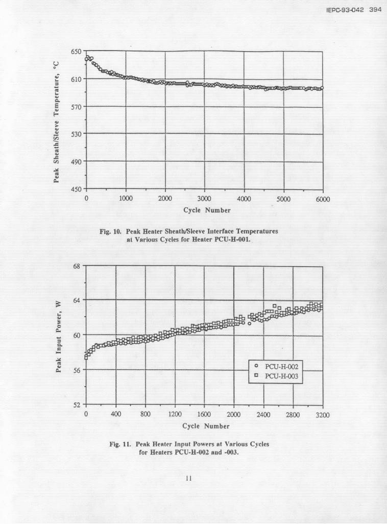
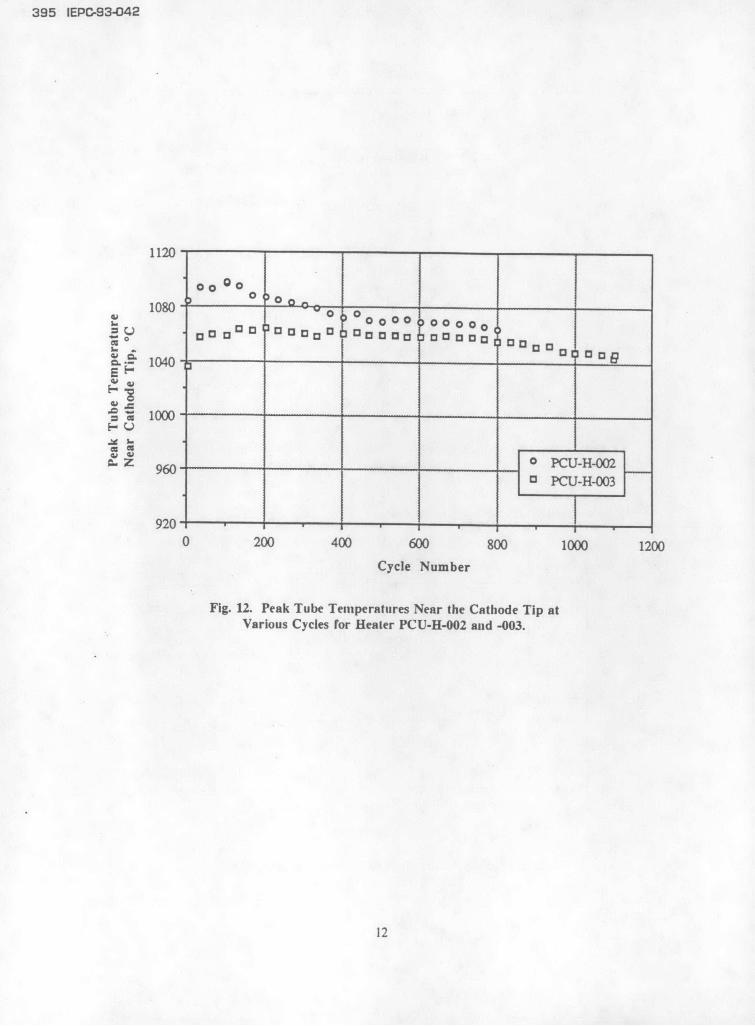
6.7% during cycle 5985, after which the heater failed. The heaters are currently being cycled and haveThe cathode tube temperature increased by 17 "C completed 3178 cycles to date. The peak inputwithin the first 577 cycles after which the temperature powers and cathode tube temperatures for variousdecreased by 63 "C by cycle 3859. The heater cycles are shown in Fig. 1 and 12, respectively. Thesheath-sleeve interface temperature also decreased by heater input powers of heaters PCU-H-002 and -00342 *C of the starting value by cycle 5933. increased by 2.1% and 2.8%, respectively, within the
The heater was inspected after failure to deter- first 300 cycles indicating that a "burn-in" of themine the cause of the failure and to identify any other heaters bad occurred, similar to that of heater PCU-H-problems. A radiographic examination of the heater 001. By cycle 3178, the heater input powers in-revealed nothing conclusive. A destructive examina- creased linearly by ~ 10% of the starting values, 4tion of the heater revealed a break in the center times greater than that of heater PCU-H-001. Theconductor at the fourth coil from the weld of the cause of this change is unknown. Power levelscenter conductor to the sheath. The cause of this between heaters PCU-H-002 and -003 differed by lessdiscontinuity is unknown, however it is anticipated than 1.8%. The cathode tube thermocouples forthat it is due, in part, to prior mishandling during heaters PCU-H-002 and -003 failed to operate proper-assembly. The cathode tube thermocouple immedi- ly after cycles 802 and 1104, respectively, for un-ately separated from the cathode tube upon removal known reasons. The cathode tube temperatures forof the heater from the vacuum facility. The decrease heaters PCU-H-002 and -003 increased by 13 *C andin the cathode tube temperature shown in Fig. 9 may 27 "C, respectively, within the first 135 cycles, andhave been due to a poor thermocouple attachment. A then started to decrease. This trend was also ob-visual examination of the heater sleeve revealed served with heater PCU-H-001. Temperature differ-discoloration resulting from oxidation. The decrease ences between heaters PCU-H-002 and -003 were as
4
IEPC-93-042 388
high as 48 *C at the beginning of the test. but were 'Rawlin. V. K. and Majcher. G. A.. "Massless than 9 *C by cycle 8U2. Comparisons of Electric Propulsion Systems for
NSSK of Geosynchronous Spacecraft," AIAA PaperConclusion 91-2347, June 1991.
A heater development program was established 'Beattie. J. R.. Matossian. J. N.. and Robson. R.to produce a reliable hollow cathode heater design for R., "Status of Xenon Ion Propulsion Technology."the Space Station plasma contactor. A heater design AIAA Paper 87-1003, May 1987.was determined and fabrication and inspection proce-dures were developed to ensure a repeatable design. 'Kitamura, S.. Miyazaki. K., and Hayakawa. Y..A heater test facility that utilized a computerized data "Cyclic Test of a 14 cm Diameter Ring-Cusp Xenonacquisition and control system was assembled. Heater Ion Thruster," AIAA Paper 92-3146, July 1992.testing was conducted to determine power require-ments for cathode activation and discharge ignition, 'Rohden. H. V.. et al.. "Endurance Test ofsingle unit operational repeatability, unit-to-unit PROEL Neutralizer for the RIT 10: Review of theoperational repeatability, and overall heater reliability. Activities at ESTEC Laboratories," IEPC Paper 91-Three heaters have been fabricated to date. The first, 026, October 1991.although damaged during assembly, completed 5985cycles before failing. The peak input power increased 'Kerslake, W. R. and Ignaczak. L. R.. "Devel-by 6.7% of the starting value and failed due to a opment and Flight History of SERT II Spacecraft,"break in the center conductor. Testing for two heaters Journal of Spacecraft and Rockets, Vol. 30, No. 3,is ongoing and 3178 cycles have been completed to May-June 1993, pp. 258-290.date. The heater-to-heater repeatability of tubetemperatures near the cathode tip and input powers at '"Mueller, L. A., "High Reliability Cathodethe ignition input current level were found to be Heaters for Ion Thrusters," AIAA Paper 76-1071.within 44 *C and 3.5 W, respectively. November 1976.
Additional heaters will be fabricated and tested.Results from cathode discharge and plasma contactor "Beattie, J. R. and Matossian, J. N.. "Mercurylife testing will be essential to determine if sputtering Ion Thruster Technology," NASA Contractor Reportof heater components will be a problem. Further- No. 174974, March 1989.more, heater design validation will require passingvibrational testing of the plasma contactor. 2Slutz, R. J., "A 10,000-hr Life Test of an
Engineering Model Resistojet," NASA TM-103216,References October 1990.
'Patterson, M. J., et al., "Plasma Contactor "Poeschel, R.L. and Dulgeroff, C. R., "RetrofitTechnology for Space Station Freedom," AIAA Paper and Verification Test of 30 cm Ion Thruster," NASA93-2228, June 1993. Contractor Report No. 165233. January 1980.
'Patterson. M. J. and Foster. J. E., "Performanceand Optimization of a "Derated" Ion Thruster forAuxiliary Propulsion," AIAA Paper 91-2350, June1991.
3Pollard. J. E., et al., "Electric Propulsion FlightExperience and Technology Readiness," AIAA Paper93-2221, June 1993.
4Schreib. R., "Readiness Appraisal: Ion Propul-sion for Communication Satellites," AIAA Paper 88-0777, May 1988.
5
389 IEPC-93-042
Heater Design& Process Heater AssemblyDocuments
Pre- Post-
Heater Fabrication Fabrication FabricationDesign Inspection Inspection
Requirements Procedures Logging Inspection Testing
Acceptance-Testing -Procedures
Heater TestingPre-TestPerformanceTesting
Cyclic HC &PCHowTesting Life Testing VibrationalTesting
PC = Plasma Contactor
Fig. 1. Hollow Cathode Heater Development Flow Chart.
6
IEPC-93-042 390
.Radiation ShieldTerminationWeld Sheathed Heater
CeramicCement Centering Ring
Stake-On
Center /Conductor Insulator Brazed /Sl
Sheath Connectionleeve
Fig. 2. Modified Heater Design.
Fig. 3. Heater Test Facility.
7
391 IEPC-93-042
Fig. 4. Heater Test Platform With Radiation Shields.
Digital-Analog Converter Theocouples
Commandr ----- Heater #1
Analog-Digital Converter cu nt Power. lS i- - Supply
Voluge
Command
Muliplxer Heater #2Multiplexer QCurn Power acuu r(Master) - Supply C ham
Multiplexer Current Power ... .....(Sl av e)
- - supply
GPIB Pon Pressure
Computer
(GPIB Interface SystemCard Installed) Printer SRecorder
Fig. 5. Data Acquisition and Control System Schematic.
8
IEPC-93-042 392
1200
1000-
S800--
1600
S 1000 _
. 600
., -- _ o PCU-H-001 ---_
.. o PCU-H400200
. 0 -
0 " y ~Heater Power On <-- > ~Heater Power OffS(Cathode Ignition Simulation) (Cathode Cooling SimuLkiion)
0 2 48 10 12 14 16 18 20
Time, minutes
Fig. 6. Typical Temperature Profile for One Cycle.
1200
1000-OR
S8300-____
.- 600
,w 4 00 0 PCU-H-001
13 PC U -H -002
200 - PCU-H-003
0 10 20 30 40 50 60 70
Input Power, W
Fig. 7. Tube Temperature Near the Calliode Tip as a Function of Input Powerfor Heaters PCU-H-001, -002, and -003 (Pre-Cyclic Testing).
9
393 IEPC-93-042
70
68
62
60
0 1000 2000 3000 4000 5000 6000
Cycle Number
Fig. 8. Peak Heater Input Powers at Various Cyclesfor Heater PCU-H-001.
1060 - -- ---------------
S1020-
z- 980S
940
0 1000 2000 3000 4000 5000 6000
Cycle Number
Fig. 9. Peak Tube Temperatures Near the Cathode Tip atVarious Cycles for Heater PCU-H-001.
10
IEPC-93-042 394
650 " --------650
S610
i-
E 570
490
450
.
0 1000 2000 3000 4000 5000 6000
U' 490 . --- ------ -----------
Cycle Number
Fig. 10. Peak Heater Sheath/Sleeve Interface Temperaturesat Various Cycles for Heater PCU-H-001.
68
64
60
0_____ ____ PCU-H-00206 56 .
a PCU-H-003
52 1....
0 400 800 1200 1600 2000 2400 2800 3200
Cycle Number
Fig. 11. Peak Heater Input Powers at Various Cyclesfor Heaters PCU-H-002 and -003.
11
395 IEPC-93-042
1120 1
1080 010 0 0 000 00~oo~ oa~o 0000,00000
1313 __ 13____ 13 33 3 1 1 1
0_ _ _ 09 0 U M 0 UH-0
r- 960 ---- J
920' * * ~ ..
0 200 400 600 800 1000 1200Cycle Number
Fig. 12. Peak Tube Temperatures Near the Cathode Tip atVarious Cycles for Heater PCU-H-002 anid -003.
12