cathode ray oscilloscope (cro) -...
TRANSCRIPT
CATHODE RAY OSCILLOSCOPE (CRO)
4.6 (a) Cathode rays
CORE
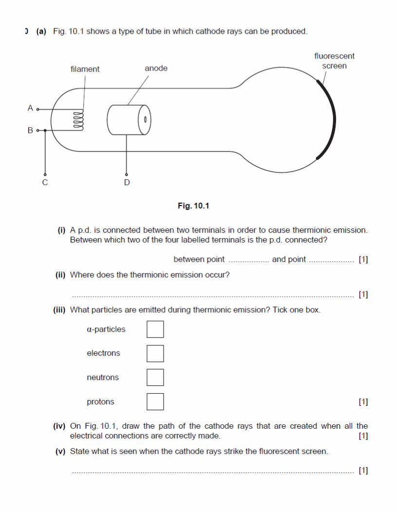
Describe the production and detection of cathode rays
Describe their deflection in electric fields
State that the particles emitted in thermionic emission are electrons
4.6 (b) Simple treatment of cathode–ray oscilloscopes
EXT.
Describe(in outline) the basic structure and action of the cathode-ray oscilloscope
(detailed circuits are not required)
Use and describe the use of a cathode-ray oscilloscope to display waveforms
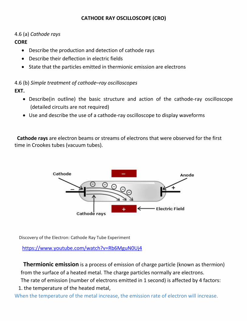
Cathode rays are electron beams or streams of electrons that were observed for the first time in Crookes tubes (vacuum tubes).
Discovery of the Electron: Cathode Ray Tube Experiment
https://www.youtube.com/watch?v=Rb6MguN0Uj4
Thermionic emission is a process of emission of charge particle (known as thermion)
from the surface of a heated metal. The charge particles normally are electrons.
The rate of emission (number of electrons emitted in 1 second) is affected by 4 factors:
1. the temperature of the heated metal,
When the temperature of the metal increase, the emission rate of electron will increase.
2. the surface area of the heated metal,
When the surface area of the metal increase, the emission rate of electron will increase.
3. the types of metal
The rates of thermionic emission are different with regard to different types of metals.
4. the coated material on the surface of the metal.
If the surface is coated by a layer of barium oxide or strontium oxide, the rate of emission will
become higher.
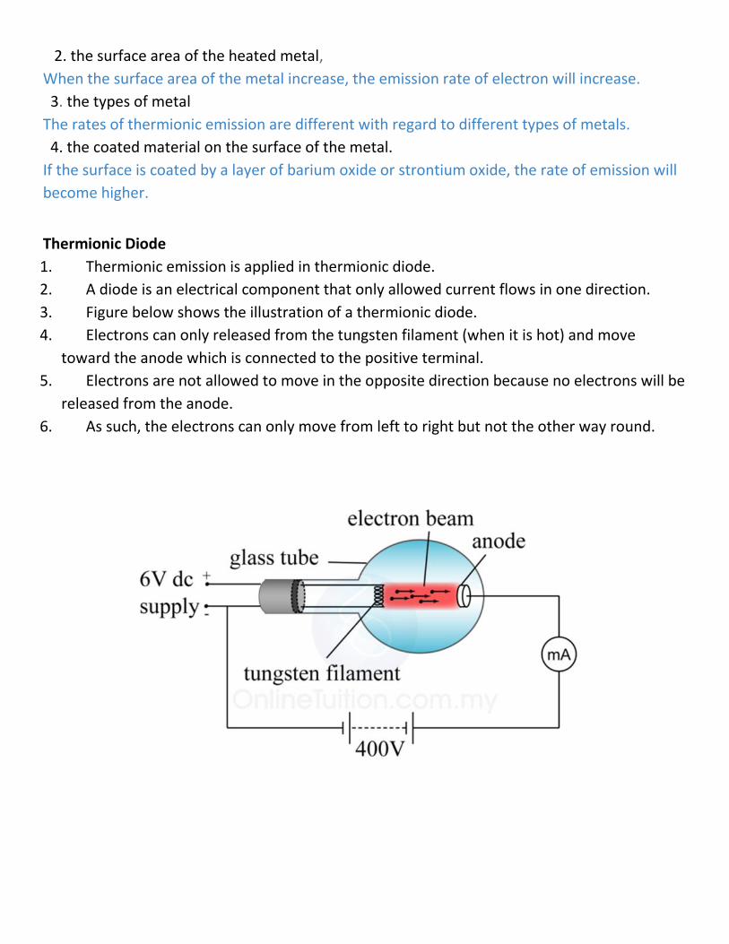
Thermionic Diode
1. Thermionic emission is applied in thermionic diode.
2. A diode is an electrical component that only allowed current flows in one direction.
3. Figure below shows the illustration of a thermionic diode.
4. Electrons can only released from the tungsten filament (when it is hot) and move
toward the anode which is connected to the positive terminal.
5. Electrons are not allowed to move in the opposite direction because no electrons will be
released from the anode.
6. As such, the electrons can only move from left to right but not the other way round.
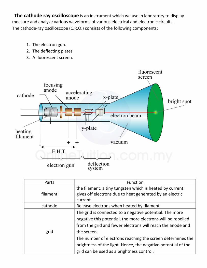
The cathode ray oscilloscope is an instrument which we use in laboratory to display
measure and analyze various waveforms of various electrical and electronic circuits.
The cathode-ray oscilloscope (C.R.O.) consists of the following components:
1. The electron gun.
2. The deflecting plates.
3. A fluorescent screen.
Parts Function
filament the filament, a tiny tungsten which is heated by current, gives off electrons due to heat generated by an electric current.
cathode Release electrons when heated by filament
grid
The grid is connected to a negative potential. The more
negative this potential, the more electrons will be repelled
from the grid and fewer electrons will reach the anode and
the screen.
The number of electrons reaching the screen determines the
brightness of the light. Hence, the negative potential of the
grid can be used as a brightness control.

Focusing anode and accelerating anode
The anode at positive potential accelerates the electrons
and the electrons are focused into a fine beam as they
pass through the anode.
Electron gun The electron gun makes a narrow beam of electrons. Its cathode gives off electrons and anode accelerate them.
y-plate The Y-plates will cause deflection in the vertical direction when a voltage is applied across them.
x-plate The X-plates will cause the electron beam to be deflected in the horizontal direction if a voltage is applied across them.
The fluorescent screen
1. The screen is coated with a fluorescent salt, for example, zinc sulphide.
2. When the electrons hit the screen, it will cause the salt to produce a flash of light and
hence a bright spot on the screen.
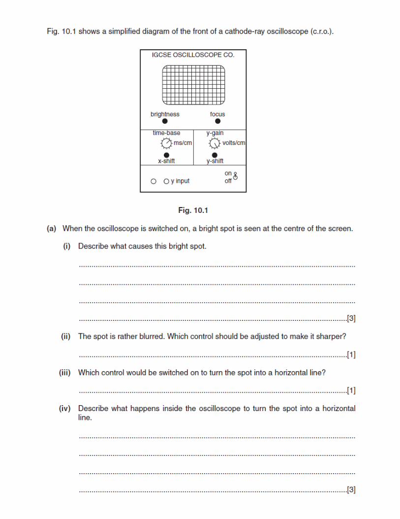
Using CRO
Function
1. Power switch To switch on and off of the oscilloscope
2. Focus control To control the focus of the spot on the screen.
3. Intensity control To control the brightness of the spot on the screen.
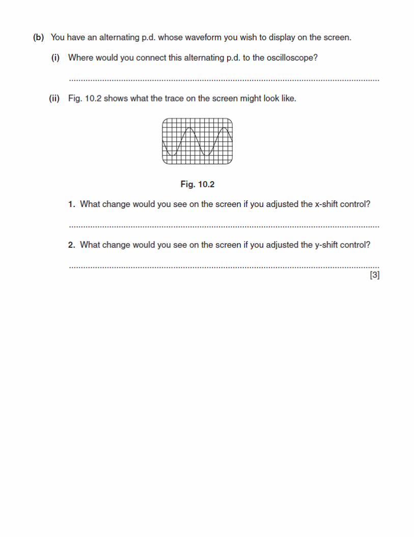
4. X-offset
5. Y-offset
Y-offset moves the whole trace vertically up and down on the
screen, while X-offset moves the whole trace from side to side on
the screen.
6. Time base
control
Whenever we switch on the time-base, we are actually applying a
sawtooth voltage to the X-plates (Figure below)
* This make the electron beam sweep across the screen at a
constant speed.
* By knowing the period of each cycle, T, we can then know how
fast the beam is sweeping across the screen. The time-base is thus
a measure of time for the oscilloscope.
7. Y gain control * the "Volts/Div." wheels amplify an input signal so that for a
division a given voltage level is in valid. A "division" is a segment, a
square on the screen of the oscilloscope.
* A setting of ".5" i.e. means, that the height of a single square
equals a voltage of 0.5 V. An amplitude of 1 V would have a size of
two divisions vertical to the abscissa.
8. d.c./a.c. switch d.c. – d.c. and a.c. voltage displayed.
a.c. – only a.c. voltage displayed.
9. X-input and Y-
input
Electric input connect to the X-plate and Y-plate.
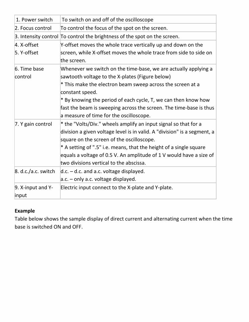
Example
Table below shows the sample display of direct current and alternating current when the time
base is switched ON and OFF.
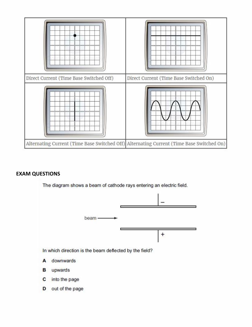
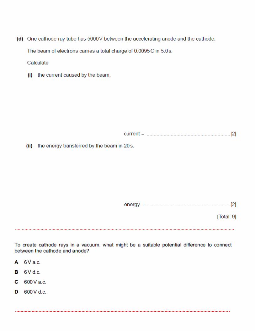
EXAM QUESTIONS

EXTENDED
……………………………………………………………………………………………………………………………………………….
………………………………………………………………………………………………………………………………………..

CORE S12