thermal characteristics of a lanthanum...
TRANSCRIPT
Thermal Characteristics of a Lanthanum Hexaboride
Hollow Cathode
IEPC-2015-44/ISTS-2015-b-44
Presented at Joint Conference of 30th International Symposium on Space Technology and Science,34th International Electric Propulsion Conference and 6th Nano-satellite Symposium
Hyogo-Kobe, JapanJuly 4–10, 2015
James E. Polk∗, Dan Goebel†, and Pablo Guerrero ‡
A lanthanum hexaboride hollow cathode is under development as one of two options forthe Hall Effect Rocket with Magnetic Shielding (HERMeS), a 12.5 kW thruster targetedat applications such as the proposed Asteroid Robotic Retrieval Mission (ARRM). A labo-ratory model version of this cathode was instrumented with thermocouples to characterizethe thermal behavior over currents ranging from 10 to 50 A and xenon flow rates of 8 to25 sccm. Ignition tests show that an insert temperature of 1340◦C or higher is requiredfor reliable discharge initiation. These temperatures can be achieved with a heater currentof 10 A, corresponding to a heater power of 230 W. The heater temperature at this powerlevel is over 1550◦C. Peak emitter temperatures during cathode operation ranged from1410 to 1650◦C, yielding conservative cathode lifetime predictions of greater than 100,000hours for the range of currents required for HERMeS. These data are being used to refinethermal models that will be employed in maturing the cathode design and in more detailedmodels of temperature-driven failure modes.
I. Introduction
NASA is developing high power electric propulsion systems for a range of robotic science and human ex-ploration missions, such as the proposed Asteroid Robotic Retrieval Mission (ARRM). ARRM is designedto demonstrate key power and propulsion system technologies by visiting a near-Earth asteroid, obtaininga multi-ton boulder from its surface, and placing it in a stable orbit around the moon.1,2 Follow-on mis-sions using the ARRM system could include robotic pre-deployment of heavy cargoes and piloted missions.3–6
These missions require extremely long propulsion system lifetimes, so a primary focus is on developing highlyreliable components and verifying their lifetime. For example, ARRM requires thruster operation for up to50,000 hours with 50% margin, so a total lifetime capability of 75,000 hours must validated.
To help retire technical risks for a high power solar electric propulsion technology demonstration missions suchas ARRM, the NASA Glenn Research Center and the Jet Propulsion Laboratory are jointly developing theHall Effect Rocket with Magnetic Shielding (HERMeS), a 12.5 kW thruster that employs several technologiesfor long life.7,8 The focus of the investigation we report here is on the thermal characteristics of a lanthanumhexaboride (LaB6) cathode under development as one option for the HERMeS thruster. The nominaloperating envelope for the HERMeS thruster is between 6.25 and 12.5 kW and voltages between 300 V and800 V (corresponding to specific impulses ranging from 1750 to 3000 s). This throttling range requires thatthe cathode produce discharge currents of 8.9 to 31.3 A. The nominal cathode flow rate is 7% of the totalmass flow rate.
Two candidate cathode technologies are under development for the HERMeS thruster–a dispenser cathode
∗Principal Engineer, Propulsion and Materials Engineering Section, Jet Propulsion Laboratory, California Institute of Tech-nology, M/S 125-109, 4800 Oak Grove Drive, Pasadena, CA 91109
†Senior Research Scientist, Propulsion and Materials Engineering Section, Jet Propulsion Laboratory, California Instituteof Technology, M/S 125-109, 4800 Oak Grove Drive, Pasadena, CA 91109
‡Graduate student, California Institute of Technology, 1200 E. California Blvd., Pasadena, CA 91125
1Joint Conference of 30th ISTS, 34th IEPC and 6th NSAT, Hyogo-Kobe, Japan
July 4–10, 2015
which employs a porous tungsten emitter impregnated with a barium calcium aluminate mixture and alanthanum hexaboride cathode. Both technologies appear to have long life capability and a rich heritage inflight applications,9 but each has unique advantages and disadvantages. Lanthanum hexaboride, for instance,is more resistant to poisoning by oxidizing impurities in the propellant, which may be a key advantage forsystems with very large propellant loads.9,10 ARRM, for example, may require as much as 10,000 kg ofxenon propellant. However, LaB6 operates at higher temperatures and requires a higher temperature heaterwhich may be subject to greater risk of wear-out failures. The current development program is designed tomap the cathode throttling range (the topic of a separate paper11), demonstrate sufficiently robust cathodeheaters, and validate the cathode lifetime.
As part of this development we have instrumented a laboratory model LaB6 cathode with thermocouples todetermine how the component temperatures vary with discharge current and voltage. The specific objectivesof the thermal testing include:
• Characterize cathode heater thermal behavior to optimize the design and guide development of heaterlifetime models.
• Determine heater power and insert temperature required for reliable cathode ignition.
• Characterize insert thermal behavior as an input to cathode plasma models and to assess cathode life.
• Obtain data to benchmark and validate cathode thermal models.
This paper describes the test article, the operating conditions, and the insert and heater temperaturesmeasured over a range of discharge currents and flow rates of interest for the HERMeS thruster applica-tion.
II. Experimental Characterization of Thermal Behavior
A. The Lanthanum Hexaboride Hollow Cathode
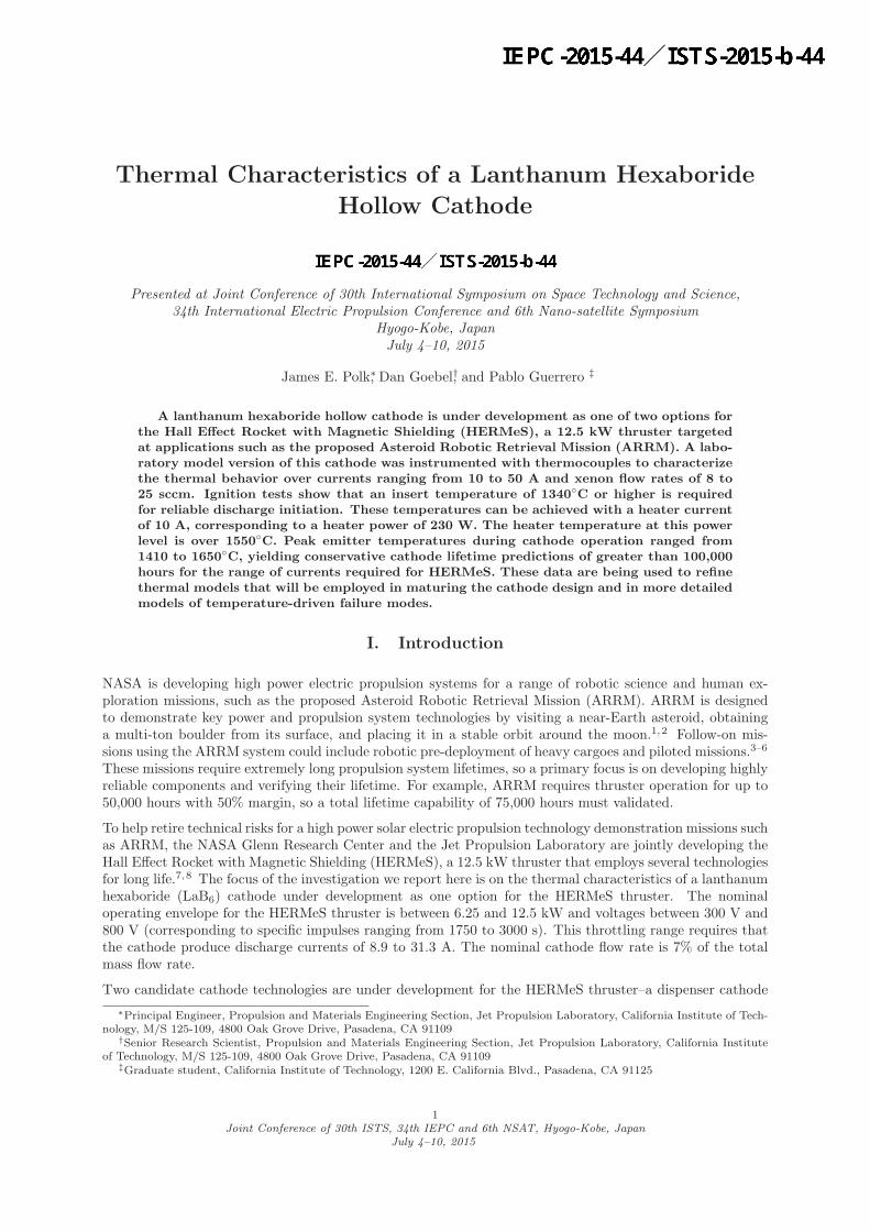
A laboratory model version of the lanthanum hexaboride hollow cathode under development for the HERMeSthruster is shown in Fig. 1 and described in more detail in a companion paper.11 The laboratory model
Figure 1. Second generation laboratory model lanthanum hexaboride hollow cathode.
version consists of a cylindrical lanthanum hexaboride insert in a molybdenum tube with a tungsten orificeplate at the downstream end. Very thin graphite sleeves around the insert prevent direct contact betweenit and the refractory metal components. A thin-walled graphite tube located inside the cathode tube andupstream of the insert is used to constrain it axially. A tungsten spring upstream of the graphite tubeprovides a pre-load that holds the insert against the orifice plate. A coaxial swaged heater wrapped around
2Joint Conference of 30th ISTS, 34th IEPC and 6th NSAT, Hyogo-Kobe, Japan
July 4–10, 2015
the cathode tube is used to preheat the cathode prior to ignition. After initiation of the discharge theplasma heat load is sufficient to maintain the required operating temperature and the heater is turned off.Ten wraps of tantalum foil are used as a radiation shield around the heater to minimize radiative heat losses.A graphite keeper encloses the cathode assembly and serves as a starter electrode during cathode ignition.The cathode and keeper electrodes are electrically isolated from each other with an insulator located betweentheir flanges. The cathode flange bolts to a plate through which the xenon propellant is fed. The assemblyis clamped together with grafoil gasket seals in the laboratory model cathode, but a design in which themechanical joints and seals are replaced with brazed joints is under development.
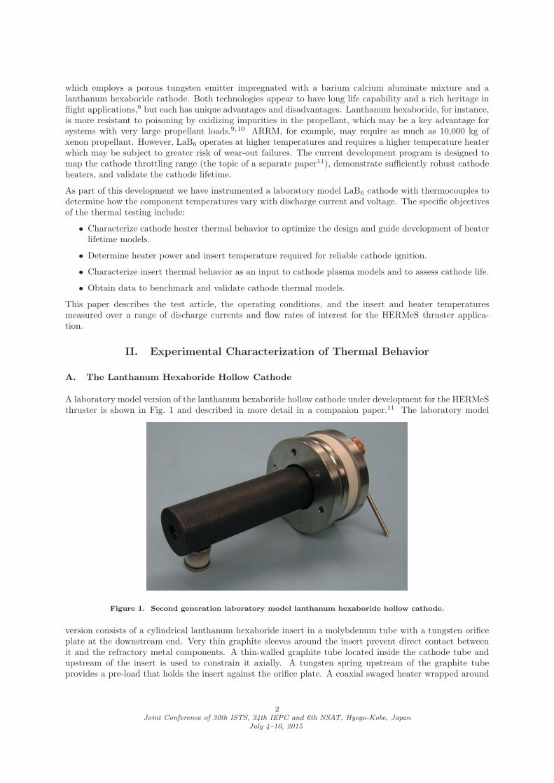
The laboratory model version of the cathode represents a second generation of the 1.5 cm diameter design.The temperature measurements were obtained using the first generation design, which is shown with thethermocouple instrumentation in Fig. 2. In this configuration the dimensions of the components in contact
Figure 2. First generation of the 1.5 cm diameter lanthanum hexaboride hollow cathode instrumented withthermocouples.
with the plasma are the same as the second generation laboratory model cathode, but there are minordifferences in some of the other components. The first generation design employs a graphite cathode tubewhich is 37% shorter than in the second generation design. The heater is a similar design and uses thesame materials, but has a sheath diameter of 2.4 mm instead of the more robust 3 mm diameter heater usedin the second generation cathode. The cathode attaches to a stainless steel flange which is mounted to aflanged stainless steel tube. This connects to a block into which the propellant feed line is manifolded. Thesedifferences will affect thermal conduction in the assembly so they are incorporated in the thermal model thatis under development.
B. Thermocouple Instrumentation
Thermocouple measurements have proven to be challenging in lanthanum hexaboride hollow cathodes be-cause of the high temperatures, chemical interactions between the thermocouple wire materials and graphiteand lanthanum hexaboride, and limited access to the interior. Type C tungsten-rhenium thermocouples ratedto 2320◦C were employed in the highest temperature regions and type K nickel-chromium/nickel-aluminumthermocouples rated to 1250◦C were used at the back of the assembly where temperatures were lower. Thelimits of error for the Type K and type C thermocouples are 0.75% and 1% of reading, respectively.
Measurements in the LaB6 insert and the graphite components required the use of sheathed thermocoupleassemblies to limit diffusion of carbon and boron into the tungsten-rhenium wires, which can cause rapidshifts in the thermocouple calibration. These assemblies consist of a thermocouple in hafnia insulation witha swaged tantalum sheath 1.6 mm in diameter. The thermocouple junction is located near the end of thesheath, which is welded shut. The repeatability of the measurements over the course of these tests indicatesthat the calibration was stable and unaffected by materials interactions.
3Joint Conference of 30th ISTS, 34th IEPC and 6th NSAT, Hyogo-Kobe, Japan
July 4–10, 2015
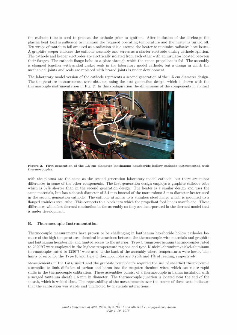
After many unsuccessful attempts to instrument the LaB6 insert, a configuration which yielded reliablemeasurements was developed. Three axial thermocouple wells with different depths were drilled in the wallof the emitter, as shown in Fig. 3. Sheathed thermocouple assemblies were routed through slots in the flange
Figure 3. Photo and schematic of axial thermocouple wells in the lanthanum hexaboride insert.
at the back of the cathode tube and inserted into the thermocouple wells from upstream. The depths ofthe wells were chosen to place the thermocouple junctions at three different axial positions–16.9, 10.8, and1.7 mm from the downstream end of the insert. The shortest thermocouple well at the upstream end of theinsert still has a length-to-diameter ratio of 4.
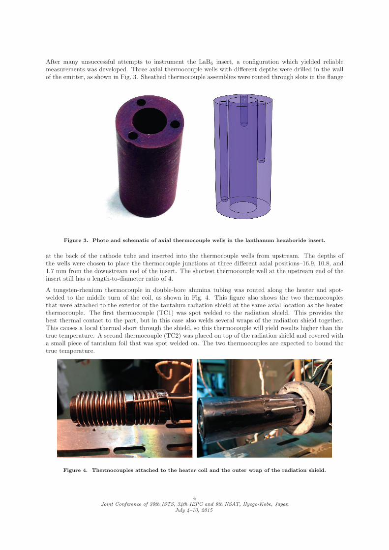
A tungsten-rhenium thermocouple in double-bore alumina tubing was routed along the heater and spot-welded to the middle turn of the coil, as shown in Fig. 4. This figure also shows the two thermocouplesthat were attached to the exterior of the tantalum radiation shield at the same axial location as the heaterthermocouple. The first thermocouple (TC1) was spot welded to the radiation shield. This provides thebest thermal contact to the part, but in this case also welds several wraps of the radiation shield together.This causes a local thermal short through the shield, so this thermocouple will yield results higher than thetrue temperature. A second thermocouple (TC2) was placed on top of the radiation shield and covered witha small piece of tantalum foil that was spot welded on. The two thermocouples are expected to bound thetrue temperature.
Figure 4. Thermocouples attached to the heater coil and the outer wrap of the radiation shield.
4Joint Conference of 30th ISTS, 34th IEPC and 6th NSAT, Hyogo-Kobe, Japan
July 4–10, 2015

Additional sheathed thermocouples are inserted in small holes in the cathode flange (type C), keeper flange(type K), and the alumina insulator between them (type C). The holes in the keeper flange and insulatorhave length-to-diameter ratios (L/D) of 2 to 2.5, and the cathode flange hole has an L/D of 5. TypeK thermocouples are spot welded to the flange to which the cathode tube attaches and the upstream anddownstream flanges of the mounting tube. These additional measurements are being used to help benchmarkthe cathode thermal model.
C. Test Facility
The cathode was operated in a 1 m diameter by 2 m long vacuum facility which was pumped by two 25cm diameter cryopumps. Pressure was monitored with a Granville Phillips Stabil Ion Gauge calibrated withxenon gas. The base pressure was typically 1 × 10⁻⁴ Pa (8 × 10⁻⁷ Torr) and the pressure during cathodeoperation ranged from 1.3− 4× 10⁻² Pa (1− 3× 10⁻⁴ Torr).
Ultra-high purity xenon (99.9995% pure) was used as the propellant. The flow rate was measured with athermal mass flow meter and the metering valve was mounted in the vacuum chamber so that all external feedlines were above atmospheric pressure to eliminate the possibility of air leaks into the flow system. All feedsystem tubing and components have electropolished wetted surfaces and metal seals. The volumetric flowrate was calibrated by measuring the rate of pressure rise in a known volume, yielding flow rate measurementswith an uncertainty of less than 2%. A computer data system was used for flow setpoint control and datalogging.
Heater and discharge power were provided by commercial power supplies with the common returns groundedto the vacuum tank. The cathode was also grounded to the chamber through the mounting structure.Currents and voltages were measured to within 1% by the data system using calibrated shunts and voltagedividers.
D. Operating Conditions
The cathode insert had been used previously, but was grit-blasted to produce a clean surface for theseexperiments. The cathode was then operated at a range of currents for a burn-in period of about 40 hoursbefore the discharge voltage and insert temperatures became repeatable at a given operating point.
The thermal characteristics of the cathode with heater power only (no discharge) were measured for heatercurrents of 3 to 10 A. The temperatures were allowed to reach steady state at each fixed current level. Thecathode was operated at discharge current levels of 10 to 50 A and flow rates ranging from 8 to 25 sccm tocharacterize the thermal behavior with a plasma discharge. At a given current level it was initially run at aflow rate of 13 sccm and the discharge voltage, keeper floating voltage, and all temperatures were allowed toreach steady state. This could take up to 4 or 5 hours after first starting the cathode or after throttling upor down in current. These transient times are much longer than time scales expected for thermal diffusion,and are likely due in part to changes in the insert surface chemistry.
After stable data at 13 sccm were obtained, the flow rate was varied. In this case the voltages and the insert,heater, and radiation shield temperatures were allowed to reach steady state. The other temperatures onthe cathode assembly were typically within a few degrees of steady state, based on extrapolations fromexponential curve fits.
Finally, a series of ignition tests were performed to determine the heater setpoint and insert temperaturesrequired to reliably start the cathode. The temperatures were allowed to stabilize for a given heater currentbetween 8 and 10.25 A. Then the flow rate was set to 13 sccm and the discharge power supply was enabledwith a setpoint of 20 A. If the discharge did not ignite, the keeper power supply was enabled with asetpoint of 0.5 A. The keeper and discharge power supply voltage and current transients were captured onan oscilloscope.
5Joint Conference of 30th ISTS, 34th IEPC and 6th NSAT, Hyogo-Kobe, Japan
July 4–10, 2015
E. Results
1. Heater Thermal Behavior
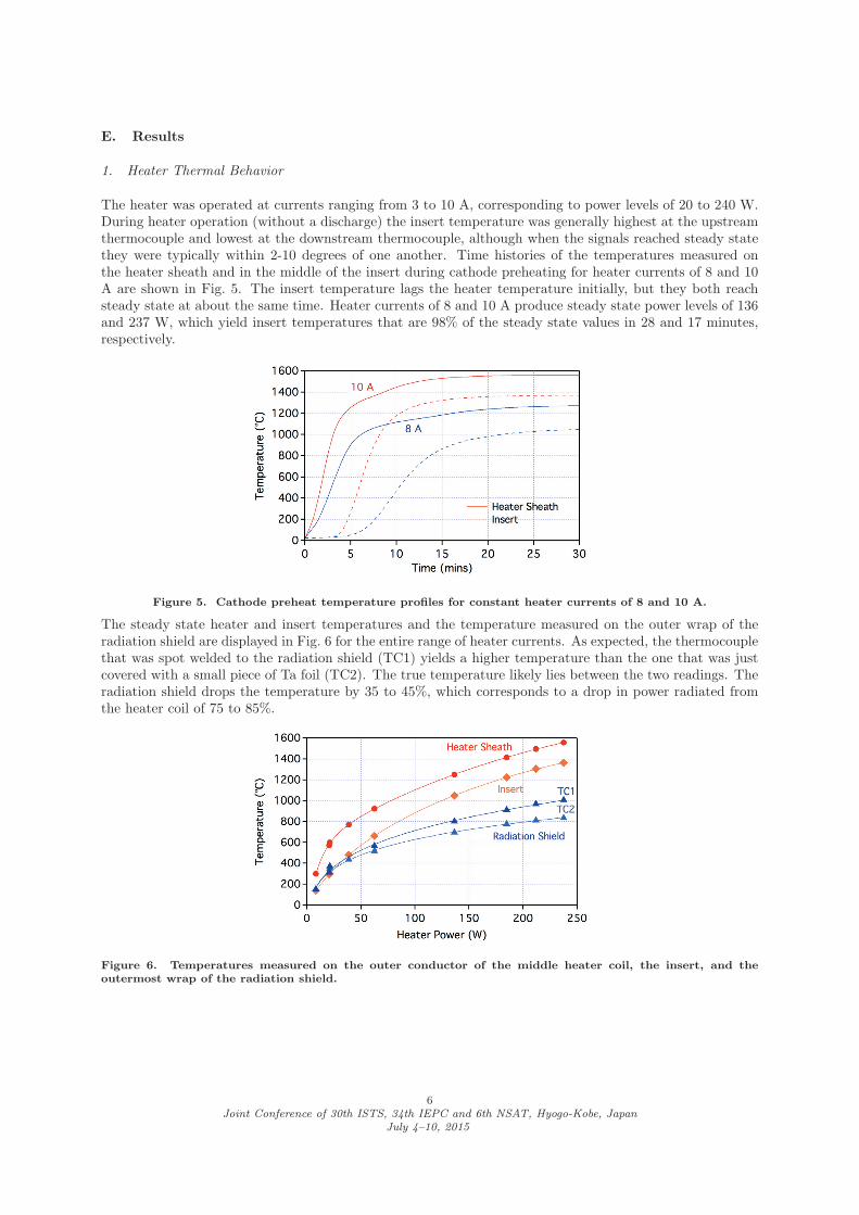
The heater was operated at currents ranging from 3 to 10 A, corresponding to power levels of 20 to 240 W.During heater operation (without a discharge) the insert temperature was generally highest at the upstreamthermocouple and lowest at the downstream thermocouple, although when the signals reached steady statethey were typically within 2-10 degrees of one another. Time histories of the temperatures measured onthe heater sheath and in the middle of the insert during cathode preheating for heater currents of 8 and 10A are shown in Fig. 5. The insert temperature lags the heater temperature initially, but they both reachsteady state at about the same time. Heater currents of 8 and 10 A produce steady state power levels of 136and 237 W, which yield insert temperatures that are 98% of the steady state values in 28 and 17 minutes,respectively.
Figure 5. Cathode preheat temperature profiles for constant heater currents of 8 and 10 A.
The steady state heater and insert temperatures and the temperature measured on the outer wrap of theradiation shield are displayed in Fig. 6 for the entire range of heater currents. As expected, the thermocouplethat was spot welded to the radiation shield (TC1) yields a higher temperature than the one that was justcovered with a small piece of Ta foil (TC2). The true temperature likely lies between the two readings. Theradiation shield drops the temperature by 35 to 45%, which corresponds to a drop in power radiated fromthe heater coil of 75 to 85%.
Figure 6. Temperatures measured on the outer conductor of the middle heater coil, the insert, and theoutermost wrap of the radiation shield.
6Joint Conference of 30th ISTS, 34th IEPC and 6th NSAT, Hyogo-Kobe, Japan
July 4–10, 2015

Figure 7. Range of current levels and temperatures over which the cathode was successfully ignited and themeasured delay between initiation of the keeper discharge and start of the main discharge.
2. Cathode Ignition
Figure 7 shows the heater and insert temperatures measured prior to cathode ignition and the delay betweeninitiation of the 0.5 A keeper discharge and the 20 A main discharge for heater currents ranging from 8 to10.25 A. The cathode successfully started over this entire range at a flow rate of 13 sccm with application ofkeeper voltage, but at 8 A heater current there was evidence of arcing and at heater currents less than about9.75 A there was a significant delay between the ignition of a keeper discharge and the start of the maindischarge. This indicates that the insert was not hot enough to supply the full discharge current initially andrequired additional preheating by the keeper discharge. The delay and the peak keeper voltage at ignitiondecreased monotonically with increasing heater current. Above 9.75 A the delay went to zero and the keepervoltage was ≤ 40 V. At 10 A the cathode often started on the 50 V open circuit voltage of the dischargepower supply alone.
These data indicate that reliable ignitions for this geometry require insert temperatures over about 1340◦Cand voltages on the keeper over 40 V. These temperatures can be achieved in this cathode with heatercurrents and powers of 10 A and 230 W or greater.
3. Current-Voltage Characteristics
The discharge voltage and floating voltage of the keeper electrode are shown in Fig. 8 for currents rangingfrom 10 to 50 A at a flow rate of 13 sccm. The discharge voltage trend is similar to that measured on the
Figure 8. Discharge voltage and keeper floating voltage as a function of discharge current at a flow rate of 13sccm.
7Joint Conference of 30th ISTS, 34th IEPC and 6th NSAT, Hyogo-Kobe, Japan
July 4–10, 2015
laboratory model cathode,11 but the values are about 5 V higher. In these tests the discharge voltage variedsignificantly during the 40 hour burn-in period. The keeper voltages were stable, however, and agree wellwith those from the laboratory model cathode. These results suggest that the higher voltages were an anodephenomenon which should not affect internal cathode temperatures. Discharge voltage trends as a functionof current for the other flow rates were similar, with higher voltages at lower flow rates for a given current.The keeper voltage increased slightly with flow rate at a given current.
4. Steady-state Operating Temperatures
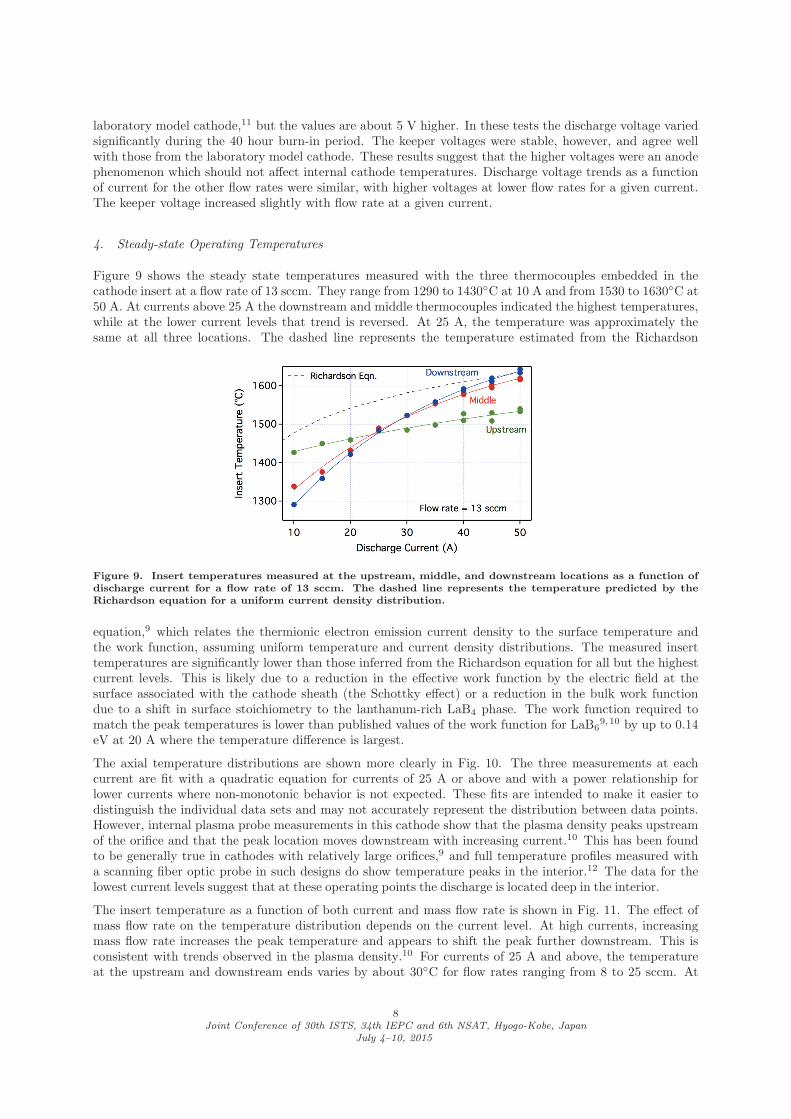
Figure 9 shows the steady state temperatures measured with the three thermocouples embedded in thecathode insert at a flow rate of 13 sccm. They range from 1290 to 1430◦C at 10 A and from 1530 to 1630◦C at50 A. At currents above 25 A the downstream and middle thermocouples indicated the highest temperatures,while at the lower current levels that trend is reversed. At 25 A, the temperature was approximately thesame at all three locations. The dashed line represents the temperature estimated from the Richardson
Figure 9. Insert temperatures measured at the upstream, middle, and downstream locations as a function ofdischarge current for a flow rate of 13 sccm. The dashed line represents the temperature predicted by theRichardson equation for a uniform current density distribution.
equation,9 which relates the thermionic electron emission current density to the surface temperature andthe work function, assuming uniform temperature and current density distributions. The measured inserttemperatures are significantly lower than those inferred from the Richardson equation for all but the highestcurrent levels. This is likely due to a reduction in the effective work function by the electric field at thesurface associated with the cathode sheath (the Schottky effect) or a reduction in the bulk work functiondue to a shift in surface stoichiometry to the lanthanum-rich LaB4 phase. The work function required tomatch the peak temperatures is lower than published values of the work function for LaB6
9,10 by up to 0.14eV at 20 A where the temperature difference is largest.
The axial temperature distributions are shown more clearly in Fig. 10. The three measurements at eachcurrent are fit with a quadratic equation for currents of 25 A or above and with a power relationship forlower currents where non-monotonic behavior is not expected. These fits are intended to make it easier todistinguish the individual data sets and may not accurately represent the distribution between data points.However, internal plasma probe measurements in this cathode show that the plasma density peaks upstreamof the orifice and that the peak location moves downstream with increasing current.10 This has been foundto be generally true in cathodes with relatively large orifices,9 and full temperature profiles measured witha scanning fiber optic probe in such designs do show temperature peaks in the interior.12 The data for thelowest current levels suggest that at these operating points the discharge is located deep in the interior.
The insert temperature as a function of both current and mass flow rate is shown in Fig. 11. The effect ofmass flow rate on the temperature distribution depends on the current level. At high currents, increasingmass flow rate increases the peak temperature and appears to shift the peak further downstream. This isconsistent with trends observed in the plasma density.10 For currents of 25 A and above, the temperatureat the upstream and downstream ends varies by about 30◦C for flow rates ranging from 8 to 25 sccm. At
8Joint Conference of 30th ISTS, 34th IEPC and 6th NSAT, Hyogo-Kobe, Japan
July 4–10, 2015
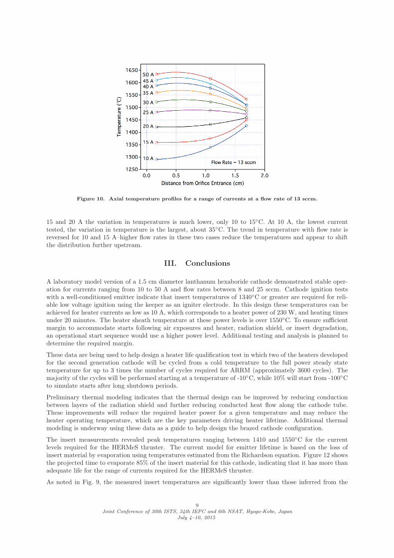
Figure 10. Axial temperature profiles for a range of currents at a flow rate of 13 sccm.
15 and 20 A the variation in temperatures is much lower, only 10 to 15◦C. At 10 A, the lowest currenttested, the variation in temperature is the largest, about 35◦C. The trend in temperature with flow rate isreversed for 10 and 15 A–higher flow rates in these two cases reduce the temperatures and appear to shiftthe distribution further upstream.
III. Conclusions
A laboratory model version of a 1.5 cm diameter lanthanum hexaboride cathode demonstrated stable oper-ation for currents ranging from 10 to 50 A and flow rates between 8 and 25 sccm. Cathode ignition testswith a well-conditioned emitter indicate that insert temperatures of 1340◦C or greater are required for reli-able low voltage ignition using the keeper as an igniter electrode. In this design these temperatures can beachieved for heater currents as low as 10 A, which corresponds to a heater power of 230 W, and heating timesunder 20 minutes. The heater sheath temperature at these power levels is over 1550◦C. To ensure sufficientmargin to accommodate starts following air exposures and heater, radiation shield, or insert degradation,an operational start sequence would use a higher power level. Additional testing and analysis is planned todetermine the required margin.
These data are being used to help design a heater life qualification test in which two of the heaters developedfor the second generation cathode will be cycled from a cold temperature to the full power steady statetemperature for up to 3 times the number of cycles required for ARRM (approximately 3600 cycles). Themajority of the cycles will be performed starting at a temperature of -10◦C, while 10% will start from -100◦Cto simulate starts after long shutdown periods.
Preliminary thermal modeling indicates that the thermal design can be improved by reducing conductionbetween layers of the radiation shield and further reducing conducted heat flow along the cathode tube.These improvements will reduce the required heater power for a given temperature and may reduce theheater operating temperature, which are the key parameters driving heater lifetime. Additional thermalmodeling is underway using these data as a guide to help design the brazed cathode configuration.
The insert measurements revealed peak temperatures ranging between 1410 and 1550◦C for the currentlevels required for the HERMeS thruster. The current model for emitter lifetime is based on the loss ofinsert material by evaporation using temperatures estimated from the Richardson equation. Figure 12 showsthe projected time to evaporate 85% of the insert material for this cathode, indicating that it has more thanadequate life for the range of currents required for the HERMeS thruster.
As noted in Fig. 9, the measured insert temperatures are significantly lower than those inferred from the
9Joint Conference of 30th ISTS, 34th IEPC and 6th NSAT, Hyogo-Kobe, Japan
July 4–10, 2015
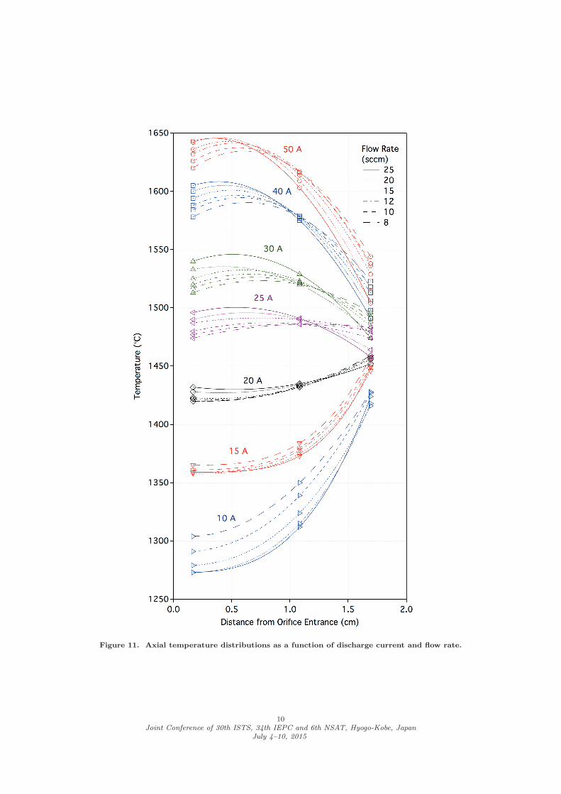
Figure 11. Axial temperature distributions as a function of discharge current and flow rate.
10Joint Conference of 30th ISTS, 34th IEPC and 6th NSAT, Hyogo-Kobe, Japan
July 4–10, 2015
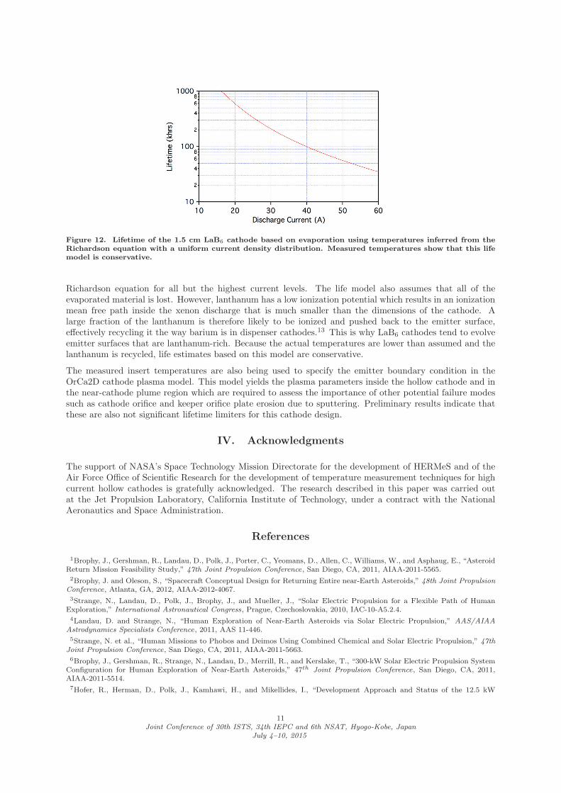
Figure 12. Lifetime of the 1.5 cm LaB6 cathode based on evaporation using temperatures inferred from theRichardson equation with a uniform current density distribution. Measured temperatures show that this lifemodel is conservative.
Richardson equation for all but the highest current levels. The life model also assumes that all of theevaporated material is lost. However, lanthanum has a low ionization potential which results in an ionizationmean free path inside the xenon discharge that is much smaller than the dimensions of the cathode. Alarge fraction of the lanthanum is therefore likely to be ionized and pushed back to the emitter surface,effectively recycling it the way barium is in dispenser cathodes.13 This is why LaB6 cathodes tend to evolveemitter surfaces that are lanthanum-rich. Because the actual temperatures are lower than assumed and thelanthanum is recycled, life estimates based on this model are conservative.
The measured insert temperatures are also being used to specify the emitter boundary condition in theOrCa2D cathode plasma model. This model yields the plasma parameters inside the hollow cathode and inthe near-cathode plume region which are required to assess the importance of other potential failure modessuch as cathode orifice and keeper orifice plate erosion due to sputtering. Preliminary results indicate thatthese are also not significant lifetime limiters for this cathode design.
IV. Acknowledgments
The support of NASA’s Space Technology Mission Directorate for the development of HERMeS and of theAir Force Office of Scientific Research for the development of temperature measurement techniques for highcurrent hollow cathodes is gratefully acknowledged. The research described in this paper was carried outat the Jet Propulsion Laboratory, California Institute of Technology, under a contract with the NationalAeronautics and Space Administration.
References
1Brophy, J., Gershman, R., Landau, D., Polk, J., Porter, C., Yeomans, D., Allen, C., Williams, W., and Asphaug, E., “AsteroidReturn Mission Feasibility Study,” 47th Joint Propulsion Conference, San Diego, CA, 2011, AIAA-2011-5565.2Brophy, J. and Oleson, S., “Spacecraft Conceptual Design for Returning Entire near-Earth Asteroids,” 48th Joint Propulsion
Conference, Atlanta, GA, 2012, AIAA-2012-4067.3Strange, N., Landau, D., Polk, J., Brophy, J., and Mueller, J., “Solar Electric Propulsion for a Flexible Path of Human
Exploration,” International Astronautical Congress, Prague, Czechoslovakia, 2010, IAC-10-A5.2.4.4Landau, D. and Strange, N., “Human Exploration of Near-Earth Asteroids via Solar Electric Propulsion,” AAS/AIAA
Astrodynamics Specialists Conference, 2011, AAS 11-446.5Strange, N. et al., “Human Missions to Phobos and Deimos Using Combined Chemical and Solar Electric Propulsion,” 47th
Joint Propulsion Conference, San Diego, CA, 2011, AIAA-2011-5663.6Brophy, J., Gershman, R., Strange, N., Landau, D., Merrill, R., and Kerslake, T., “300-kW Solar Electric Propulsion System
Configuration for Human Exploration of Near-Earth Asteroids,” 47th Joint Propulsion Conference, San Diego, CA, 2011,AIAA-2011-5514.7Hofer, R., Herman, D., Polk, J., Kamhawi, H., and Mikellides, I., “Development Approach and Status of the 12.5 kW
11Joint Conference of 30th ISTS, 34th IEPC and 6th NSAT, Hyogo-Kobe, Japan
July 4–10, 2015

HERMeS Hall Thruster for the Solar Electric Propulsion Technology Demonstration Mission ,” 34th International ElectricPropulsion Conference, Hyogo-Kobe, Japan, 2015, IEPC 2015-186.8Kamhawi, H., Haag, T., Huang, W., Herman, D., Thomas, R., Shastry, R., Yim, J., Chang, L., Clayman, L., Verhey, T.,
Griffith, C., Myers, J., Williams, G., Mikellides, I., Hofer, R., Polk, J., and Jorns, B., “Performance Characterization of theSolar Electric Propulsion Technology Demonstration Mission 12.5-kW Hall Thruster,” 34th International Electric PropulsionConference, Hyogo-Kobe, Japan, 2015, IEPC 2015-007.9Goebel, D. and Katz, I., Fundamentals of Electric Propulsion: Ion and Hall Thrusters, JPL Space Science and Technology
Series, 2008.10Chu, E. and Goebel, D., “High-Current Lanthanum Hexaboride Hollow Cathode for 10-to-50 kW Hall Thrusters,” IEEETrans. Plasma Sci., Vol. 40, No. 9, 2012, pp. 2133–2144.11Goebel, D. and Polk, J., “Lanthanum Hexaboride Hollow Cathode for the Asteroid Redirect Robotic Mission 12.5 kW HallThruster,” 34th International Electric Propulsion Conference, Hyogo-Kobe, Japan, 2015, IEPC 2015-XXX.12Polk, J., Goebel, D., and Tighe, W., “XIPS 25-cm Thruster Cathode Life Qualification for Use on Deep Space Missions ,”30th International Electric Propulsion Conference, Florence, Italy, 2007, IEPC 2007-193.13Polk, J., Mikellides, I., Katz, I., and Capece, A., “Tungsten and barium transport in the internal plasma of hollow cathodes,”J. Appl. Phys., Vol. 105, 2009, pp. 113301.
12Joint Conference of 30th ISTS, 34th IEPC and 6th NSAT, Hyogo-Kobe, Japan
July 4–10, 2015