lanthanum hexaboride hollow cathode for the...
TRANSCRIPT
1
Lanthanum Hexaboride Hollow Cathode for the Asteroid
Redirect Robotic Mission 12.5 kW Hall Thruster
By Dan M. Goebel and James E. Polk
Jet Propulsion Laboratory, California Institute of Technology, Pasadena, CA, USA (Received June 21st, 2015)
A lanthanum hexaboride hollow cathode has been developed for use in the 12.5-kW Hall thruster under development for the proposed Asteroid Redirect Robotic Mission (ARRM). This cathode is larger than the original version developed at JPL that has operated successfully for years in the H6 Hall thruster, and has calculated lifetimes of 100 kh at 40 A of discharge current and over 50 kh at 50 A of discharge current. A 1.5-cm-dia. laboratory prototype of this cathode has been designed and built for testing with the Hall thruster under development for ARRM. This cathode has been successfully operated in our test facilities over the full operating gas flow rate and discharge current required for the ARRM mission concept.
Key Words: Hollow cathode, Lanthanum hexaboride, Hall thruster
1. Introduction The need for high-current, long-life cathodes for high power electric thrusters has spurred the development in the U.S. of lanthanum hexaboride (LaB6) hollow cathodes for space applications. LaB6 cathodes designed for space applications1 have demonstrated discharge current capabilities from 5 to 300 A, and have successfully operated in flight Hall thrusters for years2. As important from a spacecraft applications point of view is the extreme robustness of this cathode material against poisoning from propellant impurities or air exposures during testing. In addition, lanthanum hexaboride hollow cathodes have calculated lifetimes that exceed a hundred thousand hours at discharge currents of interest for the next generation solar electric propulsion missions.
Two different sizes of LaB6 hollow cathodes are being investigated for the HERMeS (Hall Effect Rocket with Magnetic Shielding) Hall thruster3. HERMeS is being developed for the Space Technology Mission Directorate (STMD) Solar Electric Propulsion Technology Demonstration Mission (SEP TDM) project. A mission concept for the SEP TDM is the proposed Asteroid Redirect Robotic Mission (ARRM)4,5. The HERMes Hall thruster is magnetically shielded6,7 to provide sufficient life and throughput for the nominal 50 kh thruster-on-time of this proposed mission. A prototype of this thruster has been designed and built8-10 and has been successfully tested at 12.5 kW at voltages between 400 and 800 V. This places a requirement on the cathode to produce 15.7 to 31.3 A of discharge current for the full thrusting on-time plus 50% margin, which is 75 kh.
The 0.8-cm-dia. LaB6 hollow cathode11 developed for the H6 Hall thruster12 runs at 5 to 60 A of discharge current, and the calculated life ranges from 75 kh at the minimum current of the HERMeS thruster to 10 kh at the maximum current. The 1.5-cm dia. LaB6 version of this cathode13,14 runs
nominally at 7.5 to 100 A of discharge, and the calculated life (discussed below) exceeds 100 kh over the full range of discharge currents needed for the ARRM mission.
A laboratory prototype version of the 1.5-cm-dia. LaB6 cathode has been built for testing and for operation in the HERMeS thruster. The 0.8-cm H6 cathode11 has been used in the H6 Hall thruster for 7 years to date and achieved over 1000 starts without failure. A 2-cm-dia. version this cathode demonstrated up to 300 A of discharge current and has been used in the 100-kW nested Hall thruster at the University of Michigan15. The newest version of the 1.5-cm-dia. LaB6 cathode features a more robust sheathed heater design presently undergoing flight qualification at JPL. This larger cathode, which is the main topic of this paper, has been fully tested and characterized over the desired discharge current range for the HERMeS thruster of 7.5 to 31.5 A, and the results and life predictions are discussed. 2. LaB6 Characteristics
Lanthanum hexaboride as an electron emitted in hollow has been fully described in previous publications1,2,11,13,14. Lanthanum hexaboride used in hollow cathodes is made by press-sintering LaB6 powder into rods and then machining the solid material to the desired shape to insert into the hollow cathode tube. The resultant insert material is polycrystalline and has a work function of about 2.67 eV depending on the surface stoichiometry. As shown in Fig. 1, this material will emit over 20 A/cm2 at a temperature of about 1700 ˚C, and since the bulk material is emitting there is no chemistry involved in maintaining the surface work function. Therefore, lanthanum hexaboride cathodes are relatively insensitive to impurities and air exposures that would normally destroy other cathodes. The LaB6 cathode life is determined primarily by the evaporation rate of the bulk LaB6 material at typical operating temperatures2.

2
Figure 2. Percentage of possible thermionic emission versus partial pressure of oxygen and water showing the poisoning of dispenser cathodes relative to LaB6.
The cathodes used in all Russian SPT Hall thrusters16,17 flown since the 1970’s use LaB6 electron emitters. Lanthanum hexaboride was also first used in the U.S. in a hollow cathode18 in the 1970’s. The lanthanum-boron material consists of combinations of stable LaB4, LaB6, and LaB9 compounds, with the surface color determined by the dominant compound. Lanthanum-boride compounds, heated to in excess of 1000 ˚C in vacuum congruently evaporate their components at a rate that produces a stable LaB6.0 surface. The evolution of LaB4 to LaB9 compounds is caused either by preferential sputtering of the boron or lanthanum atoms at the near surface by energetic ion bombardment, or by preferential chemical reactions with surface atoms. The low ion bombardment energy at the internal thermionic emitter surface characteristic of hollow cathodes, and the use of proper interface materials eliminates these effects. Lanthanum hexaboride must also be supported by materials that inhibit diffusion of boron into the support material, which embrittles most of the contacting refractory metals that can be used at the operating temperatures of LaB6. The crystalline LaB6 is also susceptible to breakage from mechanical stress and thermal shock. For these reasons, fine-grain graphite is used as the interface material due to it’s similar coefficient of thermal expansion as LaB6 and good electrical contact without significant boron diffusion or boride formation.
Lanthanum hexaboride cathodes can have long lifetimes because the evaporation rate is significantly lower than that of refractory metals and dispenser at thermionic emission temperatures. In spite of operating at a higher temperature, the LaB6 insert has a lower evaporation rate1 than the impregnate material in dispenser cathodes until the emission current exceeds about 15 A/cm2. References in the literature also describe the poisoning of LaB6 cathodes19. As shown in Fig. 2, at 1570˚C LaB6 cathodes can withstand oxygen partial pressures up to 10-4 Torr without degradation in the electron emission. For the case of xenon thrusters, LaB6 cathodes can tolerate the crudest grade of xenon commercially available (≈99.99% purity) without affecting the electron emission or
life. In addition, LaB6 cathodes do not require any significant conditioning, activation or purging procedures that are normally required by dispenser cathodes. These characteristics make the handling and processing of electric thrusters that use LaB6 cathodes relatively simple. 3. Cathode Configuration
The LaB6 hollow cathode configuration is similar to conventional space dispenser hollow cathodes2, which basically consists of a thermionic insert placed inside a structural cathode tube surrounded by a heater, heat shields, and keeper electrode. LaB6 cathodes of this design have been fabricated with insert outside diameters of 0.63-cm to 2-cm and cathode lengths from the exit orifice to the base flange from 6 cm to 15 cm for applications in various ion and Hall thrusters that require various cathode sizes1. The small LaB6 hollow cathode used in the H6 thruster was previously described in detail11 and has operated at discharge currents of 5 to 60 A. Likewise, the 1.5-cm-dia. cathode that is the subject of this paper was designed for operation from 10 to 100 A and a prototype was tested14 at discharge currents of up to 200 A.
Because LaB6 tends to chemically react with most materials when hot, the cathode tube can be made from non-reacting graphite or, for flight applications that require more robust structural characteristics, it can be fabricated from a refractory metal such as molybdenum. In this case, graphite sleeves are used to interface with and provide electrical contact the LaB6 insert. The keeper electrode used to start the discharge and protect the cathode orifice plate from back-ion bombardment from the cathode plume is also fabricated from graphite.
A schematic representation of the molybdenum-tube configuration for the 1.5-cm-dia. LaB6 hollow cathode is shown in Fig. 3. The LaB6 emitter is configured as a cylindrical insert and is slid inside the hollow molybdenum tube inside thin, close-fitting graphite sleeves. The insert is
Figure 1. Emission current density versus temperature.

3
Fig. 4. The 1.5-cm dia. LaB6 hollow cathode with 3-mm dia. heater installed (top) and heat shield installed without the keeper (bottom).
held in place by a thin carbon “pusher” tube and a tungsten spring placed inside the molybdenum tube as shown in Fig. 4 (top). The molybdenum tube is sufficiently long and thin to minimize conduction of heat from the insert to the base plate. The insert in this cathode has an inside diameter of 0.63 cm and a length of 5 cm, which provides 20 cm2 of emission area exposed to the plasma inside the hollow cathode. If the emission is uniform along the length of the insert, at an insert temperature of 1700 ˚C this cathode can emit 20 A/cm2 and therefore can produce total discharge current of 200 A. Recent experiments at JPL have shown that the LaB6 emitter temperature varies by only about 5% over it’s length at discharge currents up to 100 A, consistent with the more uniform plasma observed in these large, lower pressure cathodes compared to NSTAR2. This uniform insert temperature is used in the calculation of the evaporation-determined insert life. 4. Cathode heating and startup
Since the LaB6 cathode operates at several hundred degrees higher temperature than BaO-W dispenser cathodes, the heating and starting mechanisms are important. Conventional BaO-W dispenser cathodes typically use a coiled tantalum sheathed heater20,21 with magnesium-oxide powder insulation. This insulation material has a maximum operation temperature about 1400 ˚C, at which chemical reactions between the oxide insulation and the heater electrode or sheath material cause a reduction in the resistance and ultimately lead to failure of the heater21.
A coaxial sheathed-heater that incorporates high-temperature alumina-power insulation was developed and purchased from Idaho Labs to heat the cathode. The 0.24-cm-dia. Al2O3-insulated tantalum sheathed heater used in the H6 LaB6 cathode routinely provides 120 W of heater power for the 0.63-cm-dia. LaB6 cathode11, and has accumulated over 1000 starts to date. This same sheathed heater design with a 3-mm outer diameter is used for the 1.5-cm-dia. LaB6 cathode, and has a 50% longer length before winding than used in the smaller cathode in order to provide up to 300 W of heater power. The heater wound on the cathode tube is longer than the insert length, as seen in Fig. 4 (top), in order to heat and ignite the larger cathode.
The relatively thin molybdenum cathode tube reduces the heat conduction along the tube to the base to minimize the heater power requirements. Since these heaters as susceptible to grain growth and void formation if overheated, cycle life-testing and time-at-temperature testing of the alumina-insulated heaters have been started at JPL to investigate the failure mechanism and qualify this heater for space applications.
Also of importance is proper heat shielding of the cathode heater, which requires multiple wraps of thermal insulation outside the heater coils to minimize the radiated power and total amount of power required to start the cathode. The heater is wrapped with approximately ten turns of tantalum foil to act as a heat shield, and then enclosed by the graphite keeper. Figure 4 (bottom) shows the heat shielding installed in this cathode. The heat shield can be tied with Ta wire (as shown), or spot-welded in place.
Dispenser cathode discharges start by vacuum thermionic emission from the front of the cathode orifice plate32 due to barium that has diffused out of the orifice and activated the surface. This process requires time for the diffusion and surface chemistry to activate the surface and initiate emission. At a sufficient emission current, the ionization of the gas in the cathode to keeper gap provides plasma that flows into the orifice, couples into the insert region, and starts the plasma discharge. The LaB6 cathode, in comparison, does not have a
Fig. 3. Schematic drawing of the 1.5-cm-dia. LaB6 hollow cathode.
4
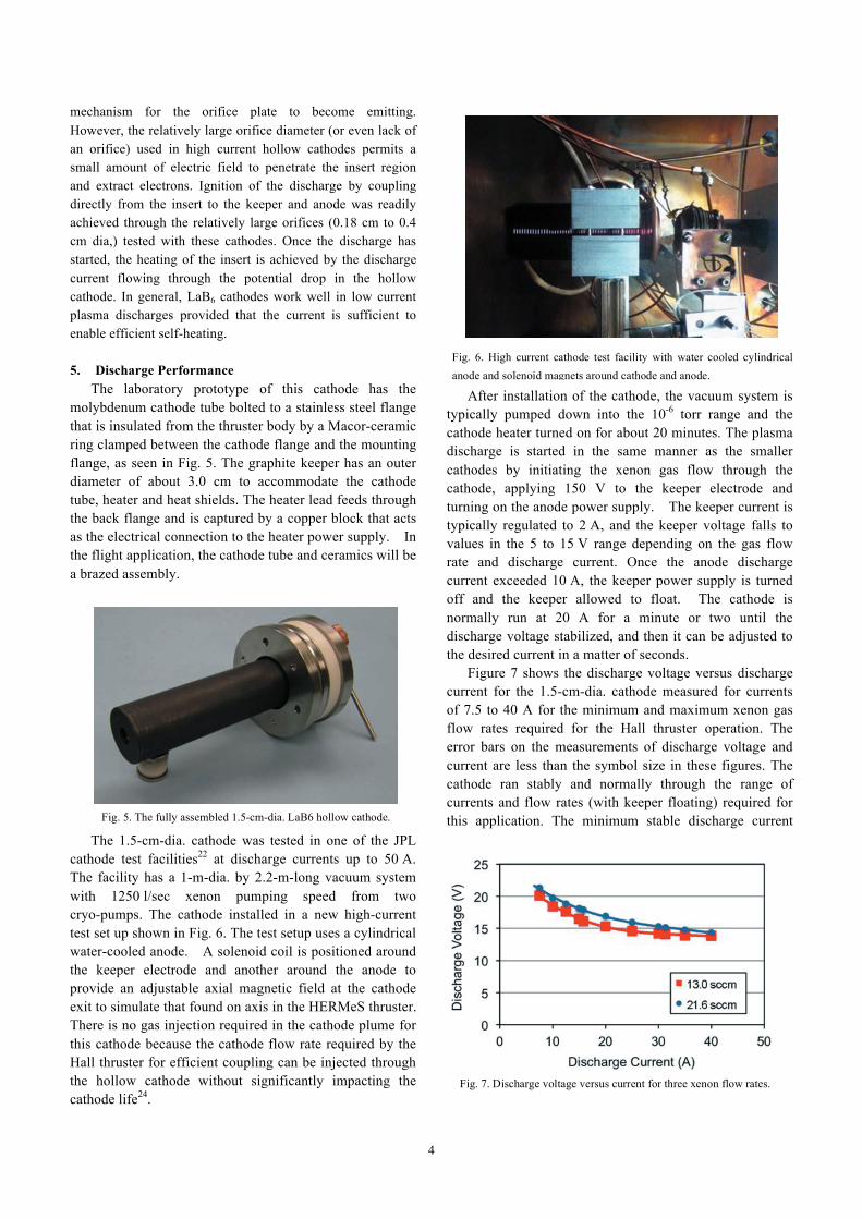
Fig. 5. The fully assembled 1.5-cm-dia. LaB6 hollow cathode.
mechanism for the orifice plate to become emitting. However, the relatively large orifice diameter (or even lack of an orifice) used in high current hollow cathodes permits a small amount of electric field to penetrate the insert region and extract electrons. Ignition of the discharge by coupling directly from the insert to the keeper and anode was readily achieved through the relatively large orifices (0.18 cm to 0.4 cm dia,) tested with these cathodes. Once the discharge has started, the heating of the insert is achieved by the discharge current flowing through the potential drop in the hollow cathode. In general, LaB6 cathodes work well in low current plasma discharges provided that the current is sufficient to enable efficient self-heating. 5. Discharge Performance
The laboratory prototype of this cathode has the molybdenum cathode tube bolted to a stainless steel flange that is insulated from the thruster body by a Macor-ceramic ring clamped between the cathode flange and the mounting flange, as seen in Fig. 5. The graphite keeper has an outer diameter of about 3.0 cm to accommodate the cathode tube, heater and heat shields. The heater lead feeds through the back flange and is captured by a copper block that acts as the electrical connection to the heater power supply. In the flight application, the cathode tube and ceramics will be a brazed assembly.
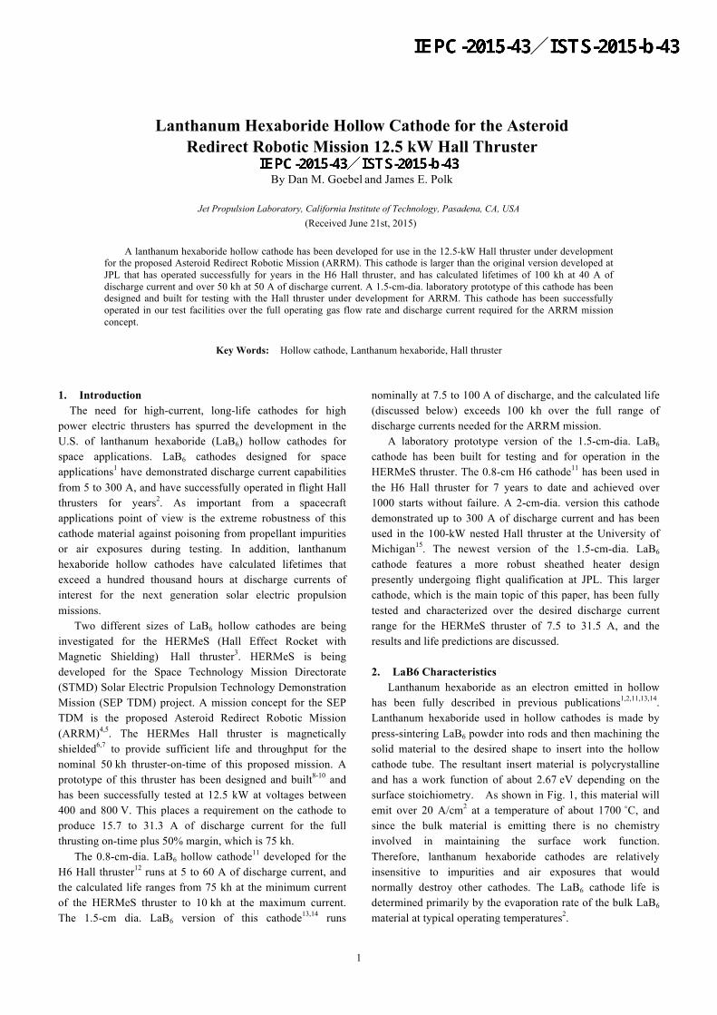
The 1.5-cm-dia. cathode was tested in one of the JPL cathode test facilities22 at discharge currents up to 50 A. The facility has a 1-m-dia. by 2.2-m-long vacuum system with 1250 l/sec xenon pumping speed from two cryo-pumps. The cathode installed in a new high-current test set up shown in Fig. 6. The test setup uses a cylindrical water-cooled anode. A solenoid coil is positioned around the keeper electrode and another around the anode to provide an adjustable axial magnetic field at the cathode exit to simulate that found on axis in the HERMeS thruster. There is no gas injection required in the cathode plume for this cathode because the cathode flow rate required by the Hall thruster for efficient coupling can be injected through the hollow cathode without significantly impacting the cathode life24.
After installation of the cathode, the vacuum system is typically pumped down into the 10-6 torr range and the cathode heater turned on for about 20 minutes. The plasma discharge is started in the same manner as the smaller cathodes by initiating the xenon gas flow through the cathode, applying 150 V to the keeper electrode and turning on the anode power supply. The keeper current is typically regulated to 2 A, and the keeper voltage falls to values in the 5 to 15 V range depending on the gas flow rate and discharge current. Once the anode discharge current exceeded 10 A, the keeper power supply is turned off and the keeper allowed to float. The cathode is normally run at 20 A for a minute or two until the discharge voltage stabilized, and then it can be adjusted to the desired current in a matter of seconds.
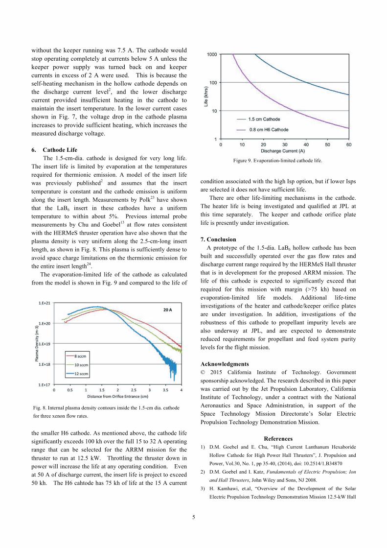
Figure 7 shows the discharge voltage versus discharge current for the 1.5-cm-dia. cathode measured for currents of 7.5 to 40 A for the minimum and maximum xenon gas flow rates required for the Hall thruster operation. The error bars on the measurements of discharge voltage and current are less than the symbol size in these figures. The cathode ran stably and normally through the range of currents and flow rates (with keeper floating) required for this application. The minimum stable discharge current
Fig. 6. High current cathode test facility with water cooled cylindrical anode and solenoid magnets around cathode and anode.
Fig. 7. Discharge voltage versus current for three xenon flow rates.
5
without the keeper running was 7.5 A. The cathode would stop operating completely at currents below 5 A unless the keeper power supply was turned back on and keeper currents in excess of 2 A were used. This is because the self-heating mechanism in the hollow cathode depends on the discharge current level2, and the lower discharge current provided insufficient heating in the cathode to maintain the insert temperature. In the lower current cases shown in Fig. 7, the voltage drop in the cathode plasma increases to provide sufficient heating, which increases the measured discharge voltage. 6. Cathode Life
The 1.5-cm-dia. cathode is designed for very long life. The insert life is limited by evaporation at the temperatures required for thermionic emission. A model of the insert life was previously published2 and assumes that the insert temperature is constant and the cathode emission is uniform along the insert length. Measurements by Polk23 have shown that the LaB6 insert in these cathodes have a uniform temperature to within about 5%. Previous internal probe measurements by Chu and Goebel13 at flow rates consistent with the HERMeS thruster operation have also shown that the plasma density is very uniform along the 2.5-cm-long insert length, as shown in Fig. 8. This plasma is sufficiently dense to avoid space charge limitations on the thermionic emission for the entire insert length24.
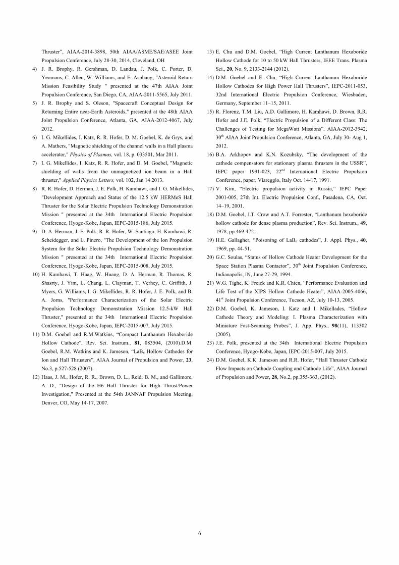
The evaporation-limited life of the cathode as calculated from the model is shown in Fig. 9 and compared to the life of
the smaller H6 cathode. As mentioned above, the cathode life significantly exceeds 100 kh over the full 15 to 32 A operating range that can be selected for the ARRM mission for the thruster to run at 12.5 kW. Throttling the thruster down in power will increase the life at any operating condition. Even at 50 A of discharge current, the insert life is project to exceed 50 kh. The H6 cahtode has 75 kh of life at the 15 A current
condition associated with the high Isp option, but if lower Isps are selected it does not have sufficient life.
There are other life-limiting mechanisms in the cathode. The heater life is being investigated and qualified at JPL at this time separately. The keeper and cathode orifice plate life is presently under investigation. 7. Conclusion A prototype of the 1.5-dia. LaB6 hollow cathode has been built and successfully operated over the gas flow rates and discharge current range required by the HERMeS Hall thruster that is in development for the proposed ARRM mission. The life of this cathode is expected to significantly exceed that required for this mission with margin (>75 kh) based on evaporation-limited life models. Additional life-time investigations of the heater and cathode/keeper orifice plates are under investigation. In addition, investigations of the robustness of this cathode to propellant impurity levels are also underway at JPL, and are expected to demonstrate reduced requirements for propellant and feed system purity levels for the flight mission. Acknowledgments © 2015 California Institute of Technology. Government sponsorship acknowledged. The research described in this paper was carried out by the Jet Propulsion Laboratory, California Institute of Technology, under a contract with the National Aeronautics and Space Administration, in support of the Space Technology Mission Directorate’s Solar Electric Propulsion Technology Demonstration Mission.
References 1) D.M. Goebel and E. Chu, “High Current Lanthanum Hexaboride
Hollow Cathode for High Power Hall Thrusters”, J. Propulsion and Power, Vol.30, No. 1, pp 35-40, (2014), doi: 10.2514/1.B34870
2) D.M. Goebel and I. Katz, Fundamentals of Electric Propulsion; Ion and Hall Thrusters, John Wiley and Sons, NJ 2008.
3) H. Kamhawi, et.al, “Overview of the Development of the Solar Electric Propulsion Technology Demonstration Mission 12.5-kW Hall
Fig. 8. Internal plasma density contours inside the 1.5-cm dia. cathode for three xenon flow rates.
Figure 9. Evaporation-limited cathode life.
6
Thruster”, AIAA-2014-3898, 50th AIAA/ASME/SAE/ASEE Joint Propulsion Conference, July 28-30, 2014, Cleveland, OH
4) J. R. Brophy, R. Gershman, D. Landau, J. Polk, C. Porter, D. Yeomans, C. Allen, W. Williams, and E. Asphaug, "Asteroid Return Mission Feasibility Study " presented at the 47th AIAA Joint Propulsion Conference, San Diego, CA, AIAA-2011-5565, July 2011.
5) J. R. Brophy and S. Oleson, "Spacecraft Conceptual Design for Returning Entire near-Earth Asteroids," presented at the 48th AIAA Joint Propulsion Conference, Atlanta, GA, AIAA-2012-4067, July 2012.
6) I. G. Mikellides, I. Katz, R. R. Hofer, D. M. Goebel, K. de Grys, and A. Mathers, "Magnetic shielding of the channel walls in a Hall plasma accelerator," Physics of Plasmas, vol. 18, p. 033501, Mar 2011.
7) I. G. Mikellides, I. Katz, R. R. Hofer, and D. M. Goebel, "Magnetic shielding of walls from the unmagnetized ion beam in a Hall thruster," Applied Physics Letters, vol. 102, Jan 14 2013.
8) R. R. Hofer, D. Herman, J. E. Polk, H. Kamhawi, and I. G. Mikellides, "Development Approach and Status of the 12.5 kW HERMeS Hall Thruster for the Solar Electric Propulsion Technology Demonstration Mission " presented at the 34th International Electric Propulsion Conference, Hyogo-Kobe, Japan, IEPC-2015-186, July 2015.
9) D. A. Herman, J. E. Polk, R. R. Hofer, W. Santiago, H. Kamhawi, R. Scheidegger, and L. Pinero, "The Development of the Ion Propulsion System for the Solar Electric Propulsion Technology Demonstration Mission " presented at the 34th International Electric Propulsion Conference, Hyogo-Kobe, Japan, IEPC-2015-008, July 2015.
10) H. Kamhawi, T. Haag, W. Huang, D. A. Herman, R. Thomas, R. Shasrty, J. Yim, L. Chang, L. Clayman, T. Verhey, C. Griffith, J. Myers, G. Williams, I. G. Mikellides, R. R. Hofer, J. E. Polk, and B. A. Jorns, "Performance Characterization of the Solar Electric Propulsion Technology Demonstration Mission 12.5-kW Hall Thruster," presented at the 34th International Electric Propulsion Conference, Hyogo-Kobe, Japan, IEPC-2015-007, July 2015.
11) D.M. Goebel and R.M.Watkins, “Compact Lanthanum Hexaboride Hollow Cathode”, Rev. Sci. Instrum., 81, 083504, (2010).D.M. Goebel, R.M. Watkins and K. Jameson, “LaB6 Hollow Cathodes for Ion and Hall Thrusters”, AIAA Journal of Propulsion and Power, 23, No.3, p.527-528 (2007).
12) Haas, J. M., Hofer, R. R., Brown, D. L., Reid, B. M., and Gallimore, A. D., "Design of the H6 Hall Thruster for High Thrust/Power Investigation," Presented at the 54th JANNAF Propulsion Meeting, Denver, CO, May 14-17, 2007.
13) E. Chu and D.M. Goebel, “High Current Lanthanum Hexaboride Hollow Cathode for 10 to 50 kW Hall Thrusters, IEEE Trans. Plasma Sci., 20, No. 9, 2133-2144 (2012).
14) D.M. Goebel and E. Chu, “High Current Lanthanum Hexaboride Hollow Cathodes for High Power Hall Thrusters”, IEPC-2011-053, 32nd International Electric Propulsion Conference, Wiesbaden, Germany, September 11–15, 2011.
15) R. Florenz, T.M. Liu, A.D. Gallimore, H. Kamhawi, D. Brown, R.R. Hofer and J.E. Polk, “Electric Propulsion of a Different Class: The Challenges of Testing for MegaWatt Missions”, AIAA-2012-3942, 30th AIAA Joint Propulsion Conference, Atlanta, GA, July 30- Aug 1, 2012.
16) B.A. Arkhopov and K.N. Kozubsky, “The development of the cathode compensators for stationary plasma thrusters in the USSR”, IEPC paper 1991-023, 22nd International Electric Propulsion Conference, paper, Viareggio, Italy Oct. 14-17, 1991.
17) V. Kim, “Electric propulsion activity in Russia,” IEPC Paper 2001-005, 27th Int. Electric Propulsion Conf., Pasadena, CA, Oct. 14–19, 2001.
18) D.M. Goebel, J.T. Crow and A.T. Forrester, “Lanthanum hexaboride hollow cathode for dense plasma production”, Rev. Sci. Instrum., 49, 1978, pp.469-472.
19) H.E. Gallagher, “Poisoning of LaB6 cathodes”, J. Appl. Phys., 40, 1969, pp. 44-51.
20) G.C. Soulas, “Status of Hollow Cathode Heater Development for the Space Station Plasma Contactor”, 30th Joint Propulsion Conference, Indianapolis, IN, June 27-29, 1994.
21) W.G. Tighe, K. Freick and K.R. Chien, “Performance Evaluation and Life Test of the XIPS Hollow Cathode Heater”, AIAA-2005-4066, 41st Joint Propulsion Conference, Tucson, AZ, July 10-13, 2005.
22) D.M. Goebel, K. Jameson, I. Katz and I. Mikellades, “Hollow Cathode Theory and Modeling: I. Plasma Characterization with Miniature Fast-Scanning Probes”, J. App. Phys., 98(11), 113302 (2005).
23) J.E. Polk, presented at the 34th International Electric Propulsion Conference, Hyogo-Kobe, Japan, IEPC-2015-007, July 2015.
24) D.M. Goebel, K.K. Jameson and R.R. Hofer, “Hall Thruster Cathode Flow Impacts on Cathode Coupling and Cathode Life”, AIAA Journal of Propulsion and Power, 28, No.2, pp.355-363, (2012).