ieee transactions on industry applications, vol. 41, … · two sliding-mode current observers are...
TRANSCRIPT

IEEE TRANSACTIONS ON INDUSTRY APPLICATIONS, VOL. 41, NO. 4, JULY/AUGUST 2005 1039
An Adaptive Sliding-Mode Observer for InductionMotor Sensorless Speed Control
Jingchuan Li, Longya Xu, Fellow, IEEE, and Zheng Zhang, Senior Member, IEEE
Abstract—An adaptive sliding-mode flux observer is proposedfor sensorless speed control of induction motors in this paper.Two sliding-mode current observers are used in the method tomake flux and speed estimation robust to parameter variations.The adaptive speed estimation is derived from the stability theorybased on the current and flux observers. The system is first sim-ulated by MATLAB and tested by hardware-in-the-loop. Then,it is implemented based on a TMS320F2812, a 32-bit fixed-pointdigital signal processor. Simulation and experimental results arepresented to verify the principles and demonstrate the practicalityof the approach.
Index Terms—Adaptive sliding-mode observer, induction motor,sensorless speed control.
I. INTRODUCTION
THE approach of sensorless speed control of induction mo-tors can reduce cost, avoid fragility of a mechanical speed
sensor, and eliminate the difficulty of installing the sensor inmany applications. Thus, the approach has been receiving moreand more attention. However, due to the high-order multiplevariables and nonlinearity of induction motor dynamics, estima-tion of the rotor flux and speed is still very challenging. Over theyears, many research efforts have been made and various sen-sorless speed control algorithms have been proposed in the lit-erature. The model reference adaptive system (MRAS) methods[1], [2] are based on the comparison between the outputs oftwo estimates. The output errors are then used to drive a suit-able adaptation mechanism that generates the estimated speed.These schemes require integration and the system performanceis limited by parameter variations. The Kalman filter approaches[3] are known to be able to get accurate speed information, buthave some inherent disadvantages, such as the influence of noiseand large computational burden. Adaptive observer-based ap-proaches [4], [5] have improved performance using an adap-tive mechanism with relatively simple computation. Sliding-mode observers [6]–[9], due to their order reduction, distur-bance rejection, and simple implementation, are recognized asthe promising control methodology for electric motors. Otheralgorithms for sensorless speed control, such as artificial neural
Paper IPCSD-05-029, presented at the 2004 Industry Applications SocietyAnnual Meeting, Seattle, WA, October 3–7, and approved for publication inthe IEEE TRANSACTIONS ON INDUSTRY APPLICATIONS by the Industrial DrivesCommittee of the IEEE Industry Applications Society. Manuscript submittedfor review September 25, 2004 and released for publication April 25, 2005.
J. Li and L. Xu are with the Department of Electrical and Computer Engi-neering. The Ohio State University, Columbus, OH 43210-1272 USA (e-mail:[email protected]; [email protected]).
Z. Zhang is with the R&E Center, Whirpool Corporation, Benton Harbor, MI49022 USA (e-mail: [email protected]).
Digital Object Identifier 10.1109/TIA.2005.851585
network [10] and artificial intelligence (AI) methods [11], canachieve high performance, but they are relatively complicatedand require large computational time.
In the sensorless speed control of induction motors with di-rect field orientation, the rotor flux and speed information aredependent on the observers. However, the exact values of theparameters that construct the observers are difficult to measureand changeable with respect to the operating conditions. Whenthe motor parameters are changed and, thus, are different fromthe preset values, the estimated flux and speed will deviate fromthe real values. To make flux and speed estimation robust to pa-rameter variations, a novel adaptive sliding-mode flux and speedobserver is proposed in the paper. Two sliding-mode current ob-servers are used in the proposed method. The effects of param-eter deviations on the rotor flux observer can be alleviated bythe interaction of these two current sliding-mode observers. Thestability of the method is proven by Lyapunov theory. An adap-tive speed estimation is also derived from the stability theory.
II. SLIDING-MODE CURRENT AND FLUX OBSERVER DESIGN
Induction motors can be modeled in various reference frames.Defining stator currents and rotor fluxes as the state variables,we can express the induction motor model in the stationaryframe as
(1)
(2)
where are stator currents, arerotor fluxes, are stator voltages,
are stator and rotor resistances, are total statorand rotor inductances, is magnetizing inductance, is theleakage coefficient, , is rotor time con-stant, , and is motor angular velocity.
0093-9994/$20.00 © 2005 IEEE
1040 IEEE TRANSACTIONS ON INDUSTRY APPLICATIONS, VOL. 41, NO. 4, JULY/AUGUST 2005
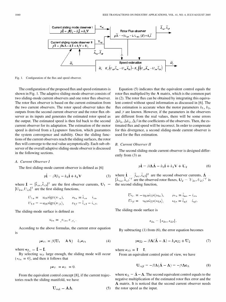
Fig. 1. Configuration of the flux and speed observer.
The configuration of the proposed flux and speed estimators isshown in Fig. 1. The adaptive sliding-mode observer consists oftwo sliding-mode current observers and one rotor flux observer.The rotor flux observer is based on the current estimation fromthe two current observers. The rotor speed observer takes theoutputs from the second current observer and the rotor flux ob-server as its inputs and generates the estimated rotor speed asthe output. The estimated speed is then fed back to the secondcurrent observer for its adaptation. The estimation of the motorspeed is derived from a Lyapunov function, which guaranteesthe system convergence and stability. Once the sliding func-tions of the current observers reach the sliding surfaces, the rotorflux will converge to the real value asymptotically. Each sub-ob-server of the overall adaptive sliding-mode observer is discussedin the following sections.
A. Current Observer I
The first sliding-mode current observer is defined as [6]
(3)
where are the first observer currents,are the first sliding functions,
The sliding-mode surface is defined as
According to the above formulas, the current error equationis
(4)
where .By selecting large enough, the sliding mode will occur
, and then it follows that
From the equivalent control concept [8], if the current trajec-tories reach the sliding manifold, we have
(5)
Equation (5) indicates that the equivalent control equals therotor flux multiplied by the matrix, which is the common partin (2). The rotor flux can be obtained by integrating this equiva-lent control without speed information as discussed in [6]. Theflux estimation is accurate when the motor parameters ,and are known. However, if the parameters in the observersare different from the real values, there will be some errors
in the coefficients of the observers. Then, the es-timated flux and speed will be incorrect. In order to compensatefor this divergence, a second sliding-mode current observer isused for the flux estimation.
B. Current Observer II
The second sliding-mode current observer is designed differ-ently from (3) as
(6)
where are the second observer currents,are the observed rotor fluxes, is
the second sliding function,
The sliding-mode surface is
By subtracting (1) from (6), the error equation becomes
(7)
where .From an equivalent control point of view, we have
(8)
where . The second equivalent control equals to thenegative multiplication of the estimated rotor flux error and the
matrix. It is noticed that the second current observer needsthe rotor speed as the input.

LI et al.: ADAPTIVE SLIDING-MODE OBSERVER FOR INDUCTION MOTOR SENSORLESS SPEED CONTROL 1041
C. Rotor Flux Observer Design
Combining the results from (5) and (8), the rotor flux observercan be constructed as
(9)
where is the observer gain matrix to be decided such that theobserver is asymptotically stable.
From (3) and (6), the equivalent controls obtained individ-ually by the two current observers will deviate from their realvalues if the motor parameters are incorrect. Consequently, therotor flux estimation based on each individual control will alsobe inaccurate. To reduce this deviation on rotor flux estimation,the rotor flux observer is designed from the combination of twoequivalent controls, where the effects of parameter variationsare largely cancelled. From (5) and (8), the error equation forthe rotor flux is
(10)
III. ADAPTIVE SPEED ESTIMATION
In order to derive the adaptive scheme, Lyapunov’s stabilitytheorem is utilized. If we consider the rotor speed as a variableparameter, the error equation of flux observer is described bythe following equation:
(11)
where
is the estimated rotor speed
The candidate Lyapunov function is defined as
(12)
where is a positive constant. We know that is positive defi-nite. The time derivative of becomes
(13)
Let be an arbitrary positive constant. With thisassumption, the above equation becomes
(14)
Letting the second term be equal to the third term in (14), wecan find the following adaptive scheme for rotor speed identifi-cation:
(15)
whereIn practice, the speed can be found by the following propor-
tional and integral adaptive scheme:
(16)
where and are the positive gains.
IV. STABLITY ANALYSIS
Since the second term is equal to the third term in (14), thetime derivative of becomes
(17)
It is apparent that (17) is negative definite. From Lyapunovstability theory, the flux observer is asymptotically stable, guar-anteeing the observed flux to converge to the real rotor flux.
V. SIMULATION RESULTS
To evaluate the proposed algorithm for the rotor flux andspeed estimation, computer simulations have been conductedusing MATLAB. The block diagram of the control system isshown in Fig. 2. To further investigate the implemental fea-sibility, the estimation and control algorithm are evaluated byhardware-in-the-loop (HIL) testing. A 1-hp induction motor wasused in the simulation and also in the experiments. The motorparameters are as follows: 1 hp, four poles, 220 V, 5 A,
, , mH, and mH.
A. Simulation Results by MATLAB
Figs. 3 and 4 show the induction motor response to a stepspeed command of 0.5 pu ( 900 r/min) where the motor pa-rameters are exactly known. The actual machine model is used

1042 IEEE TRANSACTIONS ON INDUSTRY APPLICATIONS, VOL. 41, NO. 4, JULY/AUGUST 2005
Fig. 2. System configuration for simulation and implementation.
Fig. 3. Real and estimated speed at a step speed command.
to calculate the current, flux, and speed of the motor. The ob-server model as described above is used to estimate the rotorflux and speed. Fig. 3 shows the speed command, real speed,estimated speed, and the speed estimation error. Fig. 4 showsthe real and estimated rotor flux and the flux estimation error.It can be seen that the estimated speed and flux converge to thereal values very quickly.
Fig. 4. Real and estimated rotor flux.
To study the effects of parameter variation on the speed andflux observers, the parameters in the observers are changedon purpose in the simulation. Fig. 5 shows the simulationresults when the coefficient in the observers is changed by20% from its actual value, where the flux and speed
are estimated by the proposed method, andand by the previous method using only one current

LI et al.: ADAPTIVE SLIDING-MODE OBSERVER FOR INDUCTION MOTOR SENSORLESS SPEED CONTROL 1043
Fig. 5. Coefficient k in the observer is increased by 20%. (a) � : real rotorflux; � : estimated by the proposed method; � : estimated byprevious method. (b) ! : real rotor speed; ! : estimated by the proposedmethod; ! : estimated by previous method.
sliding-mode observer as in [6]. It is noticed that even ifis incorrect, the estimated rotor flux and speed by the newobserver still converge to the real values, but in the previousmodel, there is an offset in the rotor flux estimation andfluctuation in the rotor speed estimation. The dc offset of fluxestimation by the previous method is caused by the incorrectequivalent control . If changes, the equivalent control
will detune. The integration of incorrect causesdc offset on the flux estimation, whereas in the new fluxobserver, this dc offset is cancelled by using two currentobservers. The effects of coefficient variation on the fluxand speed estimation are shown in Fig. 6. We can also observeobvious fluctuations in speed estimation. There is still anerror on the rotor flux estimation by the proposed methodas shown in Fig. 6(a), but the new method eliminates thedc offset caused by the parameter variation, which can beobserved in results simulated by the previous model.
Fig. 6. Coefficient � in the observer is increased by 20%. (a) � : real rotorflux; � : estimated by the proposed method; � : estimated byprevious method. (b) ! : real rotor flux; ! : estimated by the proposedmethod; ! : estimated by previous method.
B. HIL Evaluation Results by TI 2812 DSP
HIL evaluation is to use a computer model of the process asthe real target hardware, and on the other hand, the control andestimation algorithm are implemented in real time. The purposeof HIL is to make evaluation of the proposed algorithm as closeas possible to that which would be encountered in the real-timeimplementation. In this paper, the evaluation is performed usinga TMS320F2812 DSP. The dynamics of the electric machineare modeled by five differential equations. The control and esti-mated algorithms are implemented in 32-bit Q-math approach,interacting with the motor model rather than the real targetedphysical system.
The main advantages of this evaluation are: 1) the controlsoftware is implemented and evaluated in real time and can bedebugged very easily in the absence of motor and 2) the controlsoftware can be easily transferred to the real drive system withonly minor changes.

1044 IEEE TRANSACTIONS ON INDUSTRY APPLICATIONS, VOL. 41, NO. 4, JULY/AUGUST 2005
Fig. 7. Speed step response from�0.5 pu to 0.5 pu (curve 1: speed command! , 0.606 pu/div; curve 2: real speed ! , 0.606 pu/div; curve 3: estimated speed~! , 0.606 pu/div).
Fig. 8. Rotor flux estimation (curve 1: real flux � ; curve 2: estimated flux~� ; curve 3: estimated flux angle ~� ).
The results evaluated by HIL are shown in Figs. 7–9. Fig. 7shows the motor step response to a speed command at 0.5 pu( 900 r/min). Fig. 8 shows the real and estimated rotor flux andthe estimated flux angle. Fig. 9 shows the motor response to atrapezoidal speed command. The results show that the methodcan be successfully implemented by the fixed-point DSP.
VI. EXPERIMETAL RESULTS
In order to evaluate the performance of the proposed algo-rithm experimentally, an induction motor drive system was setup. The setup consists of a 1-hp induction motor, a power driveboard, and a DSP controller board. The external load is imposedby a hysteresis dynamometer. The experimental setup is shownin Fig. 10.
Fig. 9. Trapezoidal speed at �0.5 pu (curve 1: phase current i , 0.6 pu/div;curve 2: torque current i , 0.3 pu/div; curve 3: estimated speed ~! , 1.212pu/div).
Fig. 10. Experimental setup.
The control algorithm is implemented by a Texas InstrumentsTMS320F2812 32-bit fixed-point DSP. It has the followingfeatures:
• high-performance static CMOS technology, 150 MHz(6.67-ns cycle time);
• high-performance 32-bit CPU;• Flash devices: up to 128 K 16 Flash;• 12-bit ADC, 16 channels.The test was first performed on the motor in four-quadrant op-
eration. Fig. 11 shows the motor response to a commanded stepchange speed at 900 r/min. Fig. 12 shows the measured cur-rent and two sliding-mode observer currents. It is seen that thesliding-mode functions enforce the two observed currents to themeasured ones very closely. Once these two observer currentsconverge to the measured ones, the estimated rotor flux con-verges to the real rotor flux. The motor responses to a trapezoidalspeed command when the motor runs at no load are shown inFig. 13. To further investigate the motor transient performanceat load conditions, an external torque pu is appliedwhen the motor runs at the same trapezoidal speed commandas in Fig. 13. The waveform of speed command , estimatedspeed , torque current , and phase current are shown inFig. 14. The estimated rotor speed response to a step change ofcommand from 360 to 1260 r/min with a load torque of

LI et al.: ADAPTIVE SLIDING-MODE OBSERVER FOR INDUCTION MOTOR SENSORLESS SPEED CONTROL 1045
Fig. 11. Transient response to speed step command �900 r/min at no load(curve1: speed command! , 1091 r/min/div; curve 2: estimated speed ~! , 1091r/min/div; curve 3: torque current i , 1.5 A/div; curve 4: phase current i , 5A/div).
Fig. 12. Real and estimated currents (curve 1: measured current i , 3 A/div;curve 2: observed current i , 3 A/div; curve 3: observed current~i , 3 A/div).
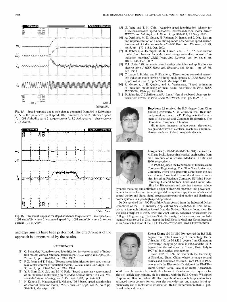
pu is shown in Fig. 15. To investigate the speed robustness, a stepdisturbance torque pu is applied and then removed atmotor speed r/min. Fig. 16 shows the estimated rotorspeed response and the torque current response. As evidencedby the testing results, the induction motor drive functions verywell by the proposed algorithm.
VII. CONCLUSION
A novel adaptive sliding-mode observer for sensorless speedcontrol of an induction motor has been presented in this paper.The proposed algorithm consists of two current observers andone rotor flux observer. The two sliding-mode current observers
Fig. 13. Transient response due to trapezoidal speed command (� 900 r/min)at no load (curve 1: speed command ! , 2182 r/min/div; curve 2: estimatedspeed ~! , 2182 r/min/div; curve 3: torque current i , 1.5 A/div; curve 4: phasecurrent i , 5 A/div).
Fig. 14. Transient response due to trapezoidal speed command (�900 r/min)atT = 0:5 pu (curve 1: speed command! , 1091 r/min/div; curve 2: estimatedspeed ~! , 1091 r/min/div; curve 3: torque current i , 1.5 A/div; curve 4: phasecurrent i , 5 A/div).
are utilized to compensate for the effects of parameter varia-tions on the rotor flux estimation. When the motor parametersare deviated from initial values by temperature or operation con-ditions, the errors of two equivalent controls from current ob-servers will be largely cancelled, which make the flux estima-tion more accurate and insensitive to parameter variations. Al-though an additional sliding-mode current observer is used, thecomplexity of the method is not increased too much. The sta-bility and convergence of the estimated flux to real rotor fluxare proved by the Lyapunov stability theory. Digital simulation
1046 IEEE TRANSACTIONS ON INDUSTRY APPLICATIONS, VOL. 41, NO. 4, JULY/AUGUST 2005
Fig. 15. Speed response due to step change command from 360 to 1260 r/minat T = 0:5 pu (curve1: real speed, 1091 r/min/div; curve 2: estimated speed~! , 1091 r/min/div; curve 3: torque current i , 1.5 A/div; curve 4: phase currenti , 5 A/div).
Fig. 16. Transient response for step disturbance torque (curve1: real speed ! ,1091 r/min/div; curve 2: estimated speed ~! , 1091 r/min/div; curve 3: torquecurrent i , 1.5 A/div).
and experiments have been performed. The effectiveness of theapproach is demonstrated by the results.
REFERENCES
[1] C. Schauder, “Adaptive speed identification for vector control of induc-tion motors without rotational transducers,” IEEE Trans. Ind. Appl., vol.28, no. 5, pp. 1054–1061, Sep./Oct. 1992.
[2] F. Z. Peng and T. Fukao, “Robust speed identification for speed-sensor-less vector control of induction motors,” IIEEE Trans. Ind. Appl., vol.30, no. 5, pp. 1234–1240, Sep./Oct. 1994.
[3] Y. R. Kim, S. K. Sul, and M.-H. Park, “Speed sensorless vector controlof an induction motor using an extended Kalman filter,” in Conf. Rec.IEEE-IAS Annu. Meeting, vol. 1, Oct. 4–9, 1992, pp. 594–599.
[4] H. Kubota, K. Matsuse, and T. Nakano, “DSP-based speed adaptive fluxobserver of induction motor,” IEEE Trans. Ind. Appl., vol. 29, no. 2, pp.344–348, Mar./Apr. 1993.
[5] G. Yang and T. H. Chin, “Adaptive-speed identification scheme fora vector-controlled speed sensorless inverter-induction motor drive,”IEEE Trans. Ind. Appl., vol. 29, no. 4, pp. 820–825, Jul./Aug. 1993.
[6] A. Derdiyok, M. K. Guven, H. Rehman, N. Inanc, and L. Xu, “Designand implementation of a new sliding-mode observer for speed-sensor-less control of induction machine,” IEEE Trans. Ind. Electron., vol. 49,no. 5, pp. 1177–1182, Oct. 2002.
[7] H. Rehman, A. Derdiyok, M. K. Guven, and L. Xu, “A new currentmodel flux observer for wide speed reange sensorless control of aninduction machine,” IEEE Trans. Ind. Electron., vol. 49, no. 6, pp.1041–1048, Dec. 2002.
[8] V. I. Utkin, “Sliding mode control design principles and applications toelectric drives,” IEEE Trans. Ind. Electron., vol. 40, no. 1, pp. 23–36,Feb. 1993.
[9] C. Lascu, I. Boldea, and F. Blaabjerg, “Direct torque control of sensor-less induction motor drives: A sliding-mode approach,” IEEE Trans. Ind.Appl., vol. 40, no. 2, pp. 582–590, Mar./Apr. 2004.
[10] P. Mehrotra, J. E. Quaico, and R. Venkatesan, “Speed estimationof induction motor using artificial neural networks,” in Proc. IEEEIECON’96, 1996, pp. 881–886.
[11] D. Schroder, C. Schaffner, and U. Lenz, “Neural-net based observers forsensorless drives,” in Proc. IEEE IECON’94, 1994, pp. 1599–1610.
Jingchuan Li received the B.S. degree from Xi’anJiaotong University, Xi’an, China, in 1993. He is cur-rently working toward the Ph.D. degree in the Depart-ment of Electrical and Computer Engineering, TheOhio State University, Columbus.
His research interests include power electronics,design and control of electrical machines, and finite-element analysis of electromagnetic devices.
Longya Xu (S’89–M’90–SM’93–F’04) received theM.S. and Ph.D. degrees in electrical engineering fromthe University of Wisconsin, Madison, in 1986 and1990, respectively.
In 1990, he joined the Department of Electrical andComputer Engineering, The Ohio State University,Columbus, where he is presently a Professor. He hasserved as a Consultant to several industrial compa-nies, including Raytheon Company, US Wind PowerCompany, General Motors, Ford, and Unique Mo-bility Inc. His research and teaching interests include
dynamic modeling and optimized design of electrical machines and power con-verters for variable-speed generating and drive systems, application of advancedcontrol theory, and digital signal processors for control of motion and distributedpower systems in super-high-speed operation.
Dr. Xu received the 1990 First Prize Paper Award from the Industrial DrivesCommittee of the IEEE Industry Applications Society (IAS). In 1991, he re-ceived a Research Initiation Award from the National Science Foundation. Hewas also a recipient of 1995, 1999, and 2004 Lumley Research Awards from theCollege of Engineering, The Ohio State University, for his research accomplish-ments. He has served as Chairman of the IAS Electric Machines Committee andas an Associate Editor of the IEEE TRANSACTIONS ON POWER ELECTRONICS.
Zheng Zhang (M’98–SM’99) received the B.S.E.E.degree from Hefei University of Technology, Hefei,China, in 1982, the M.S.E.E. degree from ChongqingUniversity, Chongqing, China, in 1985, and the Ph.D.degree from the Politecnico di Torino, Turin, Italy in1997, all in electrical engineering.
From 1985 to 1992, he was with the Universityof Shandong, Jinan, China, where he taught severalcourses and conducted research. From 1993 to 1995,he was with the Electronics Division of the FIAT Re-search Center, Turin, Italy, as an Intern Researcher.
While there, he was involved in the development of motor and drive systems forelectric vehicle applications. He is currently with the R&E Center, WhirlpoolCorporation, Benton Harbor, MI. His research interests include special motors,advanced motor controls for low-cost electronic devices, and diagnostics of ap-pliances by use of motor drive information. He has authored more than 30 pub-lished technical papers.