icans-xiv - neutronresearch.com 14th meeting of ... system and materials database for a...
TRANSCRIPT

ICANS-XIV 14th Meeting of the International Collaboration
on Advanced Neutron Sources June 14-19, 1998
Starved Rock Lodge, Utica, Illinois, USA
STATUS OF NEUTRON SCATTERING FACILITY IN jAER1 NEUTRON SCIENCE PROJECT
Y. Oyama, R. Hino, N. Watanabe, M. Mizumoto and T. Mukaiyama
Center for Neutron Science Japan Atomic Energy Research Institute
Tokai-mura, Naka-gun, Ibaraki-ken 3 19- 1195, Japan
ABSTRACT
The JAERI Neutron Science Project is aiming at construction of high power and high energy proton accelerator for conducting both basic and nuclear energy researches. Neutron scattering facility is one of the high prioritized research facilities. A plan and R&D activities for the Neutron Science Project and the neutron scattering facility considered in the project are outlined in this paper.
1. INTRODUCTION
Neutron scattering research has achieved notable successes in recent years, such as studies on crystal structures and magnetism, and is now attracting biologists -for large organic molecules such as proteins. However, a limiting factor for neutron scattering research, specially for biology, is due to the intensity of the neutron beams. High intensity of neutron beams extends research areas to the fields that have been impossible. For this context, in Europe, the European Spallation Source (ESS) with 5 MSV proton beam power is under designing, and in the USA, Spallation Neutron Source (SNS) with 1 MW at the first stage (upgraded to 4 MW) is proposed by ORNL. In Japan, the High Energy Accelerator Research Organization (KEK) is designing a spallation neutron source with 0.6 MW proton beam power as a part of the Japan Hadron Facility (JHF) project. These spahation neutron sources are dedicated to basic science.
Since the middle of 1970’s, JAERI has been carrying out R&D for the partitioning and transmutation of long-lived radio-nuclides which are produced in nuclear power generation. In 1988, the Atomic Energy Commission set the long term partitioning and transmutation R&D program “OMEGA”, i.e., ations Making Extra @in from _Actinide and fission products. In the course of discussion on proton accelerator development for the OMEGA project, it was recognized that neutron scattering community desires to have very high neutron source strength, two order of magnitude stronger than that of existing ones. This future source is also discussed in conjunction with continuation of JAERI role as a supplier in
Keywords: Neutron Science Project, Linac, Storage Ring, Neutron Scattering Facility
22
future, because J&RI has been one of major neutron suppliers for basic science community in Japan with its research reactor JRR-3M.
Combining requirements of basic and nuclear sciences, JAERI had started the Neutron Science Project in 1996. The Neutron Science Project is preparing a conceptual design for a research complex utilizing spallation neutrons, including a high intensity pulsed and cw spallation neutron sources. [ 11 This paper is describing specially a plan of neutron scattering facility of the Neutron Science Project, as well as brief description of the project itself.
2. JAERI NEUTRON SCIENCE PROJECT 2.1 Scope of Neutron Science Project
The Neutron Science Project aims at pushing researches, utilizing neutrons, for basic science and technology development of accelerator transmutation. The projects includes R&D and construction of an 8 MW (1.5 GeV, 5.3 mA) super-conducting proton linac, a 5 MW target station with compression storage rings to allow short neutron pulses for neutron scattering research, and research facilities for transmutation engineering, neutron physics, material irradiation, medical isotopes production, spallation RI beam production for exotic nuclei investigation.
Basic science in the Neutron Science Project covers the fields of structural biology for investigating the structure and dynamics of biological molecules such as protein, advanced material science (e.g., under extreme conditions), high-energy neutron science (e.g., spallation phenomena), nuclear cross-section measurements for transmutation study, heavy- ion science for creating unstable heavy nuclei through spallation, and synthesis of super heavy extremely-neutron-rich nuclei.
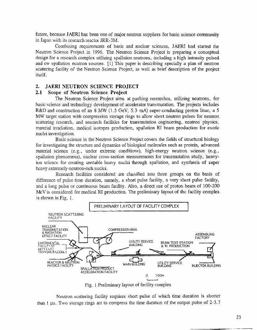
Research facilities considered are classified into three groups on the basis of difference of pulse time duration, namely, a short pulse facility, a very short pulse facility, and a long pulse or continuous beam facility. Also, a direct use of proton beam of 100-200 MeV is considered for medical RI production. The preliminary layout of the facility complex is shown in Fig. 1.
PRELIMINARY LAYOUT OF FACILITY COMPLEX I
NEUTRON SCA-ITERING FACILITY
\
REACTOR & NEUTRON PHYSICS FACILITY MAIN BUILDING
ArCFl FRATION FACII ITY
NUCLEAR TRANSMUTATION & RADIATION EFFECT FACILITY
UTILITY SERVICE BUILDING INJECTOR BUILDING
.___ - _... . ._.. .---. 0 1 OOm I I
Fig. 1 Preliminary layout of facility complex
Neutron scattering facility requires short pulse of which time duration is shorter
than 1 ps. Two storage rings act to compress the time duration of the output pulse of 2-3.7
23
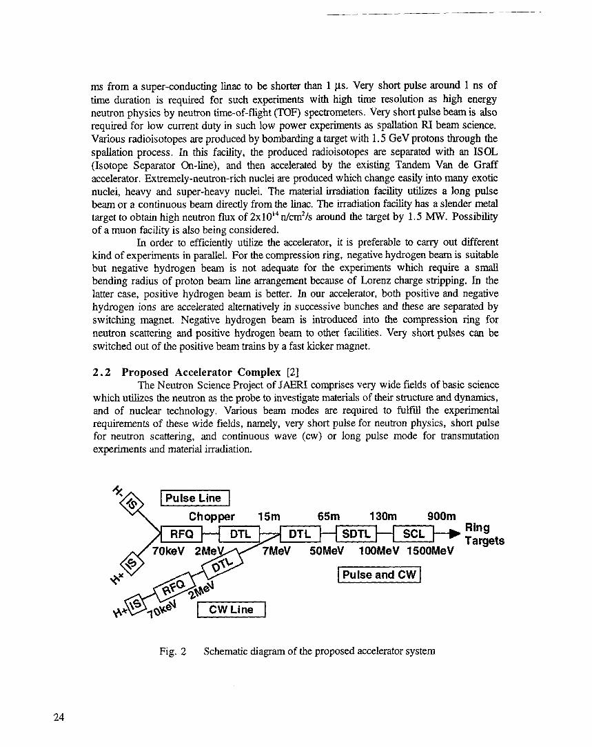

The propose accelerator system is shown in Fig.2. The proton linac is designed to deliver 8 MW beam power and at the first stage is constructed at a power of 1.5 MW (1.5 GeV, 1 mA) with pulse operation, and then gradually is increased to 8 MW and cw operation as experience of high power accelerator operation being accumulated. At the final stage, both with pulse and cw modes will be achieved. Proposed accelerator complex consists of super- conducting cavity linac more than 800 m in length and two injectors both for pulse and cw operation. The injectors consist of RPQ and DTL, and connected to superdonducting linac. For neutron scattering facility, a high energy beam transport and one (finally two) compression storage ring are considered. A preliminary specification for the proton linac is given in Table 1. The beam power with pulse mode operation is shared with 5 MW for a neutron scattering target, 2 MW for transmutation experiments and 1 MW for other experiments, in parallel, within the total beam power of 8 MW. On the other hand, for cw mode operation, a beam of several MW is required for engineering tests of a thermo-hydraulic system and materials database for a demonstration facility development for transmutation system.
Table 1 A proposed specification of the linac complex
Total beam power at targets: Proton energy: Ion source: Average current: Peak current: Linac type
RFQ:
Low p (2-1OOMeV) :
High /.3 (O.l-1.5GeV): Beam mode:
First stage: Second stage:
Repetition rate: Intermediate pulse width: Chopping factor:
8MW 1.5 Gev Negative/positive hydrogen ion sources (70 kev) 5.33 mA 30 mA(pulse)/5 mA(cw)
2 MeV for pulse/cw operations (200 MHz) DTLEDTL normal-conducting linac (200 MHz)
Super-conducting linac (600 MHz)
Pulse mode operation 2 ms CW and pulse mode (3.7 ms) operations 50 Hz 400 ns (interval 270 ns) 60%
The proton energy of 1.5 GeV was chosen considering the peak current limit of the ion source and the pulse width limit of the storage ring. The motivations for choosing a super- conducting cavity linac option are: 1) smaller beam hollow effect in large current acceleration because of large iris radius, 2) the cost reduction owing to the reduction of length of the linac which leads to the reduced investment costs and savings in operating costs, and 3) possibility for application of large current accelerator to the nuclear energy technology in future.
2.3 R&D for Accelerators The major R&D efforts are presently: 1) the beam dynamic calculation including the
high b linac, 2) the development of the negative ion source and the fabrication of high power test models with a cw-radio frequency for a quadrupole linac (RFQJ and a cw-drift tube linac (DTL), 3) the super-conducting cavity development, 4) the development of high intensity
25
proton beam storage ring, and 5) the optimization of the system design. In the course of the
super-conducting cavity development, the vertical cavity test for B =0.5 (145 MeV) was
successfully conducted in 1997 with the maximum field strength of 24 MV/m at 4.2K and 44 MV/mat 2. IK.
The proton storage ring is also one of the most important R&D items. The injection
scheme is specially critical tq compress the beam to shorter pulse less than 1 /_ts, because the
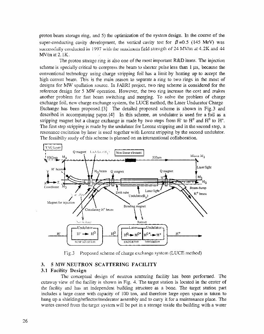
conventional technology using charge stripping foil has a limit by heating up to accept the high current beam. This is the main reason to separate a ring to two rings in the most of designs for MW spallation source. In JAERI project, two ring scheme is considered for the reference design for 5 MW operation. However, the two ring increase the cost and makes another problem for fast beam switching and merging. To solve the problem of charge exchange foil, new charge exchange system, the LUCE method, the Laser Undurator Charge Exchange has been proposed. [3] The detailed proposed scheme is shown in Fig.3 and described in accompanying paper. [4] In this scheme, an undulator is used for a foil as a stripping magnet but a charge exchange is made by two steps from H‘ to Ho and Ho to H’. The first step stripping is made by the undulator for Lorenz stripping and in the second step, a resonance excitation by laser is used together with Lorenz stripping by the second undulator. The feasibilty study of this scheme is planned on an interanational collaboration.
Mirror M 1
Fig.3 Proposed scheme of charge exchange system (LUCE method)
3. 5 MW NEUTRON SCATTERING FACILITY 3.1 Facility Design
The conceptual design of neutron scattering facility has been performed. The cutaway view of the facility is shown in Fig. 4. The target station is located in the center of the facility and has an independent building structure as a bone. The target station part includes a large crane with capacity of 100 ton, and therefore large open space is taken to hung up a shielding/reflector/moderator assembly and to carry it for a maintenance place. The wastes caused from the target system will be put in a storage inside the building with a water
26

cooling system. The experimental area is assumed to be controlled as a worker area for radiation safety, but one of beam lines is planned to be a controlled area of radioactivity for treating irradiated samples. On the other hand, the target station part is designed to be a radio- activity controlled area. The experimental area is separated from the target by the target shield that consists of an iron of 5.5-6 m in thickness and concrete of 1 m in thickness.
Fig.4 A Floor Plan of Neutron Scattering Facility in JAERI Neutron Science Project
3.2 Target/Moderator The target is one of the key equipment at the facility and requires for extensive
efforts to develop. It suffers from severe irradiation of high energy protons and neutrons, and thermal shocks by a pulsed operation. The detailed R&D strategy and status of the target/moderator development are reported separately in accompanying paper [5-81. Two types of the target systems are considered corresponding to beam power and development stage. A solid system is used at low power up to 1.5 MW and at the initial stage and a liquid mercury system for high power stage at the goal. The moderator systems are also extensively designed includin, 0 neutronics optimization study [9-121. The present design considers two coupled liquid hydrogen moderators (20K) with water pre-moderator for cold neutron sources, one decoupled and poisoned liquid hydrogen moderator (20K) for thermal source and one decoupled water moderator (room temperature) for epithermal source, as listed in Table 2.
27
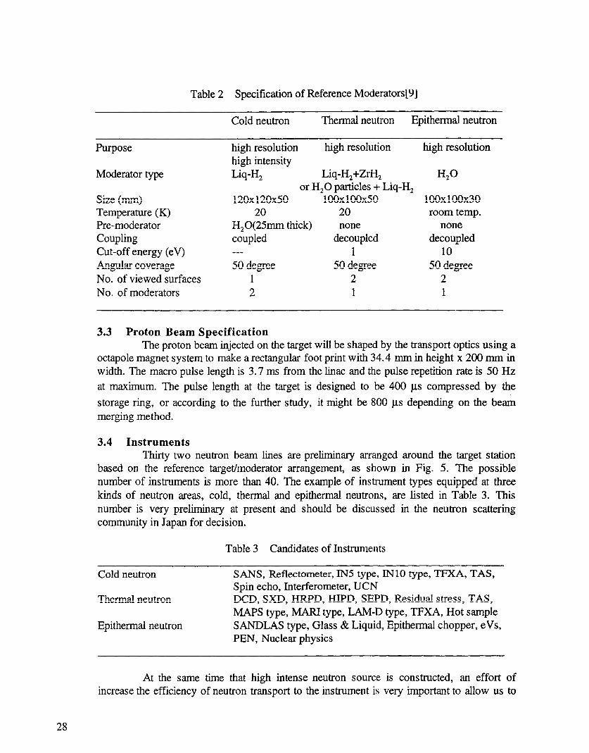
Table 2 Specification of Reference Moderators[9]
Cold neutron Thermal neutron Epithermal neutron
Purpose
Moderator type
Size (mm) Temperature (K) Pre-moderator Coupling Cut-off energy (eV) Angular coverage No. of viewed surfaces No. of moderators
high resolution high resolution high intensity Liq-H, Liq-H,+ZrH,
or H,O particles + Liq-H, 120x120x50 100x100x50
20 20 H,0(25mm thick) none coupled decoupled ___ 1 50 degree 50 degree
1 2 2 1
high resolution
w 100x100x30 room temp.
none decoupled
10 50 degree
2 1
3.3 Proton Beam Specification The proton beam injected on the target will be shaped by the transport optics using a
octapole magnet system to make a rectangular foot print with 34.4 mm in height x 200 mm in width. The macro pulse length is 3.7 ms from the linac and the pulse repetition rate is 50 Hz
at maximum. The pulse length at the target is designed to be 400 p.s compressed by the
storage ring, or according to the further study, it might be 800 us depending on the beA merging method.
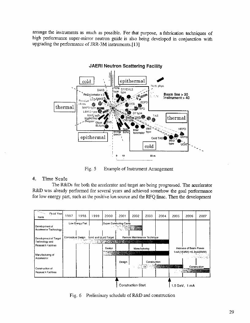
3.4 Instruments Thirty two neutron beam lines are preliminary arranged around the target station
based on the reference target/moderator arrangement, as shown in Fig. 5. The possible number of instruments is more than 40. The example of instrument types equipped at three kinds of neutron areas, cold, thermal and epithermal neutrons, are listed in Table 3. This number is very preliminary at present and should be discussed in the neutron scattering community in Japan for decision.
Table 3 Candidates of Instruments
Cold neutron
Thermal neutron
Epitherrnal neutron
SANS, Reflectometer, IN5 type, IN10 type, TFXA, TAS, Spin echo, Interferometer, UCN DCD, SXD, HRPD, HIPD, SEPD, Residual stress, TAS, MAPS type, MARI type, LAM-D type, TFXA, Hot sample SANDLAS type, Glass C?Z Liquid, Epithermal chopper, eVs, PEN, Nuclear physics
At the same time that high intense neutron source is constructed, an effort of increase the efficiency of neutron transport to the instrument is very important to allow us to
28
arrange the instruments as much as possible. For that purpose, a fabrication techniques of high performance super-mirror neutron guide is also being developed in conjunction with upgrading the performance of JRR-3M instruments.[ 131
,JAERI Neutron Scattering Facility
thermal
~ SANS’j, epithermal 1
4. Time Scale
Fig. 5 Example of Instrument Arrangement
The R&Ds for both the accelerator and target are being progressed. The accelerator R&D was already performed for several years and achieved somehow the goal performance for low energy part, such as the positive ion source and the RFQ linac. Then the development
. . . I . .’ Fscai Yeal
item
Devebpmentof
Accelerator Technology
Devebpment 01 Target
Technology and
Reseat h Fadl Rks
M%wfactuing of
Accelerator
Construction of
Reseat h Fad1 files
1997 1998 1999 2000 2001 2002 2003 2004 2005
I Low Energy Part Super Conducting Cavity
2006 2007
l I Manufaktutina I I ’ lnmase d Beam Pow!
Construction Start
Fig. 6 Prelimin‘ary schedule of R&D and construction
29
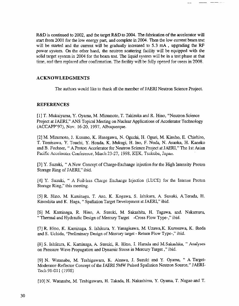
R&D is continued to 2002, and the target R&D to 2004. The fabrication of the accelerator will start from 2001 for the low energy part, and complete in 2004. Then the low current beam test will be started and the current will be gradually increased to 5.3 mA , upgrading the RF power system. On the other hand, the neutron scattering facility will be equipped with the solid target system in 2004 for the beam test. The liquid system will be in a test phase at that time, and then replaced after confirmation. The facility will be fully opened for users in 2008.
ACKNOWLEDGMENTS
The authors would like to thank all the member of JAERI Neutron Science Project.
REFERENCES
[l] T. Mukaiyama, Y. Oyama, M. Mizumoto, T. Takizuka and R. Hino, “Neutron Science Project at JAERI,” ANS Topical Meeting on Nuclear Applications of Accelerator Technology (ACCAPP’97), Nov. 16-20, 1997, Albuquerque.
[2] M. Mizumoto, J. Kusano, K. Hasegawa, N. Oguchi, H. Oguri, M. Kinsho, E. Chishiro, T. Tomisawa, Y. Touchi, Y. Honda, K. Mukugi, H. Ino, F. Noda, N. Asaoka, H. Kaneko and B. Fechner, “ A Proton Accelerator for Neutron Science Project at JAERI,” The 1st Asian Pacific Accelerator Conference, March 23-27, 1998, KEK, Tsukuba, Japan.
[3] Y. Suzuki, “ A New Concept of Charge-Exchange injection for the High Intensity Proton Storage Ring of JAERI,” ibid.
[4] Y. Suzuki, “ A Foil-less Charge Exchange Injection (LUCE) for the Intense Proton Storage Ring,” this meeting.
[5] R. Hino, M. Kaminaga, T. Aso, K. Kogawa, S. Ishikura, A. Susuki, ATerada, H. Kinoshita and K. Haga, “ Spallation Target Development at JAERI,” ibid.
[6] M. Kaminaga, R. Hino, A. Susuki, M. Sakashita, H. Tagawa, and. Nakamura, “ Thermal and Hydraulic Design of Mercury Target -Cross Flow Type-,” ibid.
[7] R. Hino, K. Kaminaga, S. Ishikura, Y. Yanagisawa, M. Uzawa,K. Kurosawa, K. Ikeda and S. Uchida, “Preliminary Design of Mercury target - Return Flow Type-,” ibid.
[8] S. Ishikura, K. Kaminaga, A Susuki, R. Hino, I. Harada and MSakashita, “ Analyses on Pressure Wave Propagation and Dynamic Stress in Mercury Target ,” ibid.
[9] N. Watanabe, M. Teshigawara, K. Aizawa, J. Suzuki and Y. Oyama, “ A Target- Moderator-Reflector Concept of the JAERI 5MW Pulsed Spallation Neutron Source,” JAERI- Tech 98-O 11 (1998)
[lo] N. Watanabe, M. Teshigawara, H. Takada, H. Nakashima, Y. Oyama, T. Nagao and T.
30
[lo] N. Watanabe, M. Teshigawara, H. Takada, H. Nakashima, Y. Oyama, T. Nagao and T. Kai , Y. Ikeda and K. Kosako, “ A Conceptual Design Study of Target-Moderator-Reflector System for JAERI 5MW Spallation Source”, this meeting.
[l I] N. Watanabe, M. Teshigawara, H. Takada, H. Nakashima, Y. Oyama, T. Nagao and T. Kai and K. Kosako, “Toward a High Efficiency Pulsed Cold Neutron Source”, ibid.
[ 121 T. Aso, A. Terada, S. Ishikura, M. Kaminaga, R. Hino and N. Watanabe, “ Structural and Hydraulic Study on Cold Source Moderator,” ibid.
[13] K. Soyama , W. Ishiyama and K. Murakami, “Enhancement of Reflectivity of Small D- Spacing Multilayer Mirrors by Ion Polishing in Combination with Ion Beam Sputtering Deposition,” ibid.
31