hydrologic & hydraulic drainage and post-construction
TRANSCRIPT
Hydrologic & Hydraulic Drainage
and
Post-Construction Stormwater Quality
Report
FOR
Artic Storage City of Oxnard, California
Prepared for:
Sakioka Farms Rive Ave, TIC
Craig Kaihara
Tel: 805.278.1703
Prepared by:
2812 Santa Monica Blvd, Suite 206
Santa Monica, CA 90404
Contact Person:
Scott Uhles P.E., LEED AP
JN 10-10268
April 2020
*This is the Drainage report that was submitted with the Construction Documents. City staff requestedthat we use this final report since it is available.
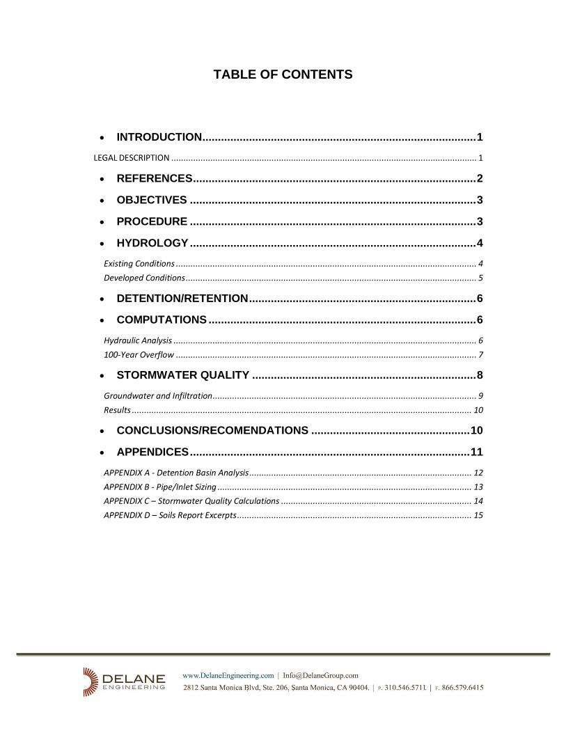
TABLE OF CONTENTS
• INTRODUCTION ........................................................................................ 1
LEGAL DESCRIPTION ............................................................................................................................. 1
• REFERENCES ........................................................................................... 2
• OBJECTIVES ............................................................................................ 3
• PROCEDURE ............................................................................................ 3
• HYDROLOGY ............................................................................................ 4
Existing Conditions ........................................................................................................................... 4
Developed Conditions ....................................................................................................................... 5
• DETENTION/RETENTION ......................................................................... 6
• COMPUTATIONS ...................................................................................... 6
Hydraulic Analysis ............................................................................................................................ 6
100-Year Overflow ........................................................................................................................... 7
• STORMWATER QUALITY ........................................................................ 8
Groundwater and Infiltration ............................................................................................................ 9
Results ........................................................................................................................................... 10
• CONCLUSIONS/RECOMENDATIONS ................................................... 10
• APPENDICES .......................................................................................... 11
APPENDIX A - Detention Basin Analysis ........................................................................................... 12
APPENDIX B - Pipe/Inlet Sizing ........................................................................................................ 13
APPENDIX C – Stormwater Quality Calculations .............................................................................. 14
APPENDIX D – Soils Report Excerpts ................................................................................................ 15
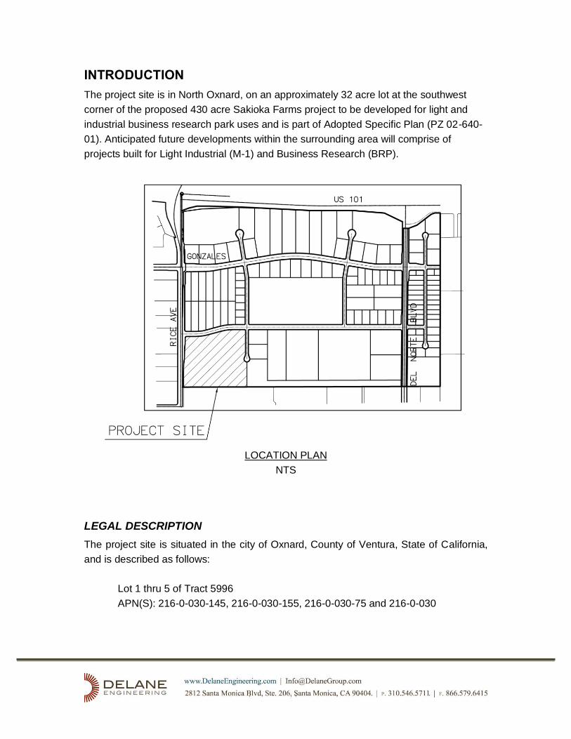
INTRODUCTION
The project site is in North Oxnard, on an approximately 32 acre lot at the southwest
corner of the proposed 430 acre Sakioka Farms project to be developed for light and
industrial business research park uses and is part of Adopted Specific Plan (PZ 02-640-
01). Anticipated future developments within the surrounding area will comprise of
projects built for Light Industrial (M-1) and Business Research (BRP).
LOCATION PLAN
NTS
LEGAL DESCRIPTION
The project site is situated in the city of Oxnard, County of Ventura, State of California,
and is described as follows:
Lot 1 thru 5 of Tract 5996
APN(S): 216-0-030-145, 216-0-030-155, 216-0-030-75 and 216-0-030

REFERENCES
• “Ventura County Watershed Protection District Hydrology Manual dated 1991.
• Master Plan of Drainage, City of Oxnard, August 2004.
• City of Oxnard and County of Ventura agreement for Sturgis Road Drain Peak flow
and storage requirements.
• Final Report of Proposed Improvements and Assessment Spread for the Northeast
Industrial Assessment District (NIAD) dated August 1985.
• Sakioka Farms Business Park Specific Plan, Langdon Wilson Architecture Planning
Interiors, January 2007.
• Ventura County Watershed Protection District Design Manual dated 1968.
• Technical Guidance Manual for Stormwater Quality Control Measures, VCWPD, 2002.
• Ventura Countywide Storm Water Quality Urban Impact Mitigation Management Plan
(SQUIMP) dated July 2000.
• City of Oxnard Standard Plans, Standard Plan Plates 54-62.
• Sakioka Tract No. 5996 Drainage Basis of Design Report, DRAFT April 2020

OBJECTIVES
The objective of this report is to present hydrologic analysis of proposed drainage
improvements to meet City of Oxnard drainage design goals consistent with the City of
Oxnard Master Plan of Drainage as well as meet Ventura Countywide Stormwater
Quality Management Programs requirements.
The City of Oxnard and the Northeast Industrial Assessment District Report (NIAD) of
1985 requires the proposed development to minimize and mitigate potential negative
impacts to the existing downstream offsite drainage facilities by requiring all
developments within the Rice Road Drain watershed to construct detention facilities to
limit peak discharges to no more than one (1) cfs per acre for events up to and including
the 100-year storm. The overall Sakioka Farms development plan includes reservoirs to
attenuate runoff attributed to developed right-of-way and common open space but
requires flow rate mitigation to be individually implemented on each lot.
The City of Oxnard requires all new development within the city to incorporate
stormwater quality control measures into the proposed improvement plans as part of the
County Storm Water Quality Urban Impact Mitigation Management Plan (SQUIMP),
NPDES Permit No. CAS004002, Order 2010-0108 for projects deemed complete prior to
October 11, 2011. The Sakioka Specific Plan is “Grandfathered” under the old permit.
PROCEDURE
This report has been prepared in accordance with the requirements of the City of Oxnard
and Ventura County regulations.
The report shall provide analysis showing how the project meets the following list of
design requirements:
a. As stated in the “Agreement for Storm Water Retention Within Rice Road Drain
Watershed" drainage from the development must provide detention facilities to
allow the release of only 1 cfs/acre during a 100-year storm event.
b. Design inlets, conveyances and conduits for a 10-year storm event.
c. Stormwater Control BMPs shall be designed per the Ventura County Technical
Guidance Manual for Stormwater Quality Control Measures, 2002.
d. Structures shall be protected from a 100-year flood event.
HYDROLOGY
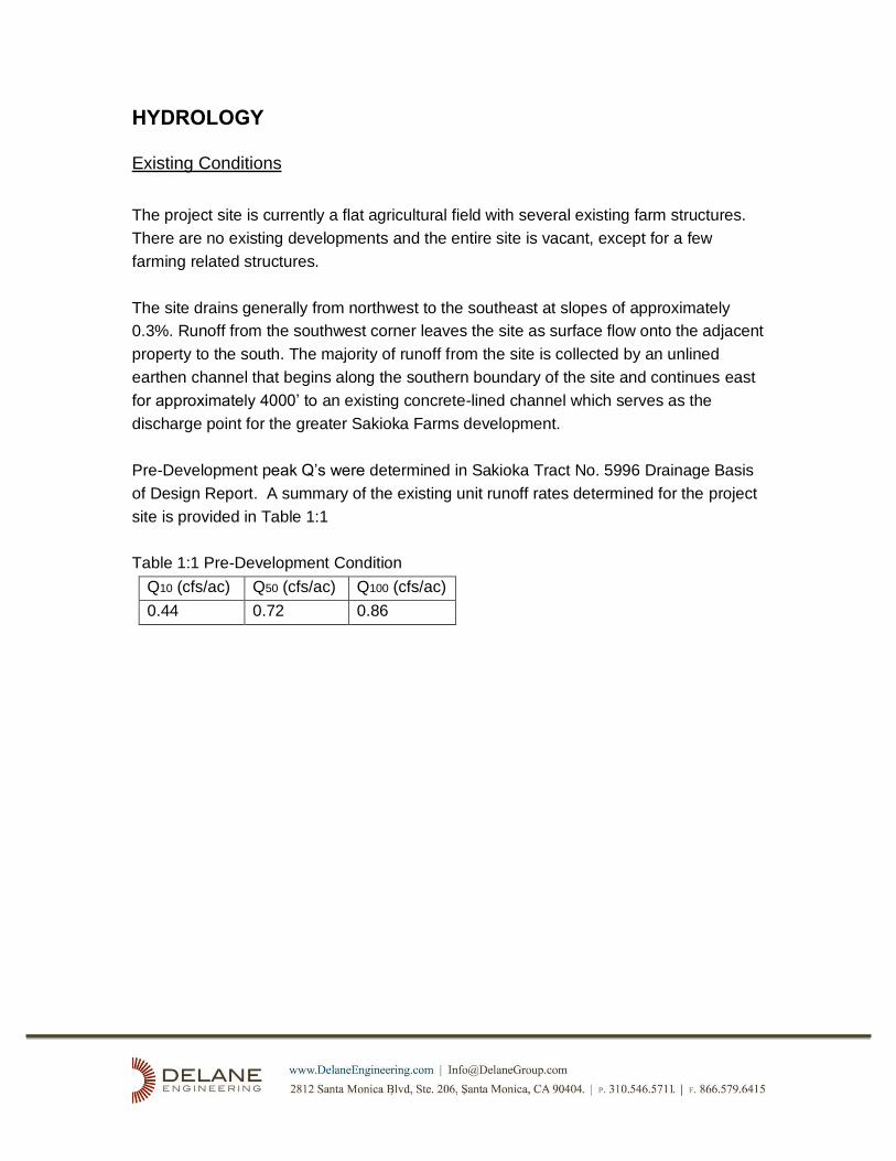
Existing Conditions
The project site is currently a flat agricultural field with several existing farm structures.
There are no existing developments and the entire site is vacant, except for a few
farming related structures.
The site drains generally from northwest to the southeast at slopes of approximately
0.3%. Runoff from the southwest corner leaves the site as surface flow onto the adjacent
property to the south. The majority of runoff from the site is collected by an unlined
earthen channel that begins along the southern boundary of the site and continues east
for approximately 4000’ to an existing concrete-lined channel which serves as the
discharge point for the greater Sakioka Farms development.
Pre-Development peak Q’s were determined in Sakioka Tract No. 5996 Drainage Basis
of Design Report. A summary of the existing unit runoff rates determined for the project
site is provided in Table 1:1
Table 1:1 Pre-Development Condition
Q10 (cfs/ac) Q50 (cfs/ac) Q100 (cfs/ac)
0.44 0.72 0.86
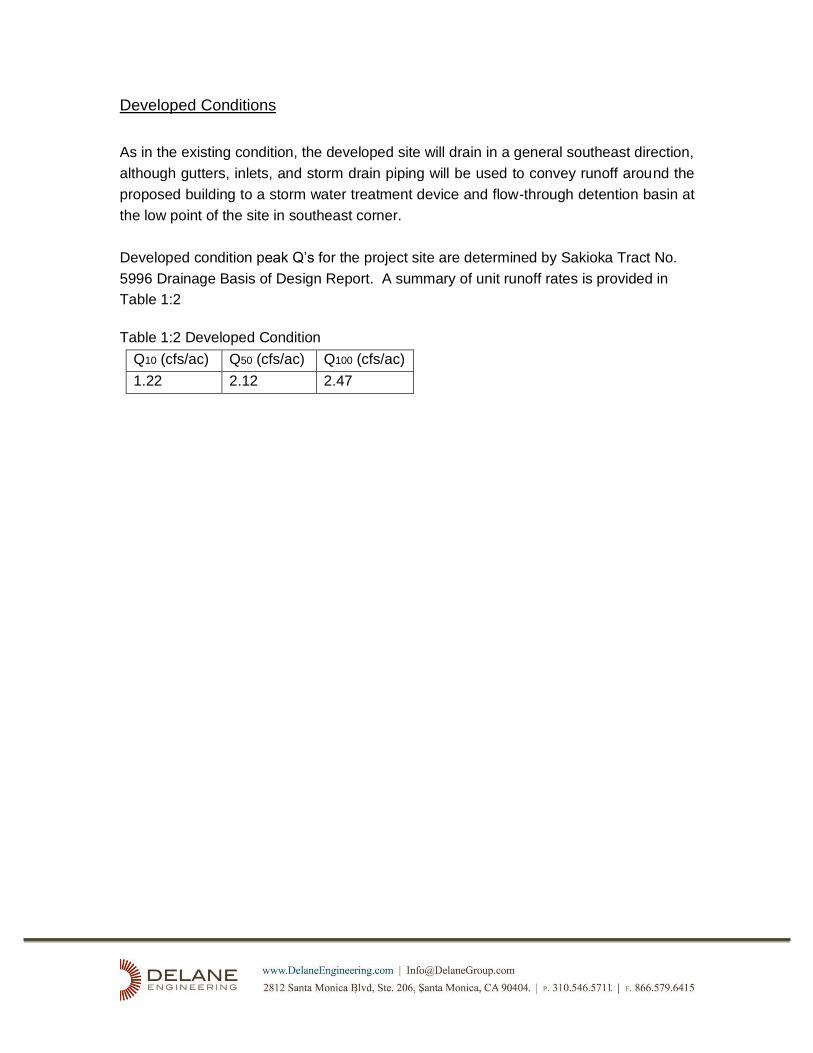
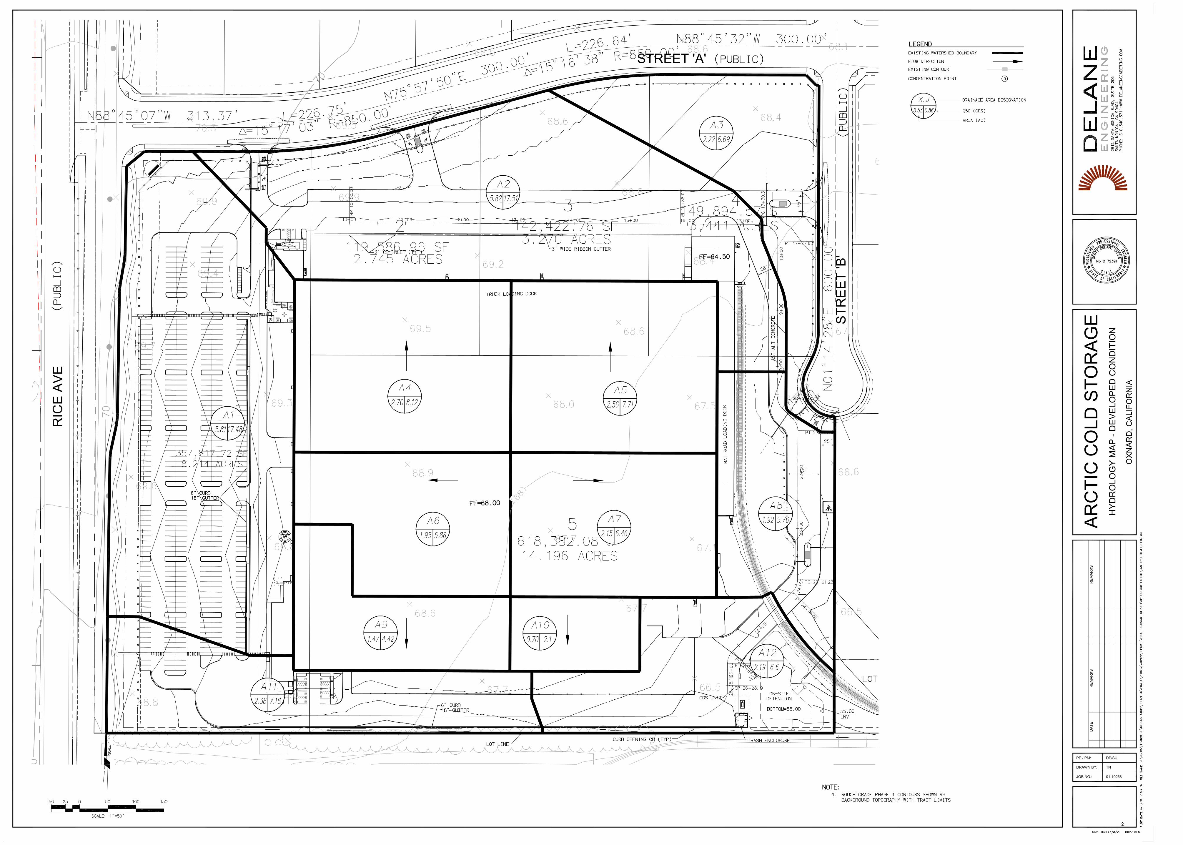
Developed Conditions
As in the existing condition, the developed site will drain in a general southeast direction,
although gutters, inlets, and storm drain piping will be used to convey runoff around the
proposed building to a storm water treatment device and flow-through detention basin at
the low point of the site in southeast corner.
Developed condition peak Q’s for the project site are determined by Sakioka Tract No.
5996 Drainage Basis of Design Report. A summary of unit runoff rates is provided in
Table 1:2
Table 1:2 Developed Condition
Q10 (cfs/ac) Q50 (cfs/ac) Q100 (cfs/ac)
1.22 2.12 2.47
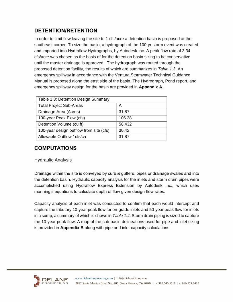
DETENTION/RETENTION
In order to limit flow leaving the site to 1 cfs/acre a detention basin is proposed at the
southeast corner. To size the basin, a hydrograph of the 100-yr storm event was created
and imported into Hydraflow Hydragraphs, by Autodesk Inc. A peak flow rate of 3.34
cfs/acre was chosen as the basis of for the detention basin sizing to be conservative
until the master drainage is approved. The hydrograph was routed through the
proposed detention facility, the results of which are summarizes in Table 1.3. An
emergency spillway in accordance with the Ventura Stormwater Technical Guidance
Manual is proposed along the east side of the basin. The Hydrograph, Pond report, and
emergency spillway design for the basin are provided in Appendix A.
Table 1.3: Detention Design Summary
Total Project Sub-Areas A
Drainage Area (Acres) 31.87
100-year Peak Flow (cfs) 106.38
Detention Volume (cu.ft) 58,432
100-year design outflow from site (cfs) 30.42
Allowable Outflow 1cfs/ca 31.87
COMPUTATIONS
Hydraulic Analysis
Drainage within the site is conveyed by curb & gutters, pipes or drainage swales and into
the detention basin. Hydraulic capacity analysis for the inlets and storm drain pipes were
accomplished using Hydraflow Express Extension by Autodesk Inc., which uses
manning’s equations to calculate depth of flow given design flow rates.
Capacity analysis of each inlet was conducted to confirm that each would intercept and
capture the tributary 10-year peak flow for on-grade inlets and 50-year peak flow for inlets
in a sump, a summary of which is shown in Table 1.4. Storm drain piping is sized to capture
the 10-year peak flow. A map of the sub-basin delineations used for pipe and inlet sizing
is provided in Appendix B along with pipe and inlet capacity calculations.
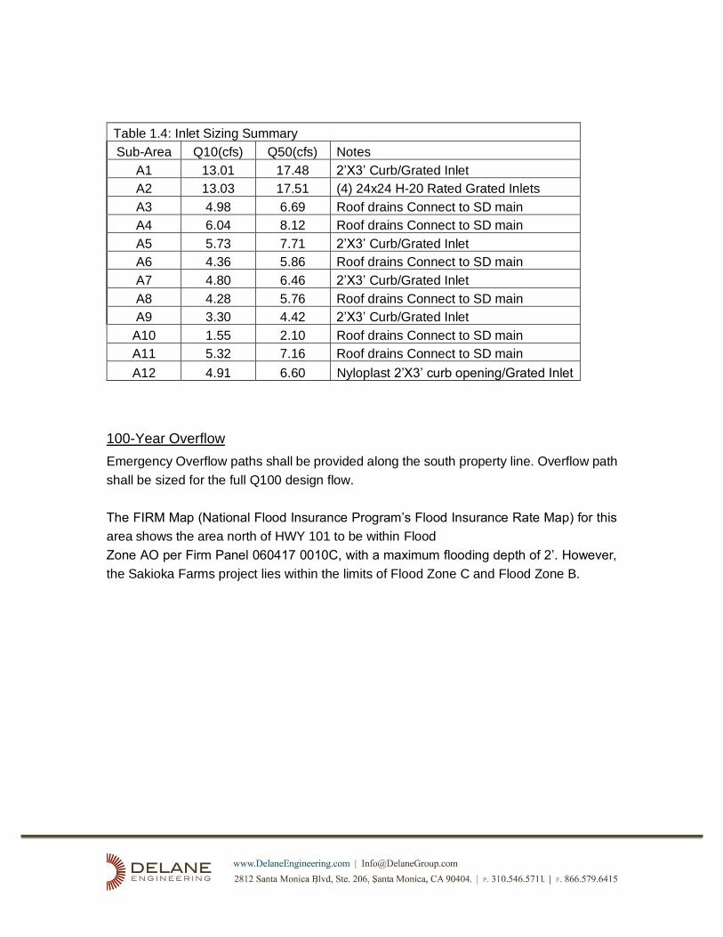
Table 1.4: Inlet Sizing Summary
Sub-Area Q10(cfs) Q50(cfs) Notes
A1 13.01 17.48 2’X3’ Curb/Grated Inlet
A2 13.03 17.51 (4) 24x24 H-20 Rated Grated Inlets
A3 4.98 6.69 Roof drains Connect to SD main
A4 6.04 8.12 Roof drains Connect to SD main
A5 5.73 7.71 2’X3’ Curb/Grated Inlet
A6 4.36 5.86 Roof drains Connect to SD main
A7 4.80 6.46 2’X3’ Curb/Grated Inlet
A8 4.28 5.76 Roof drains Connect to SD main
A9 3.30 4.42 2’X3’ Curb/Grated Inlet
A10 1.55 2.10 Roof drains Connect to SD main
A11 5.32 7.16 Roof drains Connect to SD main
A12 4.91 6.60 Nyloplast 2’X3’ curb opening/Grated Inlet
100-Year Overflow
Emergency Overflow paths shall be provided along the south property line. Overflow path
shall be sized for the full Q100 design flow.
The FIRM Map (National Flood Insurance Program’s Flood Insurance Rate Map) for this
area shows the area north of HWY 101 to be within Flood
Zone AO per Firm Panel 060417 0010C, with a maximum flooding depth of 2’. However,
the Sakioka Farms project lies within the limits of Flood Zone C and Flood Zone B.

STORMWATER QUALITY
Best Management Practice (BMP) devices for this project have been designed per the
Ventura County Technical Guidance Manual (TGM), July 2002. The Stormwater Quality
Design Flow (SQDF) is defined as 10% of the 50 year storm event, and the Stormwater
Quality Design Volume (SQDV) is defined as the volume necessary to capture and treat
80 percent or more of the average annual runoff volume from the site at the design
drawdown period.
The overall design concept was established to allow water to be treated through
treatment train methods. The “treatment train” allows for improved levels of pollutant
removals by providing more than one method of removing pollutants and providing them
in successive order. Providing more than one treatment method to treat runoff ensures
that pollutants are captured with a higher success rate. The treatment train process
begins with routine maintenance on the grounds. Each Parcel or Tract within the Specific
Plan shall detain in onsite detention basins before allowing runoff to enter the backbone
storm drain system or directly into the Regional Basin. Discharge into the Regional
Detention Basin shall be filtered through a Grassy Swale Filter before leaving the site via
the existing lined channel at the southeast corner of the Specific Plan.
The multiple opportunities to collect trash and debris and reduce peak flow levels of
each successive treatment measure ensures that the first flush from a storm is treated to
the facilities optimal capability. Additionally, the BMPs have been in an easily accessible
location for ease of maintenance and inspection. This ensures that the unit can be
maintained routinely and inspected often. Design worksheets and calculations provided
by the manufacturer of the systems used have been included as part of this report in
Appendix C.

Groundwater and Infiltration
Terracon performed infiltration testing for the site, the results of which are summarized in
a Draft report dated May 11, 2018, and provided in Appendix D. The findings establish
that Groundwater to be between 3 and 11 feet below the ground surface. Historic high
groundwater based on the Seismic Hazard Evaluation Report of the Oxnard Quadrangle,
by the State of California, Division of Mines and Geology finds it to be shallower than 10
feet below existing grade.
Seasonal High Ground Water is established at Elevation 51.
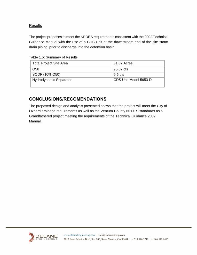
Results
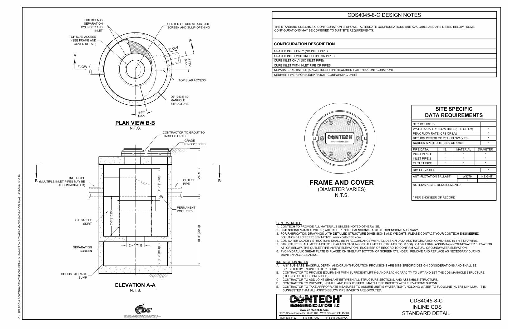
The project proposes to meet the NPDES requirements consistent with the 2002 Technical
Guidance Manual with the use of a CDS Unit at the downstream end of the site storm
drain piping, prior to discharge into the detention basin.
Table 1.5: Summary of Results
Total Project Site Area 31.87 Acres
Q50 95.87 cfs
SQDF (10% Q50) 9.6 cfs
Hydrodynamic Separator CDS Unit Model 5653-D
CONCLUSIONS/RECOMENDATIONS
The proposed design and analysis presented shows that the project will meet the City of
Oxnard drainage requirements as well as the Ventura County NPDES standards as a
Grandfathered project meeting the requirements of the Technical Guidance 2002
Manual.

APPENDICES

APPENDIX A - Detention Basin Analysis
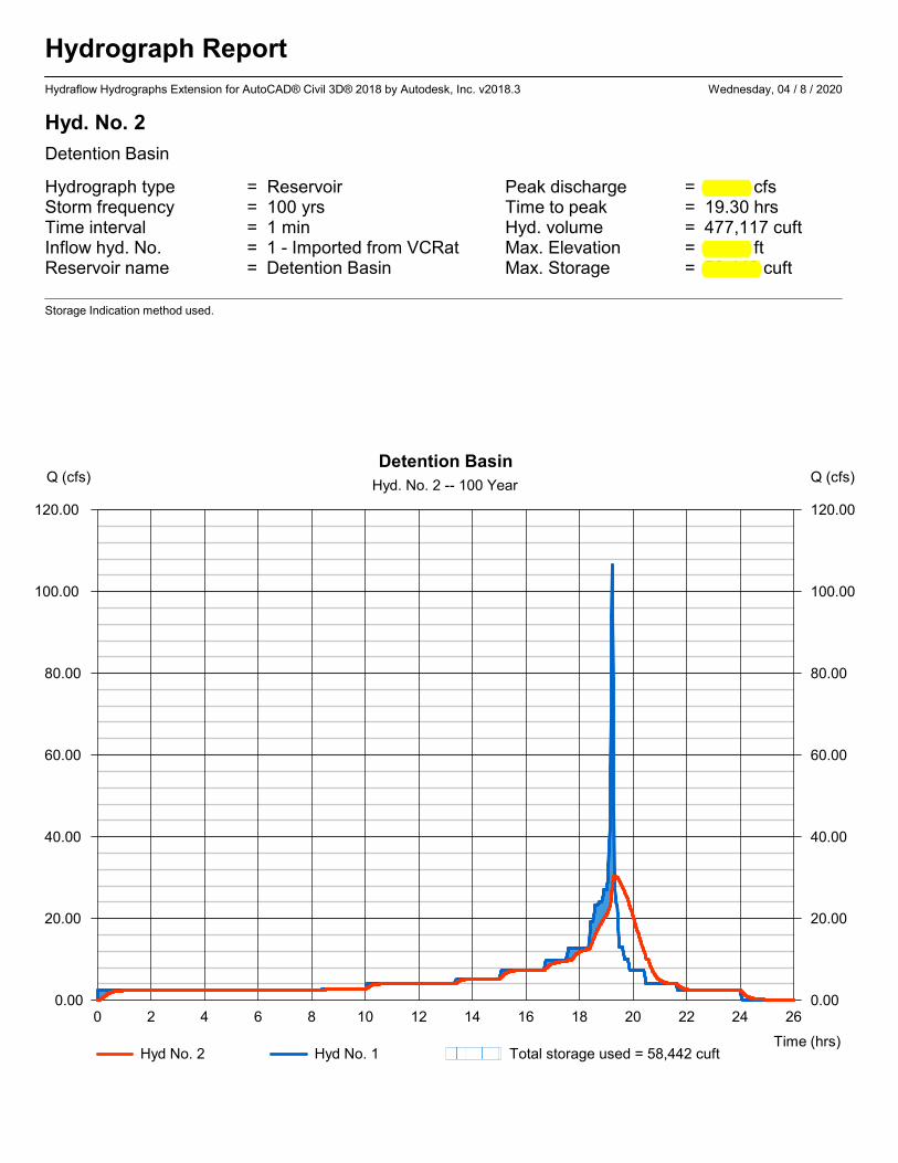
Hydrograph Report
Hydraflow Hydrographs Extension for AutoCAD® Civil 3D® 2018 by Autodesk, Inc. v2018.3 Wednesday, 04 / 8 / 2020
Hyd. No. 2
Detention Basin
Hydrograph type = Reservoir Peak discharge = 30.42 cfsStorm frequency = 100 yrs Time to peak = 19.30 hrsTime interval = 1 min Hyd. volume = 477,117 cuftInflow hyd. No. = 1 - Imported from VCRat Max. Elevation = 62.18 ftReservoir name = Detention Basin Max. Storage = 58,442 cuft
Storage Indication method used.
0 2 4 6 8 10 12 14 16 18 20 22 24 26
Q (cfs)
0.00 0.00
20.00 20.00
40.00 40.00
60.00 60.00
80.00 80.00
100.00 100.00
120.00 120.00
Q (cfs)
Time (hrs)
Detention Basin
Hyd. No. 2 -- 100 Year
Hyd No. 2 Hyd No. 1 Total storage used = 58,442 cuft
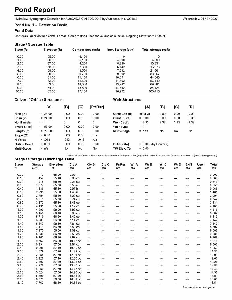
Pond ReportHydraflow Hydrographs Extension for AutoCAD® Civil 3D® 2018 by Autodesk, Inc. v2018.3 Wednesday, 04 / 8 / 2020
Pond No. 1 - Detention Basin
Pond Data
Contours -User-defined contour areas. Conic method used for volume calculation. Begining Elevation = 55.00 ft
Stage / Storage Table
Stage (ft) Elevation (ft) Contour area (sqft) Incr. Storage (cuft) Total storage (cuft)
0.00 55.00 4,100 0 01.00 56.00 5,100 4,590 4,5902.00 57.00 6,200 5,640 10,2313.00 58.00 7,300 6,742 16,9734.00 59.00 8,500 7,892 24,8645.00 60.00 9,700 9,092 33,9576.00 61.00 11,100 10,391 44,3487.00 62.00 12,500 11,792 56,1408.00 63.00 14,000 13,242 69,3819.00 64.00 15,500 14,742 84,124
10.00 65.00 17,100 16,292 100,415
Culvert / Orifice Structures Weir Structures
[A] [B] [C] [PrfRsr] [A] [B] [C] [D]
Rise (in) = 24.00 0.00 0.00 0.00
Span (in) = 24.00 0.00 0.00 0.00
No. Barrels = 1 0 0 0
Invert El. (ft) = 55.00 0.00 0.00 0.00
Length (ft) = 200.00 0.00 0.00 0.00
Slope (%) = 0.30 0.00 0.00 n/a
N-Value = .013 .013 .013 n/a
Orifice Coeff. = 0.60 0.60 0.60 0.60
Multi-Stage = n/a No No No
Crest Len (ft) Inactive 0.00 0.00 0.00
Crest El. (ft) = 0.00 0.00 0.00 0.00
Weir Coeff. = 3.33 3.33 3.33 3.33
Weir Type = 1 --- --- ---
Multi-Stage = Yes No No No
Exfil.(in/hr) = 0.000 (by Contour)
TW Elev. (ft) = 0.00
Note: Culvert/Orifice outflows are analyzed under inlet (ic) and outlet (oc) control. Weir risers checked for orifice conditions (ic) and submergence (s).
Stage / Storage / Discharge Table
Stage Storage Elevation Clv A Clv B Clv C PrfRsr Wr A Wr B Wr C Wr D Exfil User Totalft cuft ft cfs cfs cfs cfs cfs cfs cfs cfs cfs cfs cfs
0.00 0 55.00 0.00 --- --- --- --- --- --- --- --- --- 0.0000.10 459 55.10 0.06 oc --- --- --- --- --- --- --- --- --- 0.0600.20 918 55.20 0.25 oc --- --- --- --- --- --- --- --- --- 0.2490.30 1,377 55.30 0.55 ic --- --- --- --- --- --- --- --- --- 0.5530.40 1,836 55.40 0.97 ic --- --- --- --- --- --- --- --- --- 0.9660.50 2,295 55.50 1.48 ic --- --- --- --- --- --- --- --- --- 1.4810.60 2,754 55.60 2.09 oc --- --- --- --- --- --- --- --- --- 2.0940.70 3,213 55.70 2.74 oc --- --- --- --- --- --- --- --- --- 2.7440.80 3,672 55.80 3.43 oc --- --- --- --- --- --- --- --- --- 3.4310.90 4,131 55.90 4.17 oc --- --- --- --- --- --- --- --- --- 4.1651.00 4,590 56.00 4.92 oc --- --- --- --- --- --- --- --- --- 4.9161.10 5,155 56.10 5.66 oc --- --- --- --- --- --- --- --- --- 5.6621.20 5,719 56.20 6.42 oc --- --- --- --- --- --- --- --- --- 6.4191.30 6,283 56.30 7.14 oc --- --- --- --- --- --- --- --- --- 7.1421.40 6,847 56.40 7.84 oc --- --- --- --- --- --- --- --- --- 7.8431.50 7,411 56.50 8.50 oc --- --- --- --- --- --- --- --- --- 8.5021.60 7,975 56.60 9.09 oc --- --- --- --- --- --- --- --- --- 9.0881.70 8,539 56.70 9.59 oc --- --- --- --- --- --- --- --- --- 9.5881.80 9,103 56.80 9.97 oc --- --- --- --- --- --- --- --- --- 9.9681.90 9,667 56.90 10.16 oc --- --- --- --- --- --- --- --- --- 10.162.00 10,231 57.00 9.81 oc --- --- --- --- --- --- --- --- --- 9.8062.10 10,905 57.10 10.59 oc --- --- --- --- --- --- --- --- --- 10.592.20 11,579 57.20 11.32 oc --- --- --- --- --- --- --- --- --- 11.322.30 12,254 57.30 12.01 oc --- --- --- --- --- --- --- --- --- 12.012.40 12,928 57.40 12.66 oc --- --- --- --- --- --- --- --- --- 12.662.50 13,602 57.50 13.28 oc --- --- --- --- --- --- --- --- --- 13.282.60 14,276 57.60 13.87 oc --- --- --- --- --- --- --- --- --- 13.872.70 14,950 57.70 14.43 oc --- --- --- --- --- --- --- --- --- 14.432.80 15,624 57.80 14.98 oc --- --- --- --- --- --- --- --- --- 14.982.90 16,299 57.90 15.51 oc --- --- --- --- --- --- --- --- --- 15.513.00 16,973 58.00 16.01 oc --- --- --- --- --- --- --- --- --- 16.013.10 17,762 58.10 16.51 oc --- --- --- --- --- --- --- --- --- 16.51
Continues on next page...
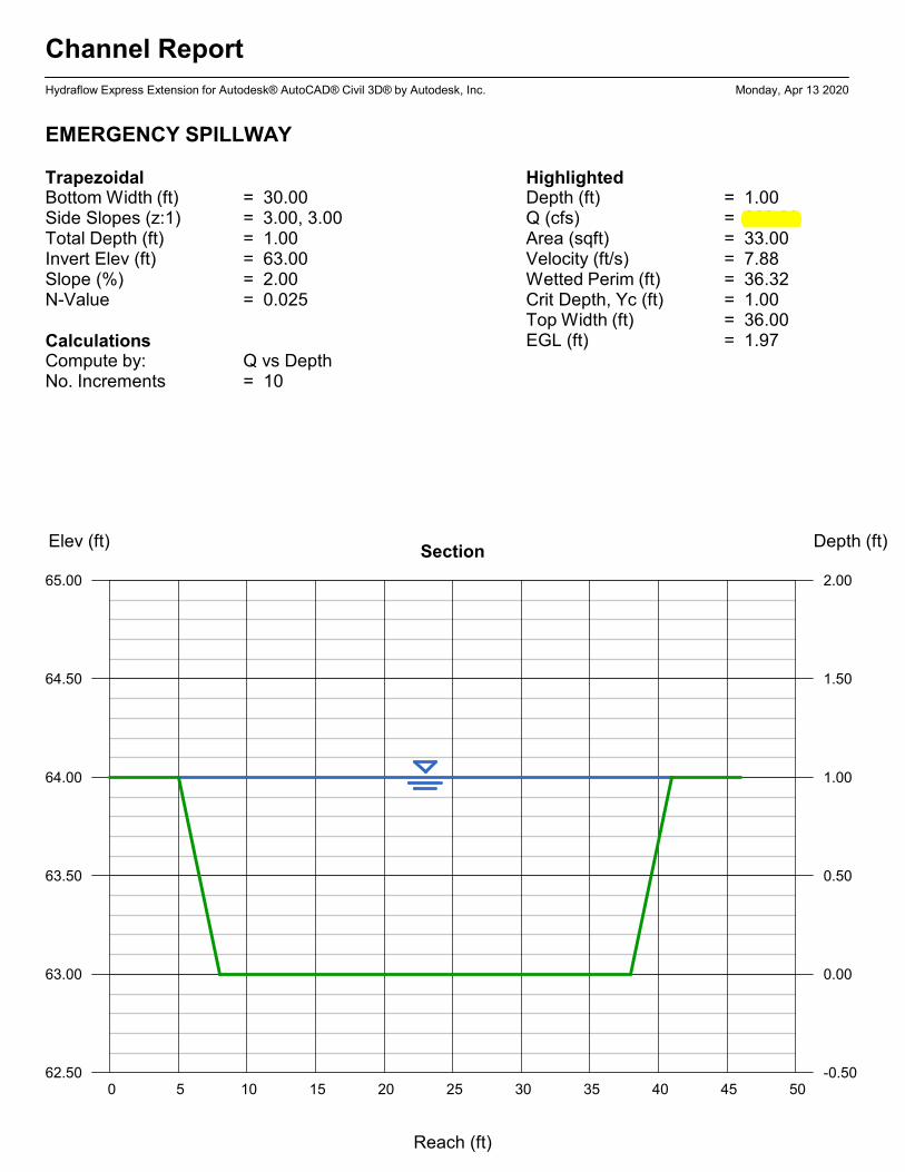
Channel Report
Hydraflow Express Extension for Autodesk® AutoCAD® Civil 3D® by Autodesk, Inc. Monday, Apr 13 2020
EMERGENCY SPILLWAY
TrapezoidalBottom Width (ft) = 30.00Side Slopes (z:1) = 3.00, 3.00Total Depth (ft) = 1.00Invert Elev (ft) = 63.00Slope (%) = 2.00N-Value = 0.025
CalculationsCompute by: Q vs DepthNo. Increments = 10
HighlightedDepth (ft) = 1.00Q (cfs) = 260.20Area (sqft) = 33.00Velocity (ft/s) = 7.88Wetted Perim (ft) = 36.32Crit Depth, Yc (ft) = 1.00Top Width (ft) = 36.00EGL (ft) = 1.97
0 5 10 15 20 25 30 35 40 45 50
Elev (ft) Depth (ft)Section
62.50 -0.50
63.00 0.00
63.50 0.50
64.00 1.00
64.50 1.50
65.00 2.00
Reach (ft)

Detention Basin
Stage / Storage / Discharge Table
Stage Storage Elevation Clv A Clv B Clv C PrfRsr Wr A Wr B Wr C Wr D Exfil User Totalft cuft ft cfs cfs cfs cfs cfs cfs cfs cfs cfs cfs cfs
3.20 18,551 58.20 16.99 oc --- --- --- --- --- --- --- --- --- 16.993.30 19,340 58.30 17.45 oc --- --- --- --- --- --- --- --- --- 17.453.40 20,129 58.40 17.90 oc --- --- --- --- --- --- --- --- --- 17.903.50 20,919 58.50 18.35 oc --- --- --- --- --- --- --- --- --- 18.353.60 21,708 58.60 18.78 oc --- --- --- --- --- --- --- --- --- 18.783.70 22,497 58.70 19.20 oc --- --- --- --- --- --- --- --- --- 19.203.80 23,286 58.80 19.61 oc --- --- --- --- --- --- --- --- --- 19.613.90 24,075 58.90 20.02 oc --- --- --- --- --- --- --- --- --- 20.024.00 24,864 59.00 20.41 oc --- --- --- --- --- --- --- --- --- 20.414.10 25,774 59.10 20.80 oc --- --- --- --- --- --- --- --- --- 20.804.20 26,683 59.20 21.18 oc --- --- --- --- --- --- --- --- --- 21.184.30 27,592 59.30 21.56 oc --- --- --- --- --- --- --- --- --- 21.564.40 28,501 59.40 21.93 oc --- --- --- --- --- --- --- --- --- 21.934.50 29,411 59.50 22.29 oc --- --- --- --- --- --- --- --- --- 22.294.60 30,320 59.60 22.65 oc --- --- --- --- --- --- --- --- --- 22.654.70 31,229 59.70 23.00 oc --- --- --- --- --- --- --- --- --- 23.004.80 32,138 59.80 23.34 oc --- --- --- --- --- --- --- --- --- 23.344.90 33,048 59.90 23.68 oc --- --- --- --- --- --- --- --- --- 23.685.00 33,957 60.00 24.02 oc --- --- --- --- --- --- --- --- --- 24.025.10 34,996 60.10 24.35 oc --- --- --- --- --- --- --- --- --- 24.355.20 36,035 60.20 24.68 oc --- --- --- --- --- --- --- --- --- 24.685.30 37,074 60.30 25.00 oc --- --- --- --- --- --- --- --- --- 25.005.40 38,113 60.40 25.32 oc --- --- --- --- --- --- --- --- --- 25.325.50 39,152 60.50 25.63 oc --- --- --- --- --- --- --- --- --- 25.635.60 40,192 60.60 25.95 oc --- --- --- --- --- --- --- --- --- 25.955.70 41,231 60.70 26.25 oc --- --- --- --- --- --- --- --- --- 26.255.80 42,270 60.80 26.56 oc --- --- --- --- --- --- --- --- --- 26.565.90 43,309 60.90 26.86 oc --- --- --- --- --- --- --- --- --- 26.866.00 44,348 61.00 27.15 oc --- --- --- --- --- --- --- --- --- 27.156.10 45,527 61.10 27.45 oc --- --- --- --- --- --- --- --- --- 27.456.20 46,706 61.20 27.74 oc --- --- --- --- --- --- --- --- --- 27.746.30 47,886 61.30 28.02 oc --- --- --- --- --- --- --- --- --- 28.026.40 49,065 61.40 28.31 oc --- --- --- --- --- --- --- --- --- 28.316.50 50,244 61.50 28.59 oc --- --- --- --- --- --- --- --- --- 28.596.60 51,423 61.60 28.87 oc --- --- --- --- --- --- --- --- --- 28.876.70 52,602 61.70 29.15 oc --- --- --- --- --- --- --- --- --- 29.156.80 53,781 61.80 29.42 oc --- --- --- --- --- --- --- --- --- 29.426.90 54,961 61.90 29.69 oc --- --- --- --- --- --- --- --- --- 29.697.00 56,140 62.00 29.96 oc --- --- --- --- --- --- --- --- --- 29.967.10 57,464 62.10 30.23 oc --- --- --- --- --- --- --- --- --- 30.237.20 58,788 62.20 30.49 oc --- --- --- --- --- --- --- --- --- 30.497.30 60,112 62.30 30.75 oc --- --- --- --- --- --- --- --- --- 30.757.40 61,437 62.40 31.01 oc --- --- --- --- --- --- --- --- --- 31.017.50 62,761 62.50 31.27 oc --- --- --- --- --- --- --- --- --- 31.277.60 64,085 62.60 31.52 oc --- --- --- --- --- --- --- --- --- 31.527.70 65,409 62.70 31.78 oc --- --- --- --- --- --- --- --- --- 31.787.80 66,733 62.80 32.03 oc --- --- --- --- --- --- --- --- --- 32.037.90 68,057 62.90 32.28 oc --- --- --- --- --- --- --- --- --- 32.288.00 69,381 63.00 32.52 oc --- --- --- --- --- --- --- --- --- 32.528.10 70,856 63.10 32.77 oc --- --- --- --- --- --- --- --- --- 32.778.20 72,330 63.20 33.01 oc --- --- --- --- --- --- --- --- --- 33.018.30 73,804 63.30 33.26 oc --- --- --- --- --- --- --- --- --- 33.268.40 75,278 63.40 33.50 oc --- --- --- --- --- --- --- --- --- 33.508.50 76,753 63.50 33.73 oc --- --- --- --- --- --- --- --- --- 33.738.60 78,227 63.60 33.97 oc --- --- --- --- --- --- --- --- --- 33.978.70 79,701 63.70 34.21 oc --- --- --- --- --- --- --- --- --- 34.218.80 81,175 63.80 34.44 oc --- --- --- --- --- --- --- --- --- 34.448.90 82,649 63.90 34.67 oc --- --- --- --- --- --- --- --- --- 34.679.00 84,124 64.00 34.90 oc --- --- --- --- --- --- --- --- --- 34.909.10 85,753 64.10 35.13 oc --- --- --- --- --- --- --- --- --- 35.139.20 87,382 64.20 35.36 oc --- --- --- --- --- --- --- --- --- 35.369.30 89,011 64.30 35.58 oc --- --- --- --- --- --- --- --- --- 35.589.40 90,640 64.40 35.81 oc --- --- --- --- --- --- --- --- --- 35.819.50 92,270 64.50 36.03 oc --- --- --- --- --- --- --- --- --- 36.039.60 93,899 64.60 36.25 oc --- --- --- --- --- --- --- --- --- 36.259.70 95,528 64.70 36.47 oc --- --- --- --- --- --- --- --- --- 36.479.80 97,157 64.80 36.69 oc --- --- --- --- --- --- --- --- --- 36.699.90 98,786 64.90 36.91 oc --- --- --- --- --- --- --- --- --- 36.91
10.00 100,415 65.00 37.13 oc --- --- --- --- --- --- --- --- --- 37.13
...End

APPENDIX B - Pipe/Inlet Sizing
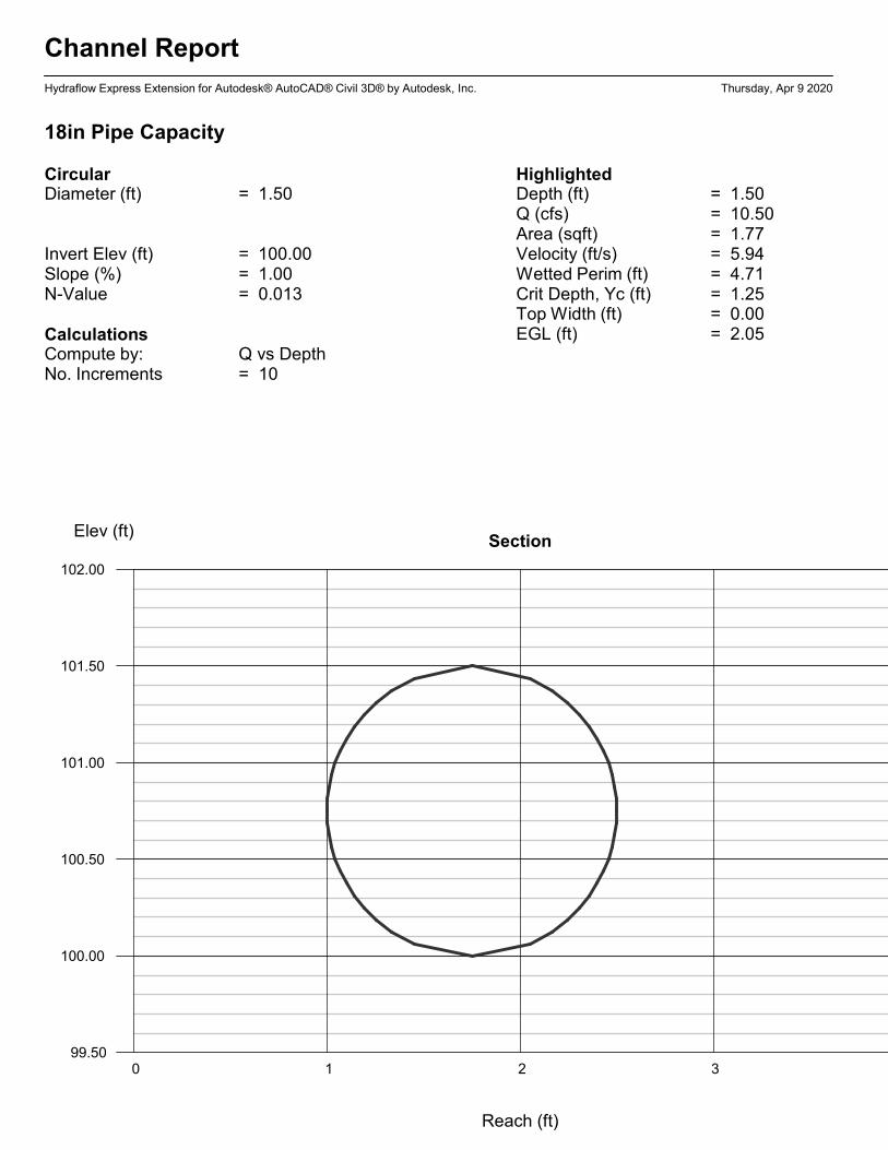
Channel Report
Hydraflow Express Extension for Autodesk® AutoCAD® Civil 3D® by Autodesk, Inc. Thursday, Apr 9 2020
18in Pipe Capacity
CircularDiameter (ft) = 1.50
Invert Elev (ft) = 100.00Slope (%) = 1.00N-Value = 0.013
CalculationsCompute by: Q vs DepthNo. Increments = 10
HighlightedDepth (ft) = 1.50Q (cfs) = 10.50Area (sqft) = 1.77Velocity (ft/s) = 5.94Wetted Perim (ft) = 4.71Crit Depth, Yc (ft) = 1.25Top Width (ft) = 0.00EGL (ft) = 2.05
0 1 2 3
Elev (ft)Section
99.50
100.00
100.50
101.00
101.50
102.00
Reach (ft)
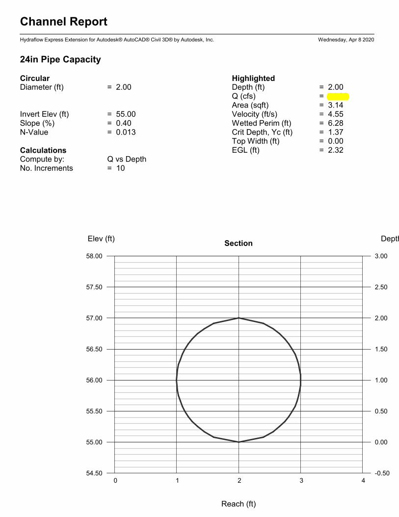
Channel Report
Hydraflow Express Extension for Autodesk® AutoCAD® Civil 3D® by Autodesk, Inc. Wednesday, Apr 8 2020
24in Pipe Capacity
CircularDiameter (ft) = 2.00
Invert Elev (ft) = 55.00Slope (%) = 0.40N-Value = 0.013
CalculationsCompute by: Q vs DepthNo. Increments = 10
HighlightedDepth (ft) = 2.00Q (cfs) = 14.30Area (sqft) = 3.14Velocity (ft/s) = 4.55Wetted Perim (ft) = 6.28Crit Depth, Yc (ft) = 1.37Top Width (ft) = 0.00EGL (ft) = 2.32
0 1 2 3 4
Elev (ft) Depth (ft)Section
54.50 -0.50
55.00 0.00
55.50 0.50
56.00 1.00
56.50 1.50
57.00 2.00
57.50 2.50
58.00 3.00
Reach (ft)
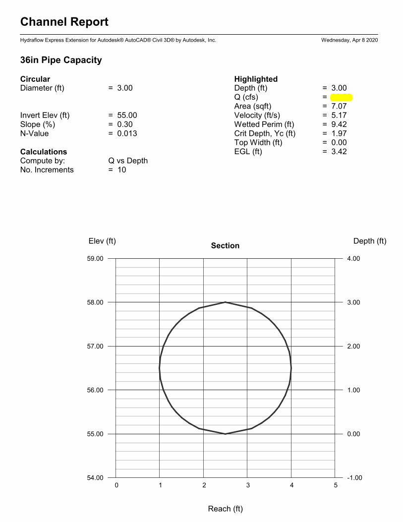
Channel Report
Hydraflow Express Extension for Autodesk® AutoCAD® Civil 3D® by Autodesk, Inc. Wednesday, Apr 8 2020
36in Pipe Capacity
CircularDiameter (ft) = 3.00
Invert Elev (ft) = 55.00Slope (%) = 0.30N-Value = 0.013
CalculationsCompute by: Q vs DepthNo. Increments = 10
HighlightedDepth (ft) = 3.00Q (cfs) = 36.53Area (sqft) = 7.07Velocity (ft/s) = 5.17Wetted Perim (ft) = 9.42Crit Depth, Yc (ft) = 1.97Top Width (ft) = 0.00EGL (ft) = 3.42
0 1 2 3 4 5
Elev (ft) Depth (ft)Section
54.00 -1.00
55.00 0.00
56.00 1.00
57.00 2.00
58.00 3.00
59.00 4.00
Reach (ft)

Channel Report
Hydraflow Express Extension for Autodesk® AutoCAD® Civil 3D® by Autodesk, Inc. Wednesday, Apr 8 2020
48in Pipe Capacity
CircularDiameter (ft) = 4.00
Invert Elev (ft) = 55.00Slope (%) = 0.30N-Value = 0.013
CalculationsCompute by: Q vs DepthNo. Increments = 10
HighlightedDepth (ft) = 4.00Q (cfs) = 78.68Area (sqft) = 12.57Velocity (ft/s) = 6.26Wetted Perim (ft) = 12.57Crit Depth, Yc (ft) = 2.69Top Width (ft) = 0.00EGL (ft) = 4.61
0 1 2 3 4 5 6
Elev (ft) Depth (ft)Section
54.00 -1.00
55.00 0.00
56.00 1.00
57.00 2.00
58.00 3.00
59.00 4.00
60.00 5.00
Reach (ft)
Channel Report
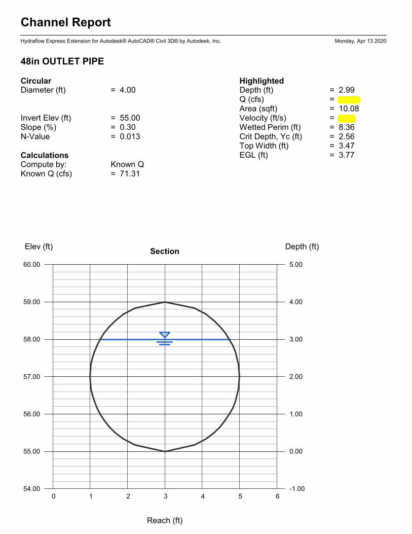
Hydraflow Express Extension for Autodesk® AutoCAD® Civil 3D® by Autodesk, Inc. Monday, Apr 13 2020
48in OUTLET PIPE
CircularDiameter (ft) = 4.00
Invert Elev (ft) = 55.00Slope (%) = 0.30N-Value = 0.013
CalculationsCompute by: Known QKnown Q (cfs) = 71.31
HighlightedDepth (ft) = 2.99Q (cfs) = 71.31Area (sqft) = 10.08Velocity (ft/s) = 7.07Wetted Perim (ft) = 8.36Crit Depth, Yc (ft) = 2.56Top Width (ft) = 3.47EGL (ft) = 3.77
0 1 2 3 4 5 6
Elev (ft) Depth (ft)Section
54.00 -1.00
55.00 0.00
56.00 1.00
57.00 2.00
58.00 3.00
59.00 4.00
60.00 5.00
Reach (ft)

Inlet Report
Hydraflow Express Extension for Autodesk® AutoCAD® Civil 3D® by Autodesk, Inc. Sunday, Nov 17 2019
CB A1
Combination InletLocation = SagCurb Length (ft) = 3.00Throat Height (in) = 6.00Grate Area (sqft) = 1.00Grate Width (ft) = 2.00Grate Length (ft) = 3.00
GutterSlope, Sw (ft/ft) = 0.050Slope, Sx (ft/ft) = 0.050Local Depr (in) = -0-Gutter Width (ft) = 1.50Gutter Slope (%) = -0-Gutter n-value = -0-
CalculationsCompute by: Known QQ (cfs) = 3.64
HighlightedQ Total (cfs) = 3.64Q Capt (cfs) = 3.64Q Bypass (cfs) = -0-Depth at Inlet (in) = 3.52Efficiency (%) = 100Gutter Spread (ft) = 5.87Gutter Vel (ft/s) = -0-Bypass Spread (ft) = -0-Bypass Depth (in) = -0-
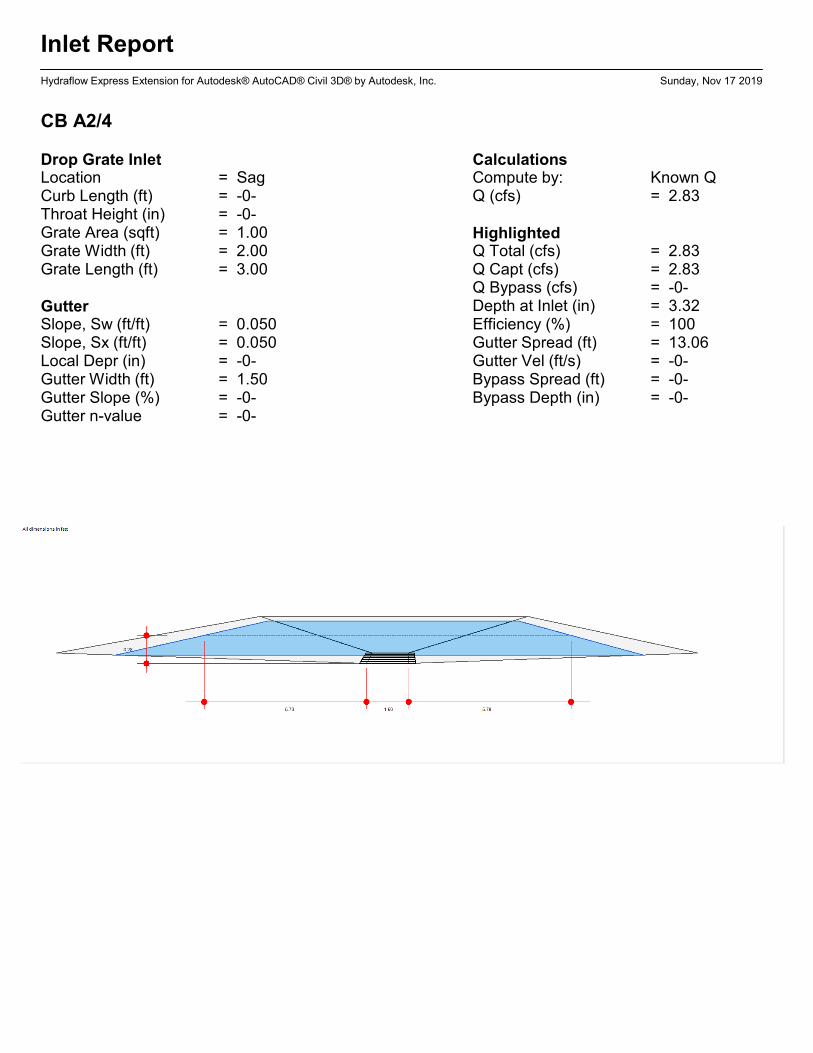
Inlet Report
Hydraflow Express Extension for Autodesk® AutoCAD® Civil 3D® by Autodesk, Inc. Sunday, Nov 17 2019
CB A2/4
Drop Grate InletLocation = SagCurb Length (ft) = -0-Throat Height (in) = -0-Grate Area (sqft) = 1.00Grate Width (ft) = 2.00Grate Length (ft) = 3.00
GutterSlope, Sw (ft/ft) = 0.050Slope, Sx (ft/ft) = 0.050Local Depr (in) = -0-Gutter Width (ft) = 1.50Gutter Slope (%) = -0-Gutter n-value = -0-
CalculationsCompute by: Known QQ (cfs) = 2.83
HighlightedQ Total (cfs) = 2.83Q Capt (cfs) = 2.83Q Bypass (cfs) = -0-Depth at Inlet (in) = 3.32Efficiency (%) = 100Gutter Spread (ft) = 13.06Gutter Vel (ft/s) = -0-Bypass Spread (ft) = -0-Bypass Depth (in) = -0-
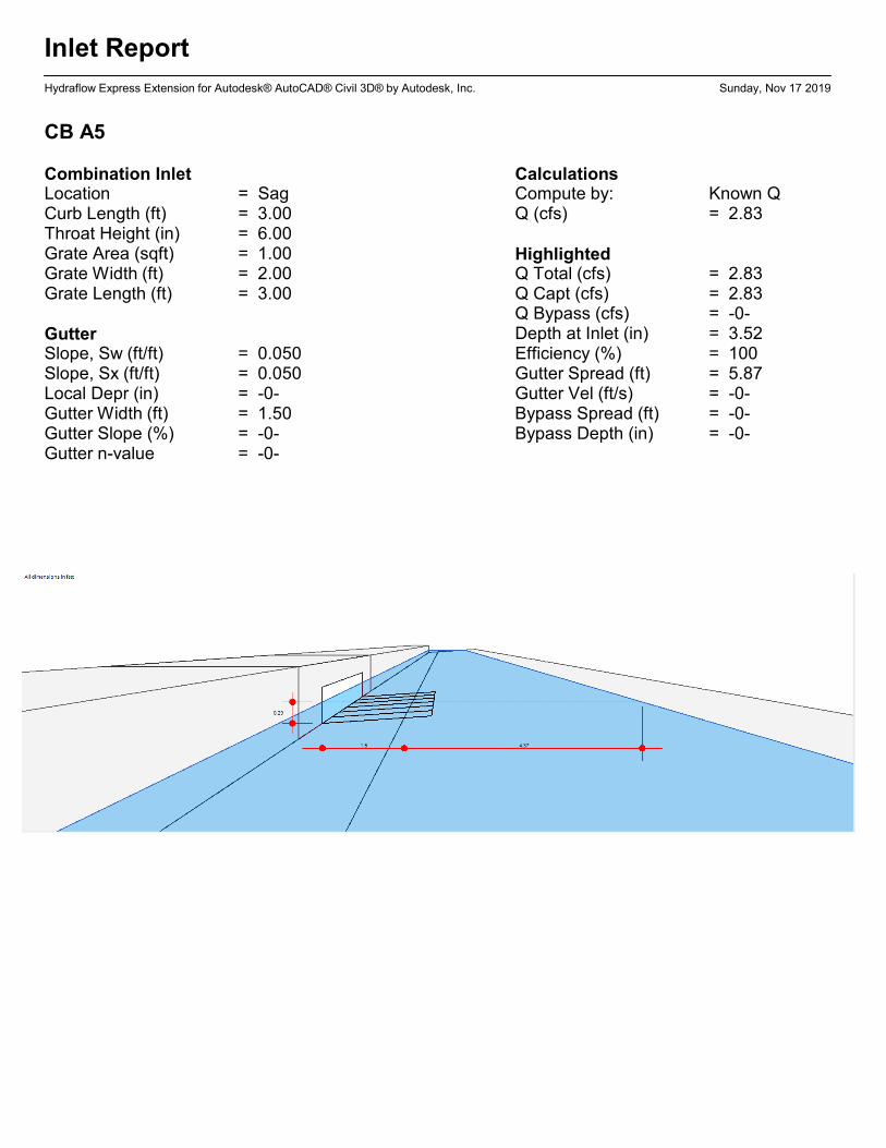
Inlet Report
Hydraflow Express Extension for Autodesk® AutoCAD® Civil 3D® by Autodesk, Inc. Sunday, Nov 17 2019
CB A5
Combination InletLocation = SagCurb Length (ft) = 3.00Throat Height (in) = 6.00Grate Area (sqft) = 1.00Grate Width (ft) = 2.00Grate Length (ft) = 3.00
GutterSlope, Sw (ft/ft) = 0.050Slope, Sx (ft/ft) = 0.050Local Depr (in) = -0-Gutter Width (ft) = 1.50Gutter Slope (%) = -0-Gutter n-value = -0-
CalculationsCompute by: Known QQ (cfs) = 2.83
HighlightedQ Total (cfs) = 2.83Q Capt (cfs) = 2.83Q Bypass (cfs) = -0-Depth at Inlet (in) = 3.52Efficiency (%) = 100Gutter Spread (ft) = 5.87Gutter Vel (ft/s) = -0-Bypass Spread (ft) = -0-Bypass Depth (in) = -0-
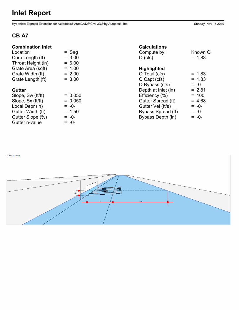
Inlet Report
Hydraflow Express Extension for Autodesk® AutoCAD® Civil 3D® by Autodesk, Inc. Sunday, Nov 17 2019
CB A7
Combination InletLocation = SagCurb Length (ft) = 3.00Throat Height (in) = 6.00Grate Area (sqft) = 1.00Grate Width (ft) = 2.00Grate Length (ft) = 3.00
GutterSlope, Sw (ft/ft) = 0.050Slope, Sx (ft/ft) = 0.050Local Depr (in) = -0-Gutter Width (ft) = 1.50Gutter Slope (%) = -0-Gutter n-value = -0-
CalculationsCompute by: Known QQ (cfs) = 1.83
HighlightedQ Total (cfs) = 1.83Q Capt (cfs) = 1.83Q Bypass (cfs) = -0-Depth at Inlet (in) = 2.81Efficiency (%) = 100Gutter Spread (ft) = 4.68Gutter Vel (ft/s) = -0-Bypass Spread (ft) = -0-Bypass Depth (in) = -0-
Inlet Report
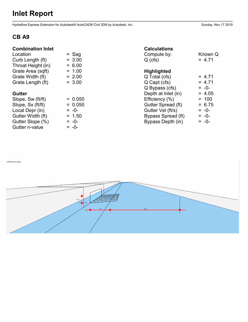
Hydraflow Express Extension for Autodesk® AutoCAD® Civil 3D® by Autodesk, Inc. Sunday, Nov 17 2019
CB A9
Combination InletLocation = SagCurb Length (ft) = 3.00Throat Height (in) = 6.00Grate Area (sqft) = 1.00Grate Width (ft) = 2.00Grate Length (ft) = 3.00
GutterSlope, Sw (ft/ft) = 0.050Slope, Sx (ft/ft) = 0.050Local Depr (in) = -0-Gutter Width (ft) = 1.50Gutter Slope (%) = -0-Gutter n-value = -0-
CalculationsCompute by: Known QQ (cfs) = 4.71
HighlightedQ Total (cfs) = 4.71Q Capt (cfs) = 4.71Q Bypass (cfs) = -0-Depth at Inlet (in) = 4.05Efficiency (%) = 100Gutter Spread (ft) = 6.75Gutter Vel (ft/s) = -0-Bypass Spread (ft) = -0-Bypass Depth (in) = -0-
Inlet Report
Hydraflow Express Extension for Autodesk® AutoCAD® Civil 3D® by Autodesk, Inc. Sunday, Nov 17 2019
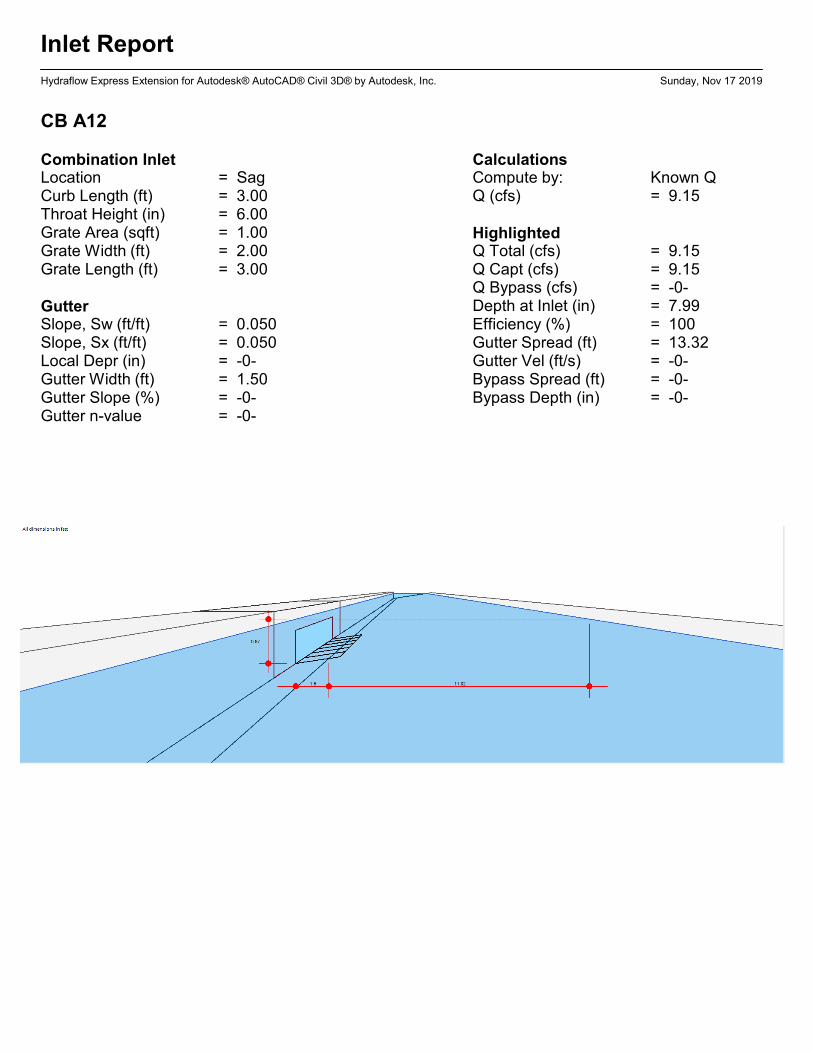
CB A12
Combination InletLocation = SagCurb Length (ft) = 3.00Throat Height (in) = 6.00Grate Area (sqft) = 1.00Grate Width (ft) = 2.00Grate Length (ft) = 3.00
GutterSlope, Sw (ft/ft) = 0.050Slope, Sx (ft/ft) = 0.050Local Depr (in) = -0-Gutter Width (ft) = 1.50Gutter Slope (%) = -0-Gutter n-value = -0-
CalculationsCompute by: Known QQ (cfs) = 9.15
HighlightedQ Total (cfs) = 9.15Q Capt (cfs) = 9.15Q Bypass (cfs) = -0-Depth at Inlet (in) = 7.99Efficiency (%) = 100Gutter Spread (ft) = 13.32Gutter Vel (ft/s) = -0-Bypass Spread (ft) = -0-Bypass Depth (in) = -0-

APPENDIX C – Stormwater Quality Calculations
SECTION [_____]
STORM WATER TREATMENT DEVICE
PART 1 – GENERAL
1.1 DESCRIPTION
A. Scope
The Contractor shall furnish all labor, equipment and materials necessary to install the storm water treatment device(s) (SWTD) and appurtenances specified in the Drawings and these specifications.
B. Related Sections
Section 02240: Dewatering Section 02260: Excavation Support and Protection Section 02315: Excavation and Fill Section 02340: Soil Stabilization
1.2 QUALITY ASSURANCES
A. Inspection
All components shall be subject to inspection by the engineer at the place of manufacture and/or installation. All components are subject to being rejected or identified for repair if the quality of materials and manufacturing do not comply with the requirements of this specification. Components which have been identified as defective may be subject for repair where final acceptance of the component is contingent on the discretion of the Engineer.
B. Warranty
The manufacturer shall guarantee the SWTD components against all manufacturer originated defects in materials or workmanship for a period of twelve (12) months from the date the components are delivered to the owner for installation. The manufacturer shall upon its determination repair, correct or replace any manufacturer originated defects advised in writing to the manufacturer within the referenced warranty period. The use of SWTD components shall be limited to the application for which it was specifically designed.
C. Manufacturer’s Performance Certificate
The SWTD manufacturer shall submit to the Engineer of Record a “Manufacturer’s Performance Certification” certifying that each SWTD is capable of achieving the specified removal efficiencies listed in these specifications. The certification shall be supported by independent third-party research
1.3 SUBMITTALS
A. Shop Drawings
The contractor shall prepare and submit shop drawings in accordance with Section [_____] of the contract documents. The shop drawings shall detail horizontal and vertical dimensioning as well as joint type and locations.
1.4 PRODUCT SUBMITTALS
No product substitutions shall be accepted unless submitted 10 days prior to project bid date, or as directed by the engineer of record. Submissions for substitutions require review and approval by the Engineer of Record, for hydraulic performance, impact to project designs, equivalent treatment performance, and any required project plan and report (hydrology/hydraulic, water quality, stormwater pollution) modifications that would be required by the approving jurisdictions/agencies. Contractor to coordinate with the Engineer of Record any applicable modifications to the project estimates of cost, bonding amount determinations, plan check fees for changes to approved documents, and/or any other regulatory requirements resulting from product substitutions.
PART 2.0 – PRODUCTS
2.1 MATERIALS AND DESIGN
A. Housing unit of stormwater treatment device shall be constructed of pre-cast or cast-in-place concrete, no exceptions. Precast concrete components shall conform to applicable sections of ASTM C 478, ASTM C 857 and ASTM C 858 and the following: 1. Concrete shall achieve a minimum 28-day compressive strength of 4,000
pounds per square-inch (psi); 2. Unless otherwise noted, the precast concrete sections shall be designed to
withstand lateral earth and AASHTO H-20 traffic loads; 3. Cement shall be Type III Portland Cement conforming to ASTM C 150; 4. Aggregates shall conform to ASTM C 33; 5. Reinforcing steel shall be deformed billet-steel bars, welded steel wire or
deformed welded steel wire conforming to ASTM A 615, A 185, or A 497. 6. Joints shall be sealed with preformed joint sealing compound conforming to
ASTM C 990. 7. Shipping of components shall not be initiated until a minimum compressive
strength of 4,000 psi is attained or five (5) calendar days after fabrication has expired, whichever occurs first.
B. Internal Components and appurtenances shall conform to the following:
1. Screen and support structure shall be manufactured of Type 316 and 316L stainless steel conforming to ASTM F 1267-01;
2. Hardware shall be manufactured of Type 316 stainless steel conforming to ASTM A 320;
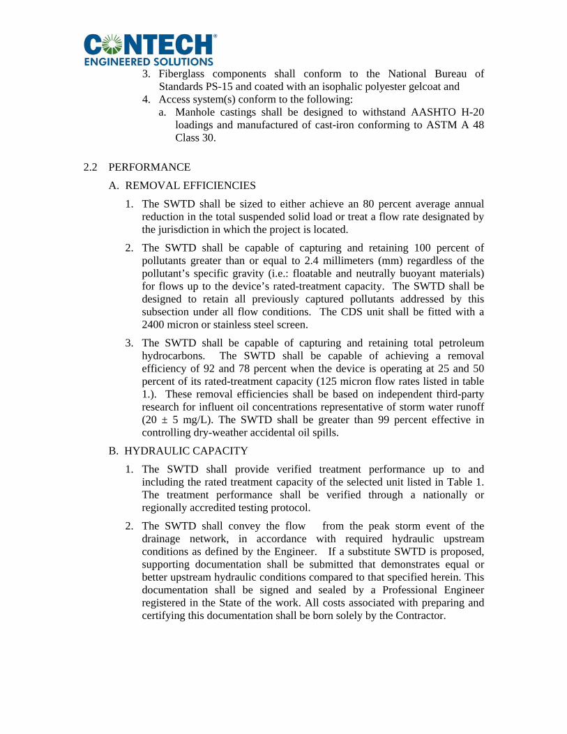
3. Fiberglass components shall conform to the National Bureau of
Standards PS-15 and coated with an isophalic polyester gelcoat and 4. Access system(s) conform to the following:
a. Manhole castings shall be designed to withstand AASHTO H-20 loadings and manufactured of cast-iron conforming to ASTM A 48 Class 30.
2.2 PERFORMANCE
A. REMOVAL EFFICIENCIES
1. The SWTD shall be sized to either achieve an 80 percent average annual reduction in the total suspended solid load or treat a flow rate designated by the jurisdiction in which the project is located.
2. The SWTD shall be capable of capturing and retaining 100 percent of pollutants greater than or equal to 2.4 millimeters (mm) regardless of the pollutant’s specific gravity (i.e.: floatable and neutrally buoyant materials) for flows up to the device’s rated-treatment capacity. The SWTD shall be designed to retain all previously captured pollutants addressed by this subsection under all flow conditions. The CDS unit shall be fitted with a 2400 micron or stainless steel screen.
3. The SWTD shall be capable of capturing and retaining total petroleum hydrocarbons. The SWTD shall be capable of achieving a removal efficiency of 92 and 78 percent when the device is operating at 25 and 50 percent of its rated-treatment capacity (125 micron flow rates listed in table 1.). These removal efficiencies shall be based on independent third-party research for influent oil concentrations representative of storm water runoff (20 ± 5 mg/L). The SWTD shall be greater than 99 percent effective in controlling dry-weather accidental oil spills.
B. HYDRAULIC CAPACITY
1. The SWTD shall provide verified treatment performance up to and including the rated treatment capacity of the selected unit listed in Table 1. The treatment performance shall be verified through a nationally or regionally accredited testing protocol.
2. The SWTD shall convey the flow from the peak storm event of the drainage network, in accordance with required hydraulic upstream conditions as defined by the Engineer. If a substitute SWTD is proposed, supporting documentation shall be submitted that demonstrates equal or better upstream hydraulic conditions compared to that specified herein. This documentation shall be signed and sealed by a Professional Engineer registered in the State of the work. All costs associated with preparing and certifying this documentation shall be born solely by the Contractor.
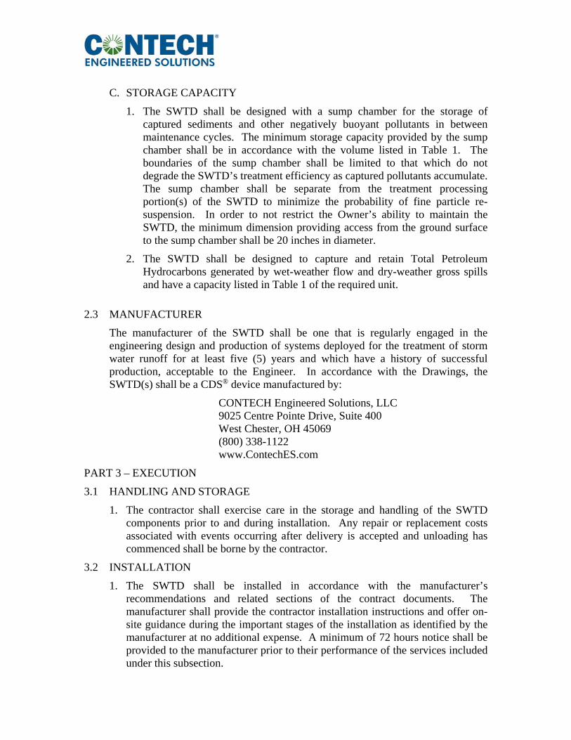
C. STORAGE CAPACITY
1. The SWTD shall be designed with a sump chamber for the storage of captured sediments and other negatively buoyant pollutants in between maintenance cycles. The minimum storage capacity provided by the sump chamber shall be in accordance with the volume listed in Table 1. The boundaries of the sump chamber shall be limited to that which do not degrade the SWTD’s treatment efficiency as captured pollutants accumulate. The sump chamber shall be separate from the treatment processing portion(s) of the SWTD to minimize the probability of fine particle re-suspension. In order to not restrict the Owner’s ability to maintain the SWTD, the minimum dimension providing access from the ground surface to the sump chamber shall be 20 inches in diameter.
2. The SWTD shall be designed to capture and retain Total Petroleum Hydrocarbons generated by wet-weather flow and dry-weather gross spills and have a capacity listed in Table 1 of the required unit.
2.3 MANUFACTURER
The manufacturer of the SWTD shall be one that is regularly engaged in the engineering design and production of systems deployed for the treatment of storm water runoff for at least five (5) years and which have a history of successful production, acceptable to the Engineer. In accordance with the Drawings, the SWTD(s) shall be a CDS® device manufactured by:
CONTECH Engineered Solutions, LLC 9025 Centre Pointe Drive, Suite 400 West Chester, OH 45069 (800) 338-1122 www.ContechES.com
PART 3 – EXECUTION
3.1 HANDLING AND STORAGE
1. The contractor shall exercise care in the storage and handling of the SWTD components prior to and during installation. Any repair or replacement costs associated with events occurring after delivery is accepted and unloading has commenced shall be borne by the contractor.
3.2 INSTALLATION
1. The SWTD shall be installed in accordance with the manufacturer’s recommendations and related sections of the contract documents. The manufacturer shall provide the contractor installation instructions and offer on-site guidance during the important stages of the installation as identified by the manufacturer at no additional expense. A minimum of 72 hours notice shall be provided to the manufacturer prior to their performance of the services included under this subsection.
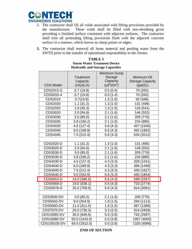
2. The contractor shall fill all voids associated with lifting provisions provided by
the manufacturer. These voids shall be filled with non-shrinking grout providing a finished surface consistent with adjacent surfaces. The contractor shall trim all protruding lifting provisions flush with the adjacent concrete surface in a manner, which leaves no sharp points or edges.
3. The contractor shall removal all loose material and pooling water from the SWTD prior to the transfer of operational responsibility to the Owner.
TABLE 1 Storm Water Treatment Device
Hydraulic and Storage Capacities
CDS Model
Treatment Capacity (cfs)/(L/s)
Minimum Sump Storage Capacity (yd3)/(m3)
Minimum Oil Storage Capacity
(gal)/(L)
CDS2015-G 0.7 (19.8) 0.5 (0.4) 70 (265) CDS2015-4 0.7 (19.8) 0.5 (1.4) 70 (265) CDS2015 0.7(19.8) 1.3 (1.0) 92 (348) CDS2020 1.1 (31.2) 1.3 (1.0) 131 (496) CDS2025 1.6 (45.3) 1.3 (1.0) 143 (541) CDS3020 2.0 (56.6) 2.1 (1.6) 146 (552) CDS3030 3.0 (85.0) 2.1 (1.6) 205 (776) CDS3035 3.8 (106.2) 2.1 (1.6) 234 (885) CDS4030 4.5 (127.4) 5.6 (4.3) 407 (1540) CDS4040 6.0 (169.9) 5.6 (4.3) 492 (1862) CDS4045 7.5 (212.4) 5.6 (4.3) 534 (2012)
CDS2020-D 1.1 (31.2) 1.3 (1.0) 131 (495) CDS3020-D 2.0 (56.6) 2.1 (1.6) 146 (552) CDS3030-D 3.0 (85.0) 2.1 (1.6) 205 (776) CDS3035-D 3.8 (106.2) 2.1 (1.6) 234 (885) CDS4030-D 4.5 (127.4) 4.3 (3.3) 328 (1241) CDS4040-D 6.0 (169.9) 4.3 (3.3) 396 (1499) CDS4045-D 7.5 (212.4) 4.3 (3.3) 430 (1627) CDS5640-D 9.0 (254.9) 5.6 (4.3) 490 (1854) CDS5653-D 14.0 (396.5) 5.6 (4.3) 599 (2267) CDS5668-D 19.0 (538.1) 5.6 (4.3) 733 (2774) CDS5678-D 25.0 (708.0) 5.6 (4.3) 814 (3081)
CDS3030-DV 3.0 (85.0) 2.1 (1.6) 205 (776) CDS5042-DV 9.0 (254.9) 1.9 (1.5) 294 (1112) CDS5050-DV 11.0 (311.5) 1.9 (1.5) 367 (1389) CDS7070-DV 26.0 (736.3) 3.3 (2.5) 914 (3459)
CDS10060-DV 30.0 (849.6) 5.0 (3.8) 792 (2997) CDS10080-DV 50.0 (1416.0) 5.0 (3.8) 1057 (4000)
CDS100100-DV 64.0 (1812.5) 5.0 (3.8) 1320 (4996)
END OF SECTION