drainage design guidelines - shire of nillumbik · · 2015-09-083 design of drainage systems 2...
TRANSCRIPT
G:\Infrastructure_Development\Administration\Policy\DrainageDesignGuidelines\2011DrainageDesignGuidelinesDraft_10052012.doc
Drainage Design Guidelines
Version 1.0
January 2013

G:\Infrastructure_Development\Administration\Policy\DrainageDesignGuidelines\2011DrainageDesignGuidelinesDraft_10052012.doc
TABLE OF CONTENTS
1 OBJECTIVE 1
2 PLANNING REQUIREMENT FOR NEW URBAN AREAS 1
3 DESIGN OF DRAINAGE SYSTEMS 2
3.1 HYDROLOGIC DESIGN 2 3.1.1 Rainfall Data 2 3.1.2 Methods 2 3.1.3 Basis for Calculation 2 3.1.3.1 Catchment 2 3.1.3.2 Runoff Coefficients 2 3.1.3.3 Time of Concentration 3 3.1.3.4 Partial Area Effect 3
3.2 PIPELINE DESIGN 3 3.2.1 Hydraulic Design 3 3.2.2 Design Criteria 4
3.3 PIT DESIGN 6 3.3.1 Hydraulic Design 6 3.3.2 Design Criteria 7
3.4 OVERLAND FLOWS ALONG ROADS / DRIVEWAYS 7 3.4.1 Hydraulic Design 7 3.4.2 Design Criteria 7
3.5 OVERLAND FLOWS IN FLOODWAYS / DRAINAGE RESERVES 8 3.5.1 Hydraulic Design 8 3.5.2 Design Criteria 8
3.6 RURAL DRAINAGE DESIGN 8 3.6.1 Neighborhood Character 8 3.6.2 Open Drains 9 3.6.3 Inlet/Outlet Structures 9
4. DRAWING PRESENTATION 9
4.1 INFORMATION TO BE PROVIDED ON DRAWINGS 9

G:\Infrastructure_Development\Administration\Policy\DrainageDesignGuidelines\2011DrainageDesignGuidelinesDraft_10052012.doc

G:\Infrastructure_Development\Administration\Policy\DrainageDesignGuidelines\2011DrainageDesignGuidelinesDraft_10052012.doc
1 Objective
The objective of the Shire of Nillumbik Drainage Design Guidelines is to provide for the efficient, environmentally sensitive and cost effective control of stormwater runoff and to ensure that a high level of safety and amenity for the public is achieved at all times.
2 Planning requirement for new urban areas
Urban drainage systems within the Shire of Nillumbik must satisfy the
requirements for both the Major / Minor flood predictions.
The Minor System consists of gutter and pipe networks and is typically
designed to pass frequent storm flows (10 year ARI). The Major System consists of overland routes such as roads, drainage reserves, parklands etc., to pass infrequent storm flows (e.g. 100 year ARI). For the design of the Major System, a blockage factor of 50% to the Minor System inlet inflows must be adopted, the pipelines must be assumed as clear. It can be expected that during major storm events there will be floodwaters flowing along streets, drainage reserves and through public open spaces within new subdivisions. T therefore it is essential that during the initial planning stage the following items are considered to determine the most effective use of available land.
Identification of overland flow paths.
Planning for roads, public open space or drainage reserves along overland flow paths.
Consideration of public safety where flooding will impinge upon areas by the public.
Investigate alternative escape routes for situations involving, low points in road, downhill court bowls etc. that could cause flooding to private property.
The control of development within drainage reserves that may cause obstruction to the drainage path of the major storm event (e.g. fences).
This concept also applies to existing urban areas for development of infill subdivisions and site redevelopments which must take into consideration the passage of overland flows for major storm events. This may require developments to be kept clear of overland flow paths, the setting of floor levels above predicted flood levels, the upgrading of existing drains, the provision of drainage easements or reserves for overland flow paths, or other methods that may be required to ensure the passage of major flood events.

2 G:\Infrastructure_Development\Administration\Policy\DrainageDesignGuidelines\2011DrainageDesignGuidelinesDraft_10052012.doc
3 Design of drainage systems
3.1 Hydrologic Design
The Australian Rainfall and Runoff (AR&R) 2001 (or subsequent updates) is to be used as the source for Hydrological Design and base parameters. However this information should be used in conjunction with any other local information that is confirmable, such as flood levels for known storm events and observed flow paths of major flood events. It is the designer’s responsibility to ensure that all calculations are complete and correct and are based on appropriate assumptions.
3.1.1 Rainfall Data
Designs are to be based on the rainfall intensity diagram appropriate for the area. The relative rainfall intensity diagram and tables for the Shire of Nillumbik are attached in Appendix - A (pages 11 to 17).
3.1.2 Methods
The Rational Method must be used as the basis for determining the peak flow rates for the determination of sizes of inlets, pipes and culverts, and overland flow calculations. It is the designer’s responsibility to use the most appropriate method for the situation under investigation.
3.1.3 Basis for Calculation
3.1.3.1 Catchment
The boundaries of the catchment may be determined from contour maps or aerial photographs and/or field inspection. The determination of sub-area catchment boundaries within urban subdivisions requires accurate contour information and a Catchment Plan must be included with the drainage calculations. Where available, plans showing existing drainage networks will be made available by Council. Where the contributing catchment includes existing subdivided areas, the location of existing drainage works needs to be determined and the catchment associated with the drainage network determined. The design must take into account realistic future road patterns where the contributing catchment includes areas subject to future development.
3.1.3.2 Runoff Coefficients
The coefficient of runoff to be used must be determined based upon the fraction of impervious surface within the contributing catchment, and the design recurrence of the storm considered as shown in Appendix-A.

3 G:\Infrastructure_Development\Administration\Policy\DrainageDesignGuidelines\2011DrainageDesignGuidelinesDraft_10052012.doc
3.1.3.3 Time of Concentration
The designer must determine the time of concentration for any sub-catchment by summation of times of travel for overland flow, flow in channels, flow in gutters and pipe flow. The Kinematic Wave Equation may be used to determine the time of overland flow, and as an aid to the designer information has been compiled from the Rainfall data for the Shire of Nillumbik and presented in Appendix-A.
3.1.3.4 Partial Area Effect
The designer is responsible for ensuring that possible “Partial Area Effects” are taken into account when calculating peak flows using the Rational Method.
3.2 Pipeline Design
3.2.1 Hydraulic Design
A full Hydraulic Grade Line (HGL) analysis is required for all designs, and must be carried out by starting at the outfall structure at the lower end of the pipe network, and must proceed upwards through each consecutive pipe run to the most remote structure of pipe network. In the situation where the outfall is into the existing pipe network, the tailwater level must be taken as 150mm below, either the channel invert for SEP or underside pit lid for JP, unless more accurate information is available. Council may require the analysis to continue downstream to confirm the hydraulic assumptions.
Where possible the designer must endeavor to:
Minimise the effect of head losses within the drainage system.
Achieve maximum capacity possible for a given pipe size subject to the economic constraints.
Minimise the risk of sudden overflows from the pipe system.
The methods that can be used to accomplish this are:
Avoid abrupt changes of pipe alignment. Maximum change in alignment of 90 degrees must be achieved.
Where changes of direction is unavoidable the use of splayed pipes is the preferred method for achieving a direction change (applies to pipes over 600mm diameter).
Minimise drops through pits.

4 G:\Infrastructure_Development\Administration\Policy\DrainageDesignGuidelines\2011DrainageDesignGuidelinesDraft_10052012.doc
Where drops through pits are unavoidable the length of pits should be increased to avoid flow impacting the opposite pit wall.
3.2.2 Design Criteria
All Council pipelines must be designed for an ARI of 10 years unless otherwise advised. Floodpaths are to be designed based on 100 year ARI. The rainfall intensity diagram and table to be used are attached in Appendix-A (pages 11 to 17).
The design must take into account contributing catchments of areas subject to future development.
Where pipelines are located within private property and carry runoff other than that contributing by residential properties, the pipeline must be designed for an ARI of 10 years.
All pipes must conform to Councils Standard Specifications and relevant Australian Standards in relation to construction, bedding, cover, splay pipes, etc.
Velocities in pipes must not be less than 0.6 m/s and not greater than 6.0 m/s when the pipe is flowing greater than half full.
Drainage lines within road reserves are to be a minimum of 300mm diameter pipe where under a road pavement and 225mm drain longitudinal to the road.
All pipes draining road runoff must be a minimum 300mm diameter.
All pipes are to be class 2 type as a minimum and class 3 and 4 to be used where structurally required. (Refer to AS 3725 - Loads on Buried Concrete Pipes).
Easement drains must be a minimum 225mm diameter.
Junction pits must have a minimum internal dimension of 600 x 600mm.
All pipelines less than or equal to 450mm diameter must be Rubber Ring Jointed (RRJ) or equivalent.
Anchor blocks are to be used where the pipe grade is steeper than 1 in 10. Refer to Council’s standard drawing or NS1120.

5 G:\Infrastructure_Development\Administration\Policy\DrainageDesignGuidelines\2011DrainageDesignGuidelinesDraft_10052012.doc
Curved pipelines must be used for pipelines greater than or equal to 600mm diameter where the angle of deflection is greater than 10 degrees. Curved pipes of diameter less than 600mm, and on large radius curves, may be used subject to Council approval and compliance with manufacturer’s specifications.
The design HGL must be at least 150mm below the kerb invert for drains within road reserves or 75mm below the underside of pit lids for drains within easements or reserves.
If a final discharge is into an unlined open channel, the velocity of discharge should be kept below 1.5 m/s to minimise scour at the outlet site. An energy dissipation structure must be provided at the outlet.
All connections to open waterways must be angled downstream and drops must not exceed 300mm from pipe invert to the normal receiving tailwater. Consent from the Responsible Authority must be obtained prior to works commencing on-site.
Spacing between pits must not exceed 90 metres.
The minimum cover to pipes must be 450mm for pipes with easements, and 900mm below top of kerb for pipes within road reserves.
Reduction in flow velocity should be avoided where possible to prevent siltation of drains and drops should be provided through pits to generate the additional velocity required. Minimum drop through pits of 50mm.
All stormwater connections from properties are to be connected directly into the underground drainage system.
Localised fill does not contribute to pipe cover.
Newly created allotments must be protected from overland flow of undeveloped upstream blocks to the satisfaction of the Responsible Authority. All stormwater collected in cutoff drains must be directed to the underground drainage system. Silt barriers must be provided while vegetation establishes within the cutoff drain.
Downstream pipe sizes must be equivalent or greater in diameter than any contributing upstream pipe unless approved by Council.
6 G:\Infrastructure_Development\Administration\Policy\DrainageDesignGuidelines\2011DrainageDesignGuidelinesDraft_10052012.doc
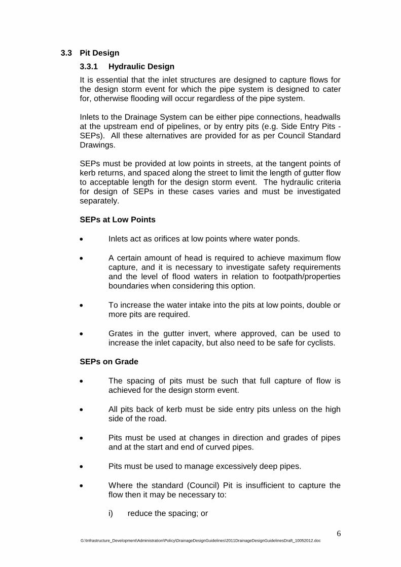
3.3 Pit Design
3.3.1 Hydraulic Design
It is essential that the inlet structures are designed to capture flows for the design storm event for which the pipe system is designed to cater for, otherwise flooding will occur regardless of the pipe system. Inlets to the Drainage System can be either pipe connections, headwalls at the upstream end of pipelines, or by entry pits (e.g. Side Entry Pits - SEPs). All these alternatives are provided for as per Council Standard Drawings. SEPs must be provided at low points in streets, at the tangent points of kerb returns, and spaced along the street to limit the length of gutter flow to acceptable length for the design storm event. The hydraulic criteria for design of SEPs in these cases varies and must be investigated separately.
SEPs at Low Points
Inlets act as orifices at low points where water ponds.
A certain amount of head is required to achieve maximum flow capture, and it is necessary to investigate safety requirements and the level of flood waters in relation to footpath/properties boundaries when considering this option.
To increase the water intake into the pits at low points, double or more pits are required.
Grates in the gutter invert, where approved, can be used to increase the inlet capacity, but also need to be safe for cyclists.
SEPs on Grade
The spacing of pits must be such that full capture of flow is achieved for the design storm event.
All pits back of kerb must be side entry pits unless on the high side of the road.
Pits must be used at changes in direction and grades of pipes and at the start and end of curved pipes.
Pits must be used to manage excessively deep pipes.
Where the standard (Council) Pit is insufficient to capture the flow then it may be necessary to:
i) reduce the spacing; or

7 G:\Infrastructure_Development\Administration\Policy\DrainageDesignGuidelines\2011DrainageDesignGuidelinesDraft_10052012.doc
ii) provide multiple pits (i.e. double or triple).
3.3.2 Design Criteria
All pits located back of kerb must be side entry pits. Pits must be used for all changes of direction for pipes and at start and end of curved pipelines. Side Entry Pits must generally be located at the tangent points of all kerb returns, at all low points of road alignment, and spaced not more than 90 metres. Pits located at the low points of road alignments must be designed to capture design flow assuming a 50% blockage. Head loss factors for pits must be in accordance as per FIG 7.4.13 and FIG 7.4.14 of Vic Roads Road Design Guidelines Part 7-Drainage. Refer appendix-A, pages 11-17.
3.4 Overland Flows Along Roads / Driveways
3.4.1 Hydraulic Design
The Drainage Strategy will permit overland flows along roads for major storm events (e.g. 100 year ARI); however it is the designer’s responsibility to ensure that such flows will not put at risk the safety of pedestrians, the disabled, cyclists or vehicles using the road. The limits in AR&R 1987 (for safety) is for the product of depth and velocity of flow to be less than 0.4m2/s. For new subdivisions or where redevelopment causes the re-direction of major flood waters, the designer must fully comply with the current safety criteria. All submissions must include full details of the magnitude, velocities, and predicted flood levels of overland flows which are likely to occur in a 100 year ARI storm, and what provisions are to be made to safely pass the flood waters within the catchment under consideration.
3.4.2 Design Criteria
The design storm event must be for an ARI of 100 years. The underground drainage system inlets must be considered as 50% blocked for this event (i.e.: blockage is on the inlet not the receiving pipe). For new subdivisions or where redevelopments intentionally re-direct major flood flows along road reserves, then the designer must adopt the current safety standards for suitability of design.

8 G:\Infrastructure_Development\Administration\Policy\DrainageDesignGuidelines\2011DrainageDesignGuidelinesDraft_10052012.doc
The minimum freeboard between the surface level at the boundaries of private properties and the maximum flood level, based upon ARI of 100 years, must be 300mm. Drains downstream of 1 in 100 year drains must also be designed to carry the 1 in 100 year flow to an appropriate surcharge or discharge point as approved by Council.
3.5 Overland Flows In Floodways / Drainage Reserves
3.5.1 Hydraulic Design
The main function of drainage reserves is for the passage and/or storage of flood waters, however they can act as dual purposes (e.g. grazing, pedestrian access etc.), and the secondary use should be consistent with the predicted flood levels and flow velocities to be expected during a major flood event. Floodways therefore need to be designed for the possibility of two sets of criteria, that of channel flow and those criteria associated with street flooding.
3.5.2 Design Criteria
The design storm event must be for an ARI of 100 years.
The exit velocity of pipes discharging to floodways or drainage reserves must be determined and the outlet structure designed to suit.
The minimum freeboard between the surface level at the boundaries of private properties and the maximum flood level, based upon ARI of 100 years, must be 300mm or if not possible use zero freeboard for 100 year ARI and adopt building floor level as 300mm above 100 year ARI.
3.6 Rural Drainage Design
The construction standards for rural roads, where the majority properties are more than 0.4 of a hectare, consist of the road being sealed with open table drains. Drainage service to properties is not provided. Sheet flow off the road pavement is encouraged where possible.
3.6.1 Neighborhood Character
To protect neighbourhood character, subdivisions must be designed to accommodate road and drainage construction without the need to remove native vegetation unless it is absolutely necessary or required for safety reasons.

9 G:\Infrastructure_Development\Administration\Policy\DrainageDesignGuidelines\2011DrainageDesignGuidelinesDraft_10052012.doc
3.6.2 Open Drains
Open drains must be appropriately sized to convey the 1 in 10 year ARI event (in most cases the 1 in 100 year ARI also) and designed to ensure scouring does not occur. The guidelines set in AR&R 2001 Section 1.6.4(v) and/or VicRoads Road Design Guidelines Section 7.6.6.2 must be considered. For steep grades Council may require the introduction of kerb and channel and underground drainage or other methods of treatment to properly manage scouring and the conveyance of stormwater.
3.6.3 Inlet/Outlet Structures
Pit inlets and pipe outlets must be appropriately treated to ensure erosion does not occur.
4. Drawing Presentation
4.1 Information to be provided on Drawings
The following information must be provided on drawings. A sample drawing of a longitudinal section and a pit schedule are shown in Appendix - B (pages 18-22).
Scale plot of HGL on longitudinal elevations of each pipe reach.
HGL levels to AHD.
Flow velocity.
Pipe capacities (running full and design flow).
Pipe diameter, class, and longitudinal grade.
Pipe invert level.
Chainage along centreline of pipe and at all pits.
Natural surface levels and levels of any existing underground services.
Finished surface levels.
Depth to invert below finished surface.
Pit numbers.
Pit schedule.

10 G:\Infrastructure_Development\Administration\Policy\DrainageDesignGuidelines\2011DrainageDesignGuidelinesDraft_10052012.doc
The Pit Schedule is to include:
Pit numbers - pits are to be numbered sequentially with the lowest number at the outlet.
Size.
Type.
Inlet and outlet levels.
Finished top of pit level.
Depth of pit (to outlet).
Pit cover details.

11 G:\Infrastructure_Development\Administration\Policy\DrainageDesignGuidelines\2011DrainageDesignGuidelinesDraft_10052012.doc
APPENDIX A – RAINFALL DATA
RAINFALL DURATION - INTENSITY RELATIONS Rainfall intensity data at three locations within the Shire of Nillumbik were examined. These locations were near Yarrambat, Kangaroo Ground and Strathewen. A comparison in the rainfall intensity values showed an insignificant difference between these locations with intensity values at Strathewen proving to be marginally higher. It was therefore decided that the rainfall intensities near Strathewen be adopted and used throughout the Shire of Nillumbik.

12 G:\Infrastructure_Development\Administration\Policy\DrainageDesignGuidelines\2011DrainageDesignGuidelinesDraft_10052012.doc
DESIGN RAINFALL INTENSITY DIAGRAM Location 37.550 S 145.275 E *near Strathewen Issued 4 January 2011
13 G:\Infrastructure_Development\Administration\Policy\DrainageDesignGuidelines\2011DrainageDesignGuidelinesDraft_10052012.doc
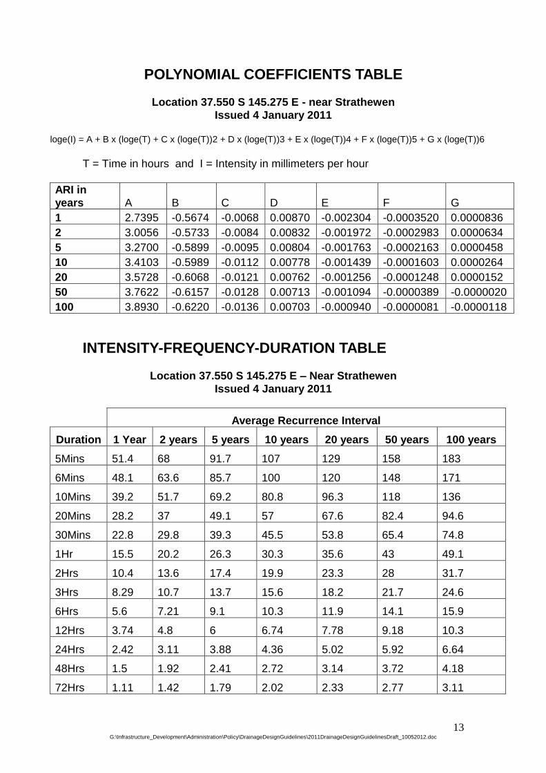
POLYNOMIAL COEFFICIENTS TABLE
Location 37.550 S 145.275 E - near Strathewen
Issued 4 January 2011
loge(I) = A + B x (loge(T) + C x (loge(T))2 + D x (loge(T))3 + E x (loge(T))4 + F x (loge(T))5 + G x (loge(T))6
T = Time in hours and I = Intensity in millimeters per hour
ARI in
years A B C D E F G
1 2.7395 -0.5674 -0.0068 0.00870 -0.002304 -0.0003520 0.0000836
2 3.0056 -0.5733 -0.0084 0.00832 -0.001972 -0.0002983 0.0000634
5 3.2700 -0.5899 -0.0095 0.00804 -0.001763 -0.0002163 0.0000458
10 3.4103 -0.5989 -0.0112 0.00778 -0.001439 -0.0001603 0.0000264
20 3.5728 -0.6068 -0.0121 0.00762 -0.001256 -0.0001248 0.0000152
50 3.7622 -0.6157 -0.0128 0.00713 -0.001094 -0.0000389 -0.0000020
100 3.8930 -0.6220 -0.0136 0.00703 -0.000940 -0.0000081 -0.0000118
INTENSITY-FREQUENCY-DURATION TABLE
Location 37.550 S 145.275 E – Near Strathewen
Issued 4 January 2011
Average Recurrence Interval
Duration 1 Year 2 years 5 years 10 years 20 years 50 years 100 years
5Mins 51.4 68 91.7 107 129 158 183
6Mins 48.1 63.6 85.7 100 120 148 171
10Mins 39.2 51.7 69.2 80.8 96.3 118 136
20Mins 28.2 37 49.1 57 67.6 82.4 94.6
30Mins 22.8 29.8 39.3 45.5 53.8 65.4 74.8
1Hr 15.5 20.2 26.3 30.3 35.6 43 49.1
2Hrs 10.4 13.6 17.4 19.9 23.3 28 31.7
3Hrs 8.29 10.7 13.7 15.6 18.2 21.7 24.6
6Hrs 5.6 7.21 9.1 10.3 11.9 14.1 15.9
12Hrs 3.74 4.8 6 6.74 7.78 9.18 10.3
24Hrs 2.42 3.11 3.88 4.36 5.02 5.92 6.64
48Hrs 1.5 1.92 2.41 2.72 3.14 3.72 4.18
72Hrs 1.11 1.42 1.79 2.02 2.33 2.77 3.11

14 G:\Infrastructure_Development\Administration\Policy\DrainageDesignGuidelines\2011DrainageDesignGuidelinesDraft_10052012.doc
FLOOD ESTIMATION
RAINFALL DURATION – INTENSITY RELATIONS (For up to 3 Days Duration)

15 G:\Infrastructure_Development\Administration\Policy\DrainageDesignGuidelines\2011DrainageDesignGuidelinesDraft_10052012.doc
FLOOD ESTIMATION
RAINFALL DURATION – INTENSITY RELATIONS (For up to 60 Minutes Duration)

16 G:\Infrastructure_Development\Administration\Policy\DrainageDesignGuidelines\2011DrainageDesignGuidelinesDraft_10052012.doc

17 G:\Infrastructure_Development\Administration\Policy\DrainageDesignGuidelines\2011DrainageDesignGuidelinesDraft_10052012.doc

18 G:\Infrastructure_Development\Administration\Policy\DrainageDesignGuidelines\2011DrainageDesignGuidelinesDraft_10052012.doc
APPENDIX B – Hydraulic losses

19 G:\Infrastructure_Development\Administration\Policy\DrainageDesignGuidelines\2011DrainageDesignGuidelinesDraft_10052012.doc

20 G:\Infrastructure_Development\Administration\Policy\DrainageDesignGuidelines\2011DrainageDesignGuidelinesDraft_10052012.doc

21 G:\Infrastructure_Development\Administration\Policy\DrainageDesignGuidelines\2011DrainageDesignGuidelinesDraft_10052012.doc

22 G:\Infrastructure_Development\Administration\Policy\DrainageDesignGuidelines\2011DrainageDesignGuidelinesDraft_10052012.doc