hydro 1000 g - x - unopomp - grundfos - … · example hydro 1000 g cs 3 cr 3-5 3 x 400 v ... the...
TRANSCRIPT

GRUNDFOS DATA BOOKLET
Hydro 1000 G - XGrundfos Hydro 1000 G - X booster sets with 1-4 CR pumps
50 Hz

2
Contents
Product dataPerformance range Page 3Hydro 1000 G - X Page 4Type key Page 4Operating conditions Page 4Other versions on request Page 4Function Page 4Grundfos Control 1000 Page 5Components and materials Page 5Pump Page 6Shaft seal Page 6Motor Page 6Materials CR 3, 5, 10, 15 and 20 Page 7Materials CR 32, 45, 64 and 90 Page 7Materials CRI, CRN Page 7Dimensions and weights Page 7Construction Page 7Installation Page 7
Performance curves/ Technical data/ Electrical dataCR 3 Page 8CR 5 Page 10CR 10 Page 12CR 15 Page 14CR 20 Page 16CR 32 Page 18CR 45 Page 20CR 64 Page 22CR 90 Page 24
Dimensions and weightsBooster set with 1 pump Page 26Booster set with 2 pumps Page 28Booster set with 3 pumps Page 30Booster set with 4 pumps Page 32
Diaphragm tankDiaphragm tank selection Page 34
Further product documentationWinCAPS Page 35WebCAPS Page 36

Product data Hyd
ro 1000 G - XPerformance range
TM0
2 77
82 4
00
3
2 3 4 6 8 10 20 30 40 60 80 100 200 300 400 600
Q [m³/h]
20
30
40
50
60
70
80
90
100
110
[m]H
Hydro 1000 50 Hz
CR 20
CR 15
CR 10
CR 5
CR 3 CR 90
CR 64
CR 45
CR 32
Note: detailed performance curves on pages 8 to 24.
3

4
Product data Hy
dro 1000 G - XHydro 1000 G - XGrundfos Hydro 1000 G - X booster sets consist of 2 to 4 identical Grundfos CR pumps mounted in parallel on a common base frame and a control cabinet with motor protection and integrated CS 1000 controller.
Pumps are automatically operated according to system demand by means of pressure switches (one for each pump). The setting of the pressure switches have to be within the optimal performance area of each pump model.
Hydro 1000 G - X booster sets are supplied as complete, preassembled and tested systems including suction and discharge manifolds, isolating valves, non-return valves, pressure gauge and pressure switches.
A Hydro 1000 G - X booster set with one pump is also available. The booster set is assembled with main mechanical components. However, the control cabinet is simpler and does not incorporate the CS 1000.
To ensure stable operation the booster set must be fitted with a suitable diaphragm tank. The size of the diaphragm tank can be calculated according to the section "Diaphragm tank selection" at page 34.
Fig. 1 Hydro 1000 pressure boosting system
Booster sets without suction manifolds (NOS version) are without these components.
Non-return valves can be fitted on the discharge side on request.
Type key
Operating conditionsFlow: up to 480 m3/h
Operating pressure: max. 10 bar
Liquid temperature: +5°C to +50°C
Ambient temperature: 0°C to +40°C.
Maximum suction lift (H): The maximum suction lift (H) can be calculated as follows:
H = 10.3 - NPSH of the pump - other suction losses - a safety margin of 0.5 metres.
Maximum inlet pressure: 6.0 bar
Power range: up to 30 kW
DOL starting: up to 7.5 kW
SD starting: 11 to 30 kW
Power supply: 3 x 400 V, 50 Hz, N, PE.
Other versions on requestThe following executions are available on request:
• booster set with jokey pump
• booster set without suction manifold (NOS version)
• booster set with CRI, 3, 5, 10, 15, 20 pumps
• all components in contact with water are in high grade stainless steel (N-version)
• performance exceeding the standard range
• characteristics other than stated above
• single-phase power supply: 1 x 230 V, 50 Hz N, PE
• three-phase power supply: 3 x 230 V, 50 Hz N, PE
• starting configuration other than standard
• 60 Hz.
FunctionWhen a tap is opened, water is taken from the diaphragm tank. Then the pressure drops to the first cut-in pressure, and the first pump is cut in.
As the consumption rises, more pumps will be cut in until the performance of the pumps in operation corre-sponds to the requirement.
TM0
0 9
718
250
2VALVE
CS 1000
PRESSURE GAUGE
NON-RETURN
VALVE
ISOLATINGPUMP
PRESSURESWITCH
Hydro 1000
And/or
Example Hydro 1000 G CS 3 CR 3-5 3 x 400 V
Type
G: galvanized manifolds X: stainless steel manifolds
On-off control
Number of pumps
Pump type
Voltage/frequency
Product data Hyd
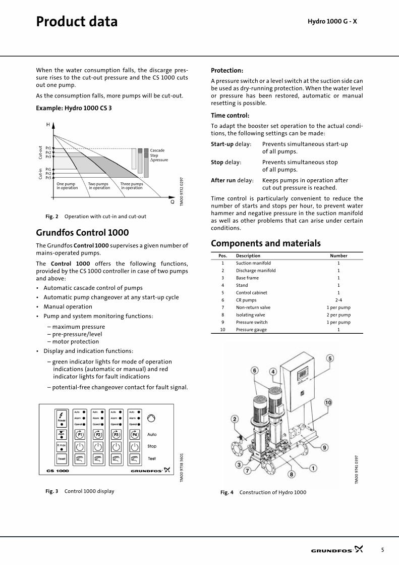
ro 1000 G - XWhen the water consumption falls, the discarge pres-sure rises to the cut-out pressure and the CS 1000 cuts out one pump.
As the consumption falls, more pumps will be cut-out.
Example: Hydro 1000 CS 3
Fig. 2 Operation with cut-in and cut-out
Grundfos Control 1000The Grundfos Control 1000 supervises a given number of mains-operated pumps.
The Control 1000 offers the following functions, provided by the CS 1000 controller in case of two pumps and above:
• Automatic cascade control of pumps
• Automatic pump changeover at any start-up cycle
• Manual operation
• Pump and system monitoring functions:
– maximum pressure – pre-pressure/level – motor protection
• Display and indication functions:
– green indicator lights for mode of operation indications (automatic or manual) and red indicator lights for fault indications
– potential-free changeover contact for fault signal.
Fig. 3 Control 1000 display
Protection:
A pressure switch or a level switch at the suction side can be used as dry-running protection. When the water level or pressure has been restored, automatic or manual resetting is possible.
Time control:
To adapt the booster set operation to the actual condi-tions, the following settings can be made:
Start-up delay: Prevents simultaneous start-up of all pumps.
Stop delay: Prevents simultaneous stop of all pumps.
After run delay: Keeps pumps in operation after cut out pressure is reached.
Time control is particularly convenient to reduce the number of starts and stops per hour, to prevent water hammer and negative pressure in the suction manifold as well as other problems that can arise under certain conditions.
Components and materials
Fig. 4 Construction of Hydro 1000
TM0
0 9
732
029
7TM
00
973
8 36
01
Pr1Pr2Pr3
Pr1Pr2Pr3C
ut-
inC
ut-
out
One pumpin operation
Two pumpsin operation
Three pumpsin operation
CascadeStep∆pressure
Pos. Description Number
1 Suction manifold 1
2 Discharge manifold 1
3 Base frame 1
4 Stand 1
5 Control cabinet 1
6 CR pumps 2-4
7 Non-return valve 1 per pump
8 Isolating valve 2 per pump
9 Pressure switch 1 per pump
10 Pressure gauge 1
TM0
0 9
741
039
7
5

6
Product data Hy
dro 1000 G - XPumpThe CR pump is a non self-priming, vertical multistage centrifugal pump fitted with a Grundfos standard motor.
The pump consists of a base and a pump head. The chamber stack and the outer sleeve are secured between the pump head and the base by means of staybolts. The base has suction and discharge ports on the same level (in-line).
All pumps are equipped with a maintenance-free mechanical shaft seal.
Fig. 5 CR pump
Shaft sealAs standard the CR pump is fitted with either a HQQE shaft seal (Cartridge type).
MotorThe motor is a totally enclosed, fan-cooled, 2-pole Grundfos standard motor with principal dimensions in accordance with the EN/IEC and DIN standards.
Electrical tolerances according to EN 60034/IEC 34.
Electrical data
Motor protection
All motors are protected by the control panel of the booster set.
Three-phase Grundfos motors from 3 kW upwards have a built-in thermistor (PTC) according to DIN 44082.
Single-phase motors have a built-in thermal overload switch.
Advantages and benefits
The state-of-the-art advancements introduced into this new vertical multistage pump generation offer the following benefits:
Enclosure class:Motors: IP 55. Control box: IP 54.
Materials Manifolds:
G = galvanized steel X = AISI 316 Stainless steel (for 2 pumps and above).
Baseframe/stand: Galvanized steel
Isolating valves:Brass (ball type) Cast iron (butterfly type)
Non-return valve:Grundfos type PNV: polypropylene Grundfos type GNV/VMF: cast iron and stainless steel.
Pumps: Grundfos CR type.
GR
7376
Motor
StayboltOuter sleeve
Base
Pump head
Shaft seal Description Max. temp. range [°C]
HQQEO-ring (cartridge) (balanced seal), SiC/SiC, EPDM
–30°C to +120°C
Mounting – up to 4 kW: – from 5.5 kW:
V 18, V 1.
Insulation class: F.
Enclosure class IP 55.
50 Hz Standard voltages
3 x 220-240/380-415 V, for P2 ≤ 3 kW. 3 x 380-415∆ V, for P2 ≥ 4 kW.
High efficency Minimised energy cost
Low NPSH Improves suction capability
Air handling Reduces risks of dry-running
New cartridge concept mechanical seal
Allows to service the pump directly on site without dismantling it from the booster set nor disassembling the liquid end
Spacer couplingAllows to service the mechanical seal without disassembling the motor from the pump (for 11 kW motor onwards)
Sleeve sealingProvices high resistance to pressure pulses and withstands temperature fluctuations as well as external forces
Silicon carbide bearingsWear resistance, improved dry-running capa-bility and handling of thermal shocks enable longer operating time
Reinforced shaft lock ringStrong axial locking force and high torque lock system enable robust and reliable opera-tion of rotating assembly

Product data Hyd
ro 1000 G - XMaterials CR 3, 5, 10, 15 and 20
Materials CR 32, 45, 64 and 90
Materials CRI, CRNThe base, the pump head cover as well as vital pump components of CRI and CRN pumps are made as follows:
Dimensions and weightsDimensions and weights for Hydro 1000 G - X are stated at page 26 to 33.
Please note that the dimensions stated may vary ± 10 mm and that all systems are supplied without vibration dampers. The dimensions may vary following technolog-ical improvements to the components and/or materials used.
ConstructionHydro 1000 G - X is built up on a common base frame. The pumps are fixed to the base frame by means of bolts. The control cabinet is fixed to the base frame by means of a stand.
A suction manifold is mounted on the suction side of the pumps. An isolating valve and non-return valve are mounted between the suction manifold and the indi-vidual pumps. The non-return valve may be mounted on the discharge side at request.
A discharge manifold is mounted on the discharge side of the pumps. An isolating valve is mounted between the discharge manifold and the individual pumps.
InstallationThe Hydro 1000 G - X booster unit has to be installed in a room protected from freezing and that is properly ventilated in order to ensure adequate cooling of the pumps.
The booster must be positioned so as to leave sufficient free room in front and at the sides of it for testing and maintenance and it must be positioned on a flat and even surface, for example on concrete flooring or foun-dation base.
Make sure, in any case, that any possible waterhammers will not have damaging effects on the integrity of the unit.
The pipes connected to the booster must be adequately sized. In order to avoid resonance or mechanical stress due to incorrect alignment, expansion joints must be installed both on the discharge and on the suction mani-fold, if any.
It is always necessary to install supports for the pipes on the discharge and suction sides of the unit, so that the weight of the piping does not come to bear on the mani-folds or on the pumps.
Fig. 6 Mechanical construction
1. Expansion joints 2. Pipe hangers.
Description Materials EN/DIN AISI/ASTM
Pump headCast iron EN-GJL-200
EN-JL1030 ASTM 25B
Shaft Stainless steel 1.4401AISI 316AISI 431
Impeller Stainless steel 1.4301 AISI 304
Chamber Stainless steel 1.4301 AISI 304
Outer sleeve Stainless steel 1.4301 AISI 304
BaseCast iron EN-GJL-200
EN-JL1030 ASTM 25B
Neck ring PTFE
Rubber parts in pump EPDM or FKM
Description Materials EN/DIN AISI/ASTM
Pump headCast iron EN-GJS-500-7
EN-351050ASTM
80-55-06
Motor stoolCast iron EN-GJL-200
EN-JL1030 ASTM 25B
Shaft Stainless steel 1.4057 AISI 431
Impeller Stainless steel 1.4301 AISI 304
Chamber Stainless steel 1.4301 AISI 304
Outer sleeve Stainless steel 1.4301 AISI 304
O-ring for outer sleeve EPDM or FKM
BaseCast iron EN-GJS-500-7
EN-JL1050ASTM
80-55-06
Neck ringCarbon-graphite filled PTFE
Bearing ring Bronze
Bottom bearing ring TC/TC
Rubber parts EPDM or FKM
TC = Tungsten carbide (cemented).
Description Materials EN/DIN AISI/ASTM
CRI
Impeller Stainless steel 1.4301 AISI 304
Chamber Stainless steel 1.4301 AISI 304
Outer sleeve Stainless steel 1.4301 AISI 304
O-ring for outer sleeve EPDM or FKM
CRN
Impeller Stainless steel 1.4401 AISI 316
Chamber Stainless steel 1.4401 AISI 316
Outer sleeve Stainless steel 1.4401 AISI 316
O-ring for outer sleeve EPDM or FKM
All other parts and components are as per the previous tables.
TM0
0 7
748
199
6
2
2
11
2
7

8
Performance curves Hywith 1, 2, 3 or
dro 1000 G - X 4 pumps CR 3
TM0
2 21
19 4
00
3Per
form
ance
cu
rves
/
Tech
nic
al d
ata/
E
lect
rica
l dat
aC
R 3
0 2 4 6 8 10 12 14 16 18 Q [m³/h]
0
10
20
30[m]H
0 1 2 3 4 5 Q [l/s]
0
100
200
300[kPa]
p
CR 3-5
1 2 3 4
0 2 4 6 8 10 12 14 16 18 Q [m³/h]
10
20
30
40[m]H
100
200
300
[kPa]p
CR 3-6
1 2 3 4
0 2 4 6 8 10 12 14 16 18 Q [m³/h]
10
20
30
40[m]H
100
200
300
[kPa]p
CR 3-7
1 2 3 4
0 2 4 6 8 10 12 14 16 18 Q [m³/h]
10
20
30
40
50[m]H
100
200
300
400
[kPa]p
CR 3-8
1 2 3 4
0 2 4 6 8 10 12 14 16 18 Q [m³/h]
20
30
40
50
60[m]H
200
300
400
500
[kPa]p
CR 3-10
1 2 3 4
0 2 4 6 8 10 12 14 16 18 Q [m³/h]
20
30
40
50
60
70[m]H
200
300
400
500
600
[kPa]p
CR 3-12
1 2 3 4
0 2 4 6 8 10 12 14 16 18 Q [m³/h]
30
40
50
60
70
80
90
100[m]H
300
400
500
600
700
800
900
[kPa]p
Hydro 1000CR 3-15
50 HzISO 9906 Annex A
1 2 3 4

Technical data Hydwith 1, 2, 3 or 4
ro 1000 G - X pumps CR 3
Electrical data, flow and settings
No.
of
pu
mp
s
Pump type
Motor Starting Flow [m3/h] Pressure switch settings [bar]
P2[kW]
Imax[A]
DOL Opt. Max.
PR 1 PR 2 PR 3 PR 4
Cut-in Cut-out Cut-in Cut-out Cut-in Cut-out Cut-in Cut-out
1
CR 3-5 0.37 0.98
2.8 4.5
1.2 2.7 - - - - - -
CR 3-6 0.37 0.98 2.0 3.5 - - - - - -
CR 3-7 0.55 1.44 2.5 4.0 - - - - - -
CR 3-8 0.75 1.89 3.0 4.5 - - - - - -
CR 3-10 0.75 1.89 4.3 5.8 - - - - - -
CR 3-12 1.1 2.65 5.5 7.0 - - - - - -
CR 3-15 1.1 2.65 7.3 8.8 - - - - - -
2
CR 3-5 0.37 0.98
5.6 9.0
1.2 2.7 0.9 2.4 - - - -
CR 3-6 0.37 0.98 2.0 3.5 1.7 3.2 - - - -
CR 3-7 0.55 1.44 2.5 4.0 2.2 3.7 - - - -
CR 3-8 0.75 1.89 3.0 4.5 2.7 4.2 - - - -
CR 3-10 0.75 1.89 4.3 5.8 4.0 5.5 - - - -
CR 3-12 1.1 2.65 5.6 7.1 5.3 6.8 - - - -
CR 3-15 1.1 2.65 7.5 9.0 7.2 8.7 - - - -
3
CR 3-5 0.37 0.98
8.4 15.5
1.2 2.7 0.9 2.4 0.6 2.1 - -
CR 3-6 0.37 0.98 2.0 3.5 1.7 3.2 1.4 2.9 - -
CR 3-7 0.55 1.44 2.5 4.0 2.2 3.7 1.9 3.4 - -
CR 3-8 0.75 1.89 3.2 4.7 2.9 4.4 2.6 4.1 - -
CR 3-10 0.75 1.89 4.5 6.0 4.2 5.7 3.9 5.4 - -
CR 3-12 1.1 2.65 5.9 7.4 5.6 7.1 5.3 6.8 - -
CR 3-15 1.1 2.65 7.8 9.3 7.5 9.0 7.2 8.7 - -
4
CR 3-5 0.37 0.98
11.2 18.0
1.2 2.7 0.9 2.4 0.6 2.1 0.3 1.8
CR 3-6 0.37 0.98 2.0 3.5 1.7 3.2 1.4 2.9 1.1 2.6
CR 3-7 0.55 1.44 2.5 4.0 2.2 3.7 1.9 3.4 1.6 3.1
CR 3-8 0.75 1.89 3.2 4.7 2.9 4.4 2.6 4.1 2.3 3.8
CR 3-10 0.75 1.89 4.5 6.0 4.2 5.7 3.9 5.4 3.6 5.1
CR 3-12 1.1 2.65 5.9 7.4 5.6 7.1 5.3 6.8 5.0 6.5
CR 3-15 1.1 2.65 7.8 9.3 7.5 9.0 7.2 8.7 6.9 8.4
DOL: direct on line.
9

10
Performance curves Hywith 1, 2, 3 or
dro 1000 G - X 4 pumps CR 5
TM0
2 21
32 4
00
3CR
50 4 8 12 16 20 24 28 32 Q [m³/h]
0
10
20
30[m]H
0 2 4 6 8 Q [l/s]
0
100
200
300[kPa]
p
CR 5-5
1 2 3 4
0 4 8 12 16 20 24 28 32 Q [m³/h]
10
20
30
40[m]H
100
200
300
[kPa]p
CR 5-7
1 2 3 4
0 4 8 12 16 20 24 28 32 Q [m³/h]
20
30
40
50[m]H
200
300
400
[kPa]p
CR 5-8
1 2 3 4
0 4 8 12 16 20 24 28 32 Q [m³/h]
20
30
40
50
60[m]H
200
300
400
500
[kPa]p
CR 5-9
1 2 3 4
0 4 8 12 16 20 24 28 32 Q [m³/h]
20
30
40
50
60[m]H
200
300
400
500
[kPa]p
CR 5-10
1 2 3 4
0 4 8 12 16 20 24 28 32 Q [m³/h]
30
40
50
60
70
80[m]H
300
400
500
600
700
[kPa]p
CR 5-13
1 2 3 4
0 4 8 12 16 20 24 28 32 Q [m³/h]
40
50
60
70
80
90
100
[m]H
400
500
600
700
800
900
[kPa]p
Hydro 1000CR 5-1550 Hz
ISO 9906 Annex A
1 2 3 4

Technical data Hydwith 1, 2, 3 or 4
ro 1000 G - X pumps CR 5
Electrical data, flow and settings
No.
of
pu
mp
s
Pump type
Motor Starting Flow [m3/h] Pressure switch settings [bar]
P2[kW]
Imax[A]
DOL Opt. Max.
PR 1 PR 2 PR 3 PR 4
Cut-in Cut-out Cut-in Cut-out Cut-in Cut-out Cut-in Cut-out
1
CR 5-5 0.75 1.88
5.5 8.5
1.4 2.9 - - - - - -
CR 5-7 1.1 2.65 2.5 4.0 - - - - - -
CR 5-8 1.1 2.65 3.1 4.6 - - - - - -
CR 5-9 1.5 3.4 4.0 5.5 - - - - - -
CR 5-10 1.5 3.4 4.5 6.0 - - - - - -
CR 5-13 2.2 4.75 6.5 8.0 - - - - - -
CR 5-15 2.2 4.75 7.5 9.0 - - - - - -
2
CR 5-5 0.75 1.88
11.0 17.0
1.4 2.9 1.1 2.6 - - - -
CR 5-7 1.1 2.65 2.7 4.2 2.4 3.9 - - - -
CR 5-8 1.1 2.65 3.3 4.8 3.0 4.5 - - - -
CR 5-9 1.5 3.4 4.2 5.7 3.9 5.4 - - - -
CR 5-10 1.5 3.4 4.8 6.3 4.5 6.0 - - - -
CR 5-13 2.2 4.75 6.8 8.3 6.5 8.0 - - - -
CR 5-15 2.2 4.75 8.2 9.7 7.9 9.4 - - - -
3
CR 5-5 0.75 1.88
16.5 25.5
1.4 2.9 1.1 2.6 0.8 2.3 - -
CR 5-7 1.1 2.65 2.7 4.2 2.4 3.9 2.1 3.6 - -
CR 5-8 1.1 2.65 3.3 4.8 3.0 4.5 2.7 4.2 - -
CR 5-9 1.5 3.4 4.2 5.7 3.9 5.4 3.6 5.1 - -
CR 5-10 1.5 3.4 4.8 6.3 4.5 6.0 4.2 5.7 - -
CR 5-13 2.2 4.75 6.8 8.3 6.5 8.0 6.2 7.7 - -
CR 5-15 2.2 4.75 8.2 9.7 7.9 9.4 7.6 9.1 - -
4
CR 5-5 0.75 1.88
22.0 34.0
1.4 2.9 1.1 2.6 0.8 2.3 0.5 2.0
CR 5-7 1.1 2.65 2.7 4.2 2.4 3.9 2.1 3.6 1.8 3.3
CR 5-8 1.1 2.65 3.3 4.8 3.0 4.5 2.7 4.2 2.4 3.9
CR 5-9 1.5 3.4 4.2 5.7 3.9 5.4 3.6 5.1 3.3 4.8
CR 5-10 1.5 3.4 4.8 6.3 4.5 6.0 4.2 5.7 3.9 5.4
CR 5-13 2.2 4.75 6.8 8.3 6.5 8.0 6.2 7.7 5.9 7.4
CR 5-15 2.2 4.75 8.2 9.7 7.9 9.4 7.6 9.1 7.3 8.8
DOL: direct on line.
11

12
Performance curves Hywith 1, 2, 3 or 4
dro 1000 G - X pumps CR 10
TM0
2 77
79 4
00
3CR
10
0 5 10 15 20 25 30 35 40 45 50 Q [m³/h]
0
10
20
30[m]H
0 2 4 6 8 10 12 14 Q [l/s]
0
100
200
[kPa]p
CR 10-3
1 2 3 4
0 5 10 15 20 25 30 35 40 45 50 Q [m³/h]
10
20
30
40[m]H
100
200
300
[kPa]p
CR 10-4
1 2 3 4
0 5 10 15 20 25 30 35 40 45 50 Q [m³/h]
20
30
40
50[m]H
200
300
400
[kPa]p
CR 10-5
1 2 3 4
0 5 10 15 20 25 30 35 40 45 50 Q [m³/h]
30
40
50
60[m]H
300
400
500
[kPa]p
CR 10-6
1 2 3 4
0 5 10 15 20 25 30 35 40 45 50 Q [m³/h]
40
50
60
70[m]H
400
500
600
[kPa]p
CR 10-7
1 2 3 4
0 5 10 15 20 25 30 35 40 45 50 Q [m³/h]
40
50
60
70
80[m]H
400
500
600
700
[kPa]p
CR 10-8
1 2 3 4
0 5 10 15 20 25 30 35 40 45 50 Q [m³/h]
50
60
70
80
90
100
[m]H
500
600
700
800
900
[kPa]p
Hydro 1000CR 10-10
50 HzISO 9906 Annex A
1 2 3 4
0 5 10 15 20 25 30 35 40 45 50 Q [m³/h]
50
60
70
80
90[m]H
500
600
700
800
[kPa]p
CR 10-9
1 2 3 4

Technical data Hydwith 1, 2, 3 or 4
ro 1000 G - X pumps CR 10
Electrical data, flow and settings
No.
of
pu
mp
s
Pump type
Motor Starting Flow [m3/h] Pressure switch settings [bar]
P2[kW]
Imax[A]
DOL Opt. Max.
PR 1 PR 2 PR 3 PR 4
Cut-in Cut-out Cut-in Cut-out Cut-in Cut-out Cut-in Cut-out
1
CR 10-3 1.1 2.7
10.0 12.0
1.5 2.5 - - - - - -
CR 10-4 1.5 3.4 2.6 3.6 - - - - - -
CR 10-5 2.2 4.8 3.6 4.6 - - - - - -
CR 10-6 2.2 4.8 4.4 5.6 - - - - - -
CR 10-7 3.0 6.3 5.2 6.4 - - - - - -
CR 10-8 3.0 6.3 6.0 7.2 - - - - - -
CR 10-9 3.0 6.3 6.3 7.8 - - - - - -
CR 10-10 4.0 8.0 7.3 8.8 - - - - - -
2
CR 10-3 1.1 2.7
20.0 24.0
1.5 2.5 1.3 2.3 - - - -
CR 10-4 1.5 3.4 2.6 3.6 2.4 3.4 - - - -
CR 10-5 2.2 4.8 3.6 4.6 3.3 4.3 - - - -
CR 10-6 2.2 4.8 4.4 5.6 4.0 5.2 - - - -
CR 10-7 3.0 6.3 5.2 6.4 4.8 6.0 - - - -
CR 10-8 3.0 6.3 6.0 7.2 5.5 6.7 - - - -
CR 10-9 3.0 6.3 6.3 7.8 5.8 7.3 - - - -
CR 10-10 4.0 8.0 7.3 8.8 6.8 8.3 - - - -
3
CR 10-3 1.1 2.7
30.0 36.0
1.5 2.5 1.3 2.3 1.1 2.1 - -
CR 10-4 1.5 3.4 2.6 3.6 2.4 3.4 2.2 3.2 - -
CR 10-5 2.2 4.8 3.6 4.6 3.3 4.3 3.0 4.0 - -
CR 10-6 2.2 4.8 4.4 5.6 4.0 5.2 3.6 4.8 - -
CR 10-7 3.0 6.3 5.2 6.4 4.8 6.0 4.4 5.6 - -
CR 10-8 3.0 6.3 6.0 7.2 5.5 6.7 5.0 6.2 - -
CR 10-9 3.0 6.3 6.3 7.8 5.8 7.3 5.3 6.8 - -
CR 10-10 4.0 8.0 7.3 8.8 6.8 8.3 6.3 7.8 - -
4
CR 10-3 1.1 2.7
40.0 48.0
1.5 2.5 1.3 2.3 1.1 2.1 0.9 1.9
CR 10-4 1.5 3.4 2.6 3.6 2.4 3.4 2.2 3.2 2.0 3.0
CR 10-5 2.2 4.8 3.6 4.6 3.3 4.3 3.0 4.0 2.7 3.7
CR 10-6 2.2 4.8 4.4 5.6 4.0 5.2 3.6 4.8 3.2 4.4
CR 10-7 3.0 6.3 5.2 6.4 4.8 6.0 4.4 5.6 4.0 5.2
CR 10-8 3.0 6.3 6.0 7.2 5.5 6.7 5.0 6.2 4.5 5.7
CR 10-9 3.0 6.3 6.3 7.8 5.8 7.3 5.3 6.8 4.8 6.3
CR 10-10 4.0 8.0 7.3 8.8 6.8 8.3 6.3 7.8 5.8 7.3
Booster sets with these pumps have pressure switches factory set within the operating pressure safety limit.
DOL: direct on line.
Starting configuration other than standard available on request.
13

14
Performance curves Hywith 1, 2, 3 or
dro 1000 G - X 4 pumps CR 15
TM0
2 77
80 4
00
3CR
15
0 10 20 30 40 50 60 70 80 90 Q [m³/h]
0
10
20
30[m]H
0 5 10 15 20 25 Q [l/s]
0
100
200
300[kPa]
p
CR 15-2
1 2 3 4
0 10 20 30 40 50 60 70 80 90 Q [m³/h]
10
20
30
40[m]H
100
200
300
[kPa]p
CR 15-3
1 2 3 4
0 10 20 30 40 50 60 70 80 90 Q [m³/h]
20
30
40
50[m]H
200
300
400
[kPa]p
CR 15-4
1 2 3 4
0 10 20 30 40 50 60 70 80 90 Q [m³/h]
30
40
50
60
70[m]H
300
400
500
600
[kPa]p
CR 15-5
1 2 3 4
0 10 20 30 40 50 60 70 80 90 Q [m³/h]
40
50
60
70
80[m]H
400
500
600
700
[kPa]p
CR 15-6
1 2 3 4
0 10 20 30 40 50 60 70 80 90 Q [m³/h]
50
60
70
80
90
100[m]H
500
600
700
800
900
[kPa]p
CR 15-7
1 2 3 4
0 10 20 30 40 50 60 70 80 90 Q [m³/h]
50
60
70
80
90
100
110
[m]H
500
600
700
800
900
1000
[kPa]p
Hydro 1000CR 15-850 Hz
ISO 9906 Annex A
1 2 3 4

Technical data Hydwith 1, 2, 3 or 4
ro 1000 G - X pumps CR 15
Electrical data, flow and settings
No.
of
pu
mp
s
Pump type
Motor Starting Flow [m3/h] Pressure switch settings [bar]
P2[kW]
Imax[A]
DOL Opt. Max.
PR 1 PR 2 PR 3 PR 4
Cut-in Cut-out Cut-in Cut-out Cut-in Cut-out Cut-in Cut-out
1
CR 15-2 2.2 4.8
22.0 27.0
1.7 2.5 - - - - - -
CR 15-3 3.0 6.3 2.8 3.8 - - - - - -
CR 15-4 4.0 8.0 4.2 5.2 - - - - - -
CR 15-5 4.0 8.0 5.4 6.6 - - - - - -
CR 15-6 5.5 11.0 6.3 7.5 - - - - - -
CR 15-7 5.5 11.0 7.1 8.3 - - - - - -
CR 15-8 7.5 15.2 7.8 9.3 - - - - - -
2
CR 15-2 2.2 4.8
44.0 54.0
1.7 2.5 1.5 2.3 - - - -
CR 15-3 3.0 6.3 2.8 3.8 2.6 3.6 - - - -
CR 15-4 4.0 8.0 4.2 5.2 3.8 4.8 - - - -
CR 15-5 4.0 8.0 5.4 6.6 4.9 6.1 - - - -
CR 15-6 5.5 11.0 6.3 7.5 5.8 7.0 - - - -
CR 15-7 5.5 11.0 7.1 8.3 6.6 7.8 - - - -
CR 15-8 7.5 15.2 7.8 9.3 7.3 8.8 - - - -
3
CR 15-2 2.2 4.8
66.0 81.0
1.7 2.5 1.5 2.3 1.3 2.1 - -
CR 15-3 3.0 6.3 2.8 3.8 2.6 3.6 2.4 3.4 - -
CR 15-4 4.0 8.0 4.2 5.2 3.8 4.8 3.4 4.4 - -
CR 15-5 4.0 8.0 5.4 6.6 4.9 6.1 4.4 5.6 - -
CR 15-6 5.5 11.0 6.3 7.5 5.8 7.0 5.3 6.5 - -
CR 15-7 5.5 11.0 7.1 8.3 6.6 7.8 6.1 7.3 - -
CR 15-8 7.5 15.2 7.8 9.3 7.3 8.8 6.8 8.3 - -
4
CR 15-2 2.2 4.8
88.0 108.0
1.7 2.5 1.5 2.3 1.3 2.1 1.1 1.9
CR 15-3 3.0 6.3 2.8 3.8 2.6 3.6 2.4 3.4 2.2 3.2
CR 15-4 4.0 8.0 4.2 5.2 3.8 4.8 3.4 4.4 3.0 4.0
CR 15-5 4.0 8.0 5.4 6.6 4.9 6.1 4.4 5.6 3.9 5.1
CR 15-6 5.5 11.0 6.3 7.5 5.8 7.0 5.3 6.5 4.8 6.0
CR 15-7 5.5 11.0 7.1 8.3 6.6 7.8 6.1 7.3 5.6 6.8
CR 15-8 7.5 15.2 7.8 9.3 7.3 8.8 6.8 8.3 6.3 7.8
Booster sets with these pumps have pressure switches factory set within the operating pressure safety limit.
DOL: direct on line.
Starting configuration other than standard available on request.
15
16
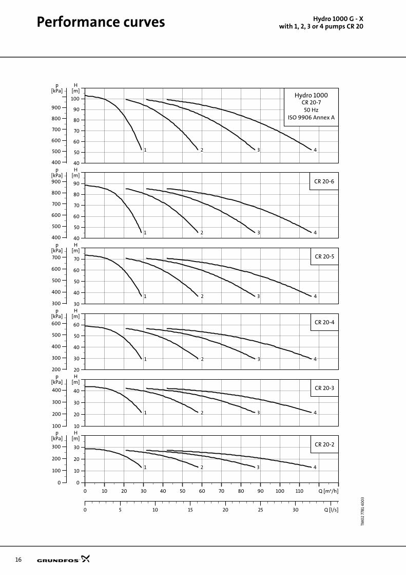
Performance curves Hywith 1, 2, 3 or 4
dro 1000 G - X pumps CR 20
TM0
2 77
81 4
00
3CR
20
0 10 20 30 40 50 60 70 80 90 100 110 Q [m³/h]
0
10
20
30
[m]H
0 5 10 15 20 25 30 Q [l/s]
0
100
200
300
[kPa]p
CR 20-2
1 2 3 4
0 10 20 30 40 50 60 70 80 90 100 110 Q [m³/h]
10
20
30
40
[m]H
100
200
300
400
[kPa]p
CR 20-3
1 2 3 4
0 10 20 30 40 50 60 70 80 90 100 110 Q [m³/h]
20
30
40
50
60
[m]H
200
300
400
500
600[kPa]
p
CR 20-4
1 2 3 4
0 10 20 30 40 50 60 70 80 90 100 110 Q [m³/h]
30
40
50
60
70
[m]H
300
400
500
600
700[kPa]
p
CR 20-5
1 2 3 4
0 10 20 30 40 50 60 70 80 90 100 110 Q [m³/h]
40
50
60
70
80
90
[m]H
400
500
600
700
800
900[kPa]
p
CR 20-6
1 2 3 4
0 10 20 30 40 50 60 70 80 90 100 110 Q [m³/h]
40
50
60
70
80
90
100
[m]H
400
500
600
700
800
900
[kPa]p
Hydro 1000CR 20-750 Hz
ISO 9906 Annex A
1 2 3 4

Technical data Hydwith 1, 2, 3 or 4
ro 1000 G - X pumps CR 20
Electrical data, flow and settings
No.
of
pu
mp
s
Pump type
Motor Starting Flow [m3/h] Pressure switch settings [bar]
P2[kW]
Imax[A]
DOL Opt. Max.
PR 1 PR 2 PR 3 PR 4
Cut-in Cut-out Cut-in Cut-out Cut-in Cut-out Cut-in Cut-out
1
CR 20-2 2.2 4.8
22.0 27.0
1.7 2.5 - - - - - -
CR 20-3 4.0 8.0 2.9 3.9 - - - - - -
CR 20-4 5.5 11.0 4.1 5.3 - - - - - -
CR 20-5 5.5 11.0 5.2 6.4 - - - - - -
CR 20-6 7.5 15.2 6.1 7.3 - - - - - -
CR 20-7 7.5 15.2 6.8 8.3 - - - - - -
2
CR 20-2 2.2 4.8
44.0 54.0
1.7 2.5 1.5 2.3 - - - -
CR 20-3 4.0 8.0 2.9 3.9 2.6 3.6 - - - -
CR 20-4 5.5 11.0 4.1 5.3 3.7 4.9 - - - -
CR 20-5 5.5 11.0 5.2 6.4 4.7 5.9 - - - -
CR 20-6 7.5 15.2 6.1 7.3 5.6 6.8 - - - -
CR 20-7 7.5 15.2 6.8 8.3 6.3 7.8 - - - -
3
CR 20-2 2.2 4.8
66.0 81.0
1.7 2.5 1.5 2.3 1.3 2.1 - -
CR 20-3 4.0 8.0 2.9 3.9 2.6 3.6 2.3 3.3 - -
CR 20-4 5.5 11.0 4.1 5.3 3.7 4.9 3.3 4.5 - -
CR 20-5 5.5 11.0 5.2 6.4 4.7 5.9 4.2 5.4 - -
CR 20-6 7.5 15.2 6.1 7.3 5.6 6.8 5.1 6.3 - -
CR 20-7 7.5 15.2 6.8 8.3 6.3 7.8 5.8 7.3 - -
4
CR 20-2 2.2 4.8
88.0 108.0
1.7 2.5 1.5 2.3 1.3 2.1 1.1 1.9
CR 20-3 4.0 8.0 2.9 3.9 2.6 3.6 2.3 3.3 2.0 3.0
CR 20-4 5.5 11.0 4.1 5.3 3.7 4.9 3.3 4.5 2.9 4.1
CR 20-5 5.5 11.0 5.2 6.4 4.7 5.9 4.2 5.4 3.7 4.9
CR 20-6 7.5 15.2 6.1 7.3 5.6 6.8 5.1 6.3 4.6 5.8
CR 20-7 7.5 15.2 6.8 8.3 6.3 7.8 5.8 7.3 5.3 6.8
Booster sets with these pumps have pressure switches factory set within the operating pressure safety limit.
DOL: direct on line.
Starting configuration other than standard available on request.
17

18
Performance curves Hywith 1, 2, 3 or 4
dro 1000 G - X pumps CR 32
TM0
1 36
10 4
00
3CR
32
0 20 40 60 80 100 120 140 160 Q [m³/h]
0
10
20
30
[m]H
0 10 20 30 40 Q [l/s]
0
100
200
300
[kPa]p
CR 32-2-2
1 2 3 4
0 20 40 60 80 100 120 140 160 Q [m³/h]
10
20
30
40
[m]H
100
200
300
400
[kPa]p
CR 32-2
1 2 3 4
0 20 40 60 80 100 120 140 160 Q [m³/h]
20
30
40
50
60[m]H
200
300
400
500
[kPa]p
CR 32-3
1 2 3 4
0 20 40 60 80 100 120 140 160 Q [m³/h]
30
40
50
60
70
80[m]H
300
400
500
600
700
[kPa]p
CR 32-4
1 2 3 4
0 20 40 60 80 100 120 140 160 Q [m³/h]
50
60
70
80
90
100[m]H
500
600
700
800
900
[kPa]p
CR 32-5
1 2 3 4
0 20 40 60 80 100 120 140 160 Q [m³/h]
50
60
70
80
90
100
110
120
[m]H
500
600
700
800
900
1000
1100
[kPa]p
Hydro 1000CR 32-650 Hz
ISO 9906 Annex A
1 2 3 4
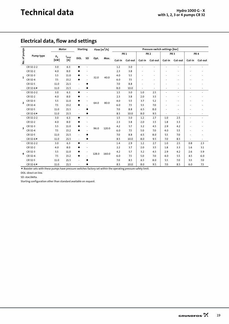
Technical data Hydwith 1, 2, 3 or 4
ro 1000 G - X pumps CR 32
Electrical data, flow and settings
No.
of
pu
mp
s
Pump type
Motor Starting Flow [m3/h] Pressure switch settings [bar]
P2[kW]
Imax[A]
DOL SD Opt. Max.
PR 1 PR 2 PR 3 PR 4
Cut-in Cut-out Cut-in Cut-out Cut-in Cut-out Cut-in Cut-out
1
CR 32-2-2 3.0 6.3 -
32.0 40.0
1.2 3.0 - - - - - -
CR 32-2 4.0 8.0 - 2.3 3.8 - - - - - -
CR 32-3 5.5 11.0 - 4.0 5.5 - - - - - -
CR 32-4 7.5 15.2 - 6.0 7.5 - - - - - -
CR 32-5 11.0 21.5 - 7.0 8.8 - - - - - -
CR 32-6 11.0 21.5 - 8.0 10.0 - - - - - -
2
CR 32-2-2 3.0 6.3 -
64.0 80.0
1.5 3.0 1.0 2.5 - - - -
CR 32-2 4.0 8.0 - 2.3 3.8 2.0 3.5 - - - -
CR 32-3 5.5 11.0 - 4.0 5.5 3.7 5.2 - - - -
CR 32-4 7.5 15.2 - 6.0 7.5 5.5 7.0 - - - -
CR 32-5 11.0 21.5 - 7.0 8.8 6.5 8.0 - - - -
CR 32-6 11.0 21.5 - 8.5 10.0 8.0 9.5 - - - -
3
CR 32-2-2 3.0 6.3 -
96.0 120.0
1.5 3.0 1.2 2.7 1.0 2.5 - -
CR 32-2 4.0 8.0 - 2.3 3.8 2.0 3.5 1.8 3.3 - -
CR 32-3 5.5 11.0 - 4.2 5.7 3.2 4.5 2.9 4.2 - -
CR 32-4 7.5 15.2 - 6.0 7.5 5.0 7.0 4.0 5.5 - -
CR 32-5 11.0 21.5 - 7.0 8.8 6.5 8.0 5.5 7.0 - -
CR 32-6 11.0 21.5 - 8.5 10.0 8.0 9.5 7.0 8.5 - -
4
CR 32-2-2 3.0 6.3 -
128.0 160.0
1.4 2.9 1.2 2.7 1.0 2.5 0.8 2.3
CR 32-2 4.0 8.0 - 2.2 3.7 2.0 3.5 1.8 3.3 1.6 3.1
CR 32-3 5.5 11.0 - 4.2 5.7 3.2 4.5 2.9 4.2 2.6 3.9
CR 32-4 7.5 15.2 - 6.0 7.5 5.0 7.0 4.0 5.5 4.5 6.0
CR 32-5 11.0 21.5 - 7.0 8.5 6.5 8.0 5.5 7.0 5.5 7.0
CR 32-6 11.0 21.5 - 8.5 10.0 8.0 9.5 7.0 8.5 6.0 7.5
Booster sets with these pumps have pressure switches factory set within the operating pressure safety limit.
DOL: direct on line.
SD: star/delta.
Starting configuration other than standard available on request.
19

20
Performance curves Hywith 1, 2, 3 or 4
dro 1000 G - X pumps CR 45
TM0
1 36
11 4
00
3CR
45
0 20 40 60 80 100 120 140 160 180 200 220 Q [m³/h]
0
10
20
30
[m]H
0 10 20 30 40 50 60 Q [l/s]
0
100
200
300
[kPa]p
CR 45-1
1 2 3 4
0 20 40 60 80 100 120 140 160 180 200 220 Q [m³/h]
10
20
30
40
[m]H
100
200
300
400
[kPa]p
CR 45-2-2
1 2 3 4
0 20 40 60 80 100 120 140 160 180 200 220 Q [m³/h]
20
30
40
50
[m]H
200
300
400
500
[kPa]p
CR 45-2
1 2 3 4
0 20 40 60 80 100 120 140 160 180 200 220 Q [m³/h]
30
40
50
60
70
80
[m]H
300
400
500
600
700
800
[kPa]p
CR 45-3
1 2 3 4
0 20 40 60 80 100 120 140 160 180 200 220 Q [m³/h]
50
60
70
80
90
100
[m]H
500
600
700
800
900
1000
[kPa]p
Hydro 1000CR 45-450 Hz
ISO 9906 Annex A
1 2 3 4

Technical data Hydwith 1, 2, 3 or 4
ro 1000 G - X pumps CR 45
Electrical data, flow and settings
No.
of
pu
mp
s
Pump type
Motor Starting Flow [m3/h] Pressure switch settings [bar]
P2[kW]
Imax[A]
DOL SD Opt. Max.
PR 1 PR 2 PR 3 PR 4
Cut-in Cut-out Cut-in Cut-out Cut-in Cut-out Cut-in Cut-out
1
CR 45-1 4.0 8.0 -
45.0 58.0
0.8 2.2 - - - - - -
CR 45-2-2 5.5 11.0 - 2.3 3.8 - - - - - -
CR 45-2 7.5 15.2 - 3.0 4.5 - - - - - -
CR 45-3 11.0 21.5 - 5.8 7.2 - - - - - -
CR 45-4 15.0 28.7 - 8.0 9.5 - - - - - -
2
CR 45-1 4.0 8.0 -
90.0 116.0
0.8 2.2 0.6 2.0 - - - -
CR 45-2-2 5.5 11.0 - 2.3 3.8 1.8 3.3 - - - -
CR 45-2 7.5 15.2 - 3.0 4.5 2.5 4.0 - - - -
CR 45-3 11.0 21.5 - 5.8 7.2 4.5 6.0 - - - -
CR 45-4 15.0 28.7 - 8.0 9.5 7.5 9.0 - - - -
3
CR 45-1 4.0 8.0 -
135.0 174.0
0.8 2.2 0.6 2.0 0.4 1.8 - -
CR 45-2-2 5.5 11.0 - 2.3 3.8 1.8 3.3 1.3 2.8 - -
CR 45-2 7.5 15.2 - 3.0 4.5 2.5 4.0 2.0 3.5 - -
CR 45-3 11.0 21.5 - 5.8 7.2 5.0 6.5 4.5 6.0 - -
CR 45-4 15.0 28.7 - 8.0 9.5 7.5 9.0 7.0 8.5 - -
4
CR 45-1 4.0 8.0 -
180.0 232.0
0.8 2.2 0.7 2.0 0.6 1.8 0.5 1.6
CR 45-2-2 5.5 11.0 - 2.3 3.8 1.8 3.3 1.3 2.8 0.8 2.3
CR 45-2 7.5 15.2 - 3.0 4.5 2.5 4.0 2.0 3.5 1.5 3.0
CR 45-3 11.0 21.5 - 5.8 7.2 5.0 6.5 4.5 6.0 4.0 5.5
CR 45-4 15.0 28.7 - 8.0 9.5 7.5 9.0 7.0 8.5 6.5 8.0
Booster sets with these pumps have pressure switches factory set within the operating pressure safety limit.
DOL: direct on line.
SD: star/delta.
Starting configuration other than standard available on request.
21

22
Performance curves Hywith 1, 2, 3 or 4
dro 1000 G - X pumps CR 64
TM0
1 36
12 4
00
3CR
64
0 40 80 120 160 200 240 280 320 360 Q [m³/h]
10
20
30
40
[m]H
100
200
300
400
[kPa]p
0 20 40 60 80 100 Q [l/s]
CR 64-2-2
1 2 3 4
0 40 80 120 160 200 240 280 320 360 Q [m³/h]
30
40
50
60
[m]H
300
400
500
600
[kPa]p
CR 64-2
1 2 3 4
0 40 80 120 160 200 240 280 320 360 Q [m³/h]
40
50
60
70
80
[m]H
400
500
600
700
800
[kPa]p
CR 64-3-1
1 2 3 4
0 40 80 120 160 200 240 280 320 360 Q [m³/h]
50
60
70
80
90
100
[m]H
500
600
700
800
900
1000
[kPa]p
CR 64-4-2
1 2 3 4
0 40 80 120 160 200 240 280 320 360 Q [m³/h]
60
70
80
90
100
110
120
[m]H
600
700
800
900
1000
1100
1200[kPa]
p
Hydro 1000CR 64-4
50 HzISO 9906 Annex A
1 2 3 4

Technical data Hydwith 1, 2, 3 or 4 p
ro 1000 G - X umps CR 64
Electrical data, flow and settings
No.
of
pu
mp
s
Pump type
Motor Starting Flow [m3/h] Pressure switch settings [bar]
P2[kW]
Imax[A]
DOL SD Opt. Max.
PR 1 PR 2 PR 3 PR 4
Cut-in Cut-out Cut-in Cut-out Cut-in Cut-out Cut-in Cut-out
1
CR 64-2-2 7.5 15.2 -
64.0 85.0
2.2 3.7 - - - - - -
CR 64-2 11.0 21.5 - 3.8 5.2 - - - - - -
CR 64-3-1 15.0 28.7 - 5.3 6.8 - - - - - -
CR 64-4-2 18.5 35.9 - 7.0 8.5 - - - - - -
CR 64-4 22.0 42.0 - 8.0 9.5 - - - - - -
2
CR 64-2-2 7.5 15.2 -
128.0 170.0
2.2 3.7 1.9 3.4 - - - -
CR 64-2 11.0 21.5 - 3.8 5.2 3.3 4.8 - - - -
CR 64-3-1 15.0 28.7 - 5.3 6.8 4.5 6.0 - - - -
CR 64-4-2 18.5 35.9 - 7.0 8.5 6.5 8.0 - - - -
CR 64-4 22.0 42.0 - 8.0 9.5 7.5 9.0 - - - -
3
CR 64-2-2 7.5 15.2 -
192.0 265.0
2.2 3.7 1.9 3.4 1.5 3.0 - -
CR 64-2 11.0 21.5 - 3.8 5.2 3.3 4.8 2.5 4.0 - -
CR 64-3-1 15.0 28.7 - 5.3 6.8 4.5 6.0 4.2 5.5 - -
CR 64-4-2 18.5 35.9 - 7.0 8.5 6.5 8.0 6.0 7.5 - -
CR 64-4 22.0 42.0 - 8.0 9.5 7.5 9.0 7.0 8.5 - -
4
CR 64-2-2 7.5 15.2 -
256.0 350.0
2.2 3.7 1.9 3.4 1.5 3.0 1.0 2.5
CR 64-2 11.0 21.5 - 3.8 5.2 3.3 4.8 2.5 4.0 2.0 3.5
CR 64-3-1 15.0 28.7 - 5.3 6.8 4.5 6.0 4.0 5.5 3.5 5.0
CR 64-4-2 18.5 35.9 - 7.0 8.5 6.5 8.0 6.0 7.5 5.5 7.0
CR 64-4 22.0 42.0 - 8.0 9.5 7.5 9.0 7.0 8.5 6.5 8.0
Booster sets with these pumps have pressure switches factory set within the operating pressure safety limit.
DOL: direct on line.
SD: star/delta.
Starting configuration other than standard available on request.
23

24
Performance curves Hywith 1, 2, 3 or 4
dro 1000 G - X pumps CR 90
TM0
1 36
13 4
00
3CR
90
0 50 100 150 200 250 300 350 400 450 Q [m³/h]
0
10
20
30[m]H
0 20 40 60 80 100 120 140 Q [l/s]
0
100
200
300[kPa]
p
CR 90-1
1 2 3 4
0 50 100 150 200 250 300 350 400 450 Q [m³/h]
0
10
20
30
40[m]H
0
100
200
300
[kPa]p
CR 90-2-2
1 2 3 4
0 50 100 150 200 250 300 350 400 450 Q [m³/h]
20
30
40
50
60[m]H
200
300
400
500
[kPa]p
CR 90-2
1 2 3 4
0 50 100 150 200 250 300 350 400 450 Q [m³/h]
20
30
40
50
60
70
80[m]H
200
300
400
500
600
700
[kPa]p
CR 90-3-2
1 2 3 4
0 50 100 150 200 250 300 350 400 450 500Q [m³/h]
40
50
60
70
80
90
100
110
[m]H
400
500
600
700
800
900
1000
[kPa]p
Hydro 1000CR 90-4-2
50 HzISO 9906 Annex A
1 2 3 4
0 50 100 150 200 250 300 350 400 450 Q [m³/h]
40
50
60
70
80
90
100[m]H
400
500
600
700
800
900
[kPa]p
CR 90-3
1 2 3 4

Technical data Hydwith 1, 2, 3 or 4 p
ro 1000 G - X umps CR 90
Electrical data, flow and settings
No.
of
pu
mp
s
Pump type
Motor Starting Flow [m3/h] Pressure switch settings [bar]
P2[kW]
Imax[A]
DOL SD Opt. Max.
PR 1 PR 2 PR 3 PR 4
Cut-in Cut-out Cut-in Cut-out Cut-in Cut-out Cut-in Cut-out
1
CR 90-1 7.5 15.2 -
90.0 120.0
1.2 2.6 - - - - - -
CR 90-2-2 11.0 21.5 - 3.0 4.5 - - - - - -
CR 90-2 15.0 28.7 - 3.5 5.0 - - - - - -
CR 90-3-2 18.5 35.9 - 4.5 6.0 - - - - - -
CR 90-3 22.0 42.0 - 5.5 7.0 - - - - - -
CR 90-4-2 30.0 56.0 - 7.0 8.5 - - - - - -
2
CR 90-1 7.5 15.2 -
180.0 240.0
1.2 2.6 1.1 2.4 - - - -
CR 90-2-2 11.0 21.5 - 3.0 4.5 2.5 4.0 - - - -
CR 90-2 15.0 28.7 - 3.5 5.0 3.0 4.5 - - - -
CR 90-3-2 18.5 35.9 - 4.5 6.0 4.5 6.0 - - - -
CR 90-3 22.0 42.0 - 5.5 7.0 5.0 6.5 - - - -
CR 90-4-2 30.0 56.0 - 7.0 8.5 6.5 8.0 - - - -
3
CR 90-1 7.5 15.2 -
270.0 360.0
1.2 2.6 1.1 2.4 1.0 2.2 - -
CR 90-2-2 11.0 21.5 - 3.0 4.5 2.5 4.0 2.0 3.5 - -
CR 90-2 15.0 28.7 - 3.5 5.0 3.0 4.5 2.5 4.0 - -
CR 90-3-2 18.5 35.9 - 4.5 6.0 4.5 6.0 4.0 5.5 - -
CR 90-3 22.0 42.0 - 5.5 7.0 5.0 6.5 4.5 6.0 - -
CR 90-4-2 30.0 56.0 - 7.0 8.5 6.5 8.0 6.0 7.5 - -
4
CR 90-1 7.5 15.2 -
360.0 480.0
1.2 2.6 1.1 2.4 1.0 2.2 0.9 2.0
CR 90-2-2 11.0 21.5 - 3.0 4.5 2.5 4.0 2.0 3.5 1.5 3.0
CR 90-2 15.0 28.7 - 3.5 5.0 3.0 4.5 2.5 4.0 2.0 3.5
CR 90-3-2 18.5 35.9 - 4.5 6.0 4.5 6.0 4.0 5.5 3.5 5.0
CR 90-3 22.0 42.0 - 5.5 7.0 5.0 6.5 4.5 6.0 4.0 5.5
CR 90-4-2 30.0 56.0 - 7.0 8.5 6.5 8.0 6.0 7.5 5.5 7.0
Booster sets with these pumps have pressure switches factory set within the operating pressure safety limit.
DOL: direct on line.
SD: star/delta.
Starting configuration other than standard available on request.
25

26
Dimensions and weights
Hydro 1000 G 1 pumpBooster set with 1 pump CR 3 - CR 5 - CR 10
TM0
2 21
31 0
60
2Bo
ost
er s
et w
ith
1 p
um
p
HA
HQ
B2
B
L
Pump typeConnections L
B B2 A HQ HWeight
[kg]G X G X
1 CR 3-5
Rp 1 Rp 1½ 623 700 300 460 90 745
523 35
1 CR 3-6 541 36
1 CR 3-7 559 36
1 CR 3-8 621 38
1 CR 3-10 657 39
1 CR 3-12 693 41
1 CR 3-15 747 43
1 CR 5-5
Rp 1¼ Rp 1¼ 680 700 300 460 90 745
612 38
1 CR 5-7 666 40
1 CR 5-8 693 42
1 CR 5-9 786 43
1 CR 5-10 813 50
1 CR 5-13 894 50
1 CR 5-15 948 63
1 CR 10-3
Rp 1½ Rp 1½ 776 766 300 460 120 745
648 56
1 CR 10-4 744 61
1 CR 10-5 774 61
1 CR 10-6 804 63
1 CR 10-7 893 70
1 CR 10-8 923 71
1 CR 10-9 953 72
1 CR 10-10 1020 85
Note: Dimensions may vary ± 10 mm. Use of vibration dampers influences total height.
G = Galvanised manifolds. X = AISI 316 Stainless steel manifolds.

Dimensions and weights H
ydro 1000 G 1 pumpBooster set with 1 pump CR 15 - CR 20 - CR 32 - CR 45 - CR 64 - CR 90
TM0
2 21
23 3
60
1
B2L
HQ
A
Pump typeConnections
LB2
A HQ HWeight
[kg]G X G X
1 CR 15-2
DN 50 PN 16
DN 50PN 10
720 756 756 150 1455
761 111
1 CR 15-3 860 119
1 CR 15-4 942 133
1 CR 15-5 987 138
1 CR 15-6 1083 157
1 CR 15-7 1128 160
1 CR 15-8DN 50PN 16
1235 175
1 CR 20-2
DN 50 PN 16
DN 50PN 10
720 756 756 150 1455
761 111
1 CR 20-3 897 132
1 CR 20-4 993 157
1 CR 20-5 1038 156
1 CR 20-6 1088 161
1 CR 20-7DN 50PN 16
1128 174
1 CR 32-2-2
DN 65PN 16
DN 65PN 10
900 828 828 165 1455
970 170
1 CR 32-2 1096 193
1 CR 32-3 1096 209
1 CR 32-4 1166 222
1 CR 32-5 1419 261
1 CR 32-6DN 65PN 16
1489 265
1 CR 45-1
DN 80PN 16
DN 80PN 10
900875 875 200 1455
990 185
1 CR 45-2-2 1089 213
1 CR 45-2 1089 220
1 CR 45-3 1352 266
1 CR 45-4 1066 1446 301
1 CR 64-2-2
DN 100PN 16
DN 100PN 10
900
893 893 200 1455
1095 255
1 CR 64-2 1278 309
1 CR 64-3-1
1066
1374 320
1 CR 64-4-2 1457 335
1 CR 64-4DN 100PN 16
1579 343
1 CR 90-1
DN 100PN 16
DN 100PN 10
1066 908 908 200 1455
1022 250
1 CR 90-2-2 1297 298
1 CR 90-2 1311 337
1 CR 90-3-2 1043 352
1 CR 90-3 DN 100PN 16
1525 352
1 CR 90-4-2 1684 490
Note: Dimensions may vary ± 10 mm. Use of vibration dampers influences total height.
G = Galvanised manifolds. X = AISI 316 Stainless steel manifolds.
27

28
Dimensions and weights Hy
dro 1000 G - X 2 pumpsBooster set with 2 pumps CR 3 - CR 5 - CR 10
TM0
2 21
28 3
60
1Bo
ost
er s
et w
ith
2 p
um
ps
B1
L B2
H
A
HQ
Pump typeConnections
LB1 B2
A HQ HWeight
[kg]G X G X G X
2 CR 3-5
G 1½ G 2 600 496 540 544 600 1151160/1500
548 90
2 CR 3-6 566 92
2 CR 3-7 584 92
2 CR 3-8 646 96
2 CR 3-10 682 98
2 CR 3-12 718 102
2 CR 3-15 772 106
2 CR 5-5
G 2 G 2 600 536 568 596 628 1151160/1500
637 94
2 CR 5-7 691 98
2 CR 5-8 718 102
2 CR 5-9 811 104
2 CR 5-10 838 118
2 CR 5-13 919 118
2 CR 5-15 973 124
2 CR 10-3
G 2½ G 2½ 660 640 679 716 752 1451160/1500
673 132
2 CR 10-4 769 142
2 CR 10-5 799 142
2 CR 10-6 829 146
2 CR 10-7 918 160
2 CR 10-8 948 162
2 CR 10-9 978 164
2 CR 10-10 1045 197
Note: Dimensions may vary ± 10 mm. Use of vibration dampers influences total height.
G = Galvanised manifolds. X = AISI 316 Stainless steel manifolds.

Dimensions and weights Hyd
ro 1000 G - X 2 pumpsBooster set with 2 pumps CR 15 - CR 20 - CR 32 - CR 45 - CR 64 - CR 90
Front mounted control cabinet
Side mounted control cabinet
TM0
2 21
24 3
60
1
Front mounted control cabinet
B1LB2
HA
HQ
L2
TM0
2 21
25 3
60
1
Side mounted control cabinet
B1L2B2
H
AH
Q
L
Pump typeConnections
L L2B1 B2
A HQ HWeight
[kg]G X G X G X
2 CR 15-2
DN 80PN 16
DN 80PN 10
720 800 746 746 946 946 1501160/1500
761 191
2 CR 15-3 860 202
2 CR 15-4 942 234
2 CR 15-5 987 244
2 CR 15-6 1083 282
2 CR 15-7 1128 288
2 CR 15-8DN 80PN 16
1235 294
2 CR 20-2
DN 80PN 16
DN 80PN 10
720 800 746 746 946 946 1501160/1500
761 191
2 CR 20-3 897 232
2 CR 20-4 993 282
2 CR 20-5 1038 280
2 CR 20-6 1088 290
2 CR 20-7DN 80PN 16
1128 292
2 CR 32-2-2
DN 100PN 16
DN 100PN 10
900 1000 856 856 1076 1076 1651160/1500
970 329
2 CR 32-2 1096 347
2 CR 32-3 1096 365
2 CR 32-4 1166 381
2 CR 45-1DN 150PN 16
DN 150PN 10
900 1000 1003 948 1288 1233 2001160/1500
990 350
2 CR 45-2-2 1089 368
2 CR 45-2 1089 378
2 CR 64-2-2DN 150PN 16
DN 150PN 10
900 1000 1021 1089 1306 1374 200 1278 448
Pump typeConnections
L L2B1 B2
A HQ HWeight
[kg]G X G X G X
2 CR 32-5 DN 100PN 16
DN 100PN 16
1616 1000 856 856 1076 1076 165 14551419 433
2 CR 32-6 1489 441
2 CR 45-3 DN 150PN 16
DN 150PN 10
1616 1000 1003 948 1288 1233 200 14551352 440
2 CR 45-4 1446 482
2 CR 64-2
DN 150PN 16
DN 150PN 10
1616 1000 1021 1089 1306 1374 200 1455
1278 448
2 CR 64-3-1 1374 524
2 CR 64-4-2 1457 550
2 CR 64-4DN 150PN 16
1579 656
2 CR 90-1
DN 150PN 16
DN 150PN 16
1616 1000 1036 1104 1321 1389 200 1455
1022 380
2 CR 90-2-2 1297 464
2 CR 90-2 1311 530
2 CR 90-3-2 1403 558
2 CR 90-3 DN 150PN 16
1525 664
2 CR 90-4-2 1684 830
Note: Dimensions may vary ± 10 mm. Use of vibration dampers influences total height.
G = Galvanised manifolds. X = AISI 316 Stainless steel manifolds.
29

30
Dimensions and weights Hy
dro 1000 G - X 3 pumpsBooster set with 3 pumps CR 3 - CR 5 - CR 10
TM0
2 21
29 3
60
1Bo
ost
er s
et w
ith
3 p
um
ps
H
B1L2
L B2H
Q
APump type
ConnectionsL L2
B1 B2A HQ H
Weight[kg]G X G X G X
3 CR 3-5
G 1½ G 2 1370 920 496 540 544 600 115 1455
548 123
3 CR 3-6 566 126
3 CR 3-7 584 129
3 CR 3-8 646 132
3 CR 3-10 682 135
3 CR 3-12 718 147
3 CR 3-15 772 147
3 CR 5-5
G 2 G 2 1370 920 536 568 596 628 115 1455
637 123
3 CR 5-7 691 129
3 CR 5-8 718 135
3 CR 5-9 811 138
3 CR 5-10 838 177
3 CR 5-13 919 177
3 CR 5-15 973 181
3 CR 10-3
G 2½ G 2½ 1400 980 640 679 716 752 145 1455
673 195
3 CR 10-4 769 193
3 CR 10-5 793 193
3 CR 10-6 829 201
3 CR 10-7 918 211
3 CR 10-8 948 214
3 CR 10-9 978 217
3 CR 10-10 1045 257
Note: Dimensions may vary ± 10 mm. Use of vibration dampers influences total height.
G = Galvanised manifolds. X = AISI 316 Stainless steel manifolds.

Dimensions and weights Hyd
ro 1000 G - X 3 pumpsBooster set with 3 pumps CR 15 - CR 20 - CR 32 - CR 45 - CR 64 - CR 90
TM0
2 21
26 3
60
1
B1L2B2
H
AH
Q
L
TM0
2 21
84 3
801
B1LB2
H
AH
Q
L2LQ
3 CR 90-4-2
Pump typeConnections
L L2 LQB1 B2
A HQ HWeight
[kg]G X G X G X
3 CR 15-2
DN 100PN 16
DN 100PN 10
1670
1200 - 766 766 986 986 150 1455
761 295
3 CR 15-3 860 307
3 CR 15-4 942 344
3 CR 15-5
1870
987 359
3 CR 15-6 1083 416
3 CR 15-7 1128 425
3 CR 15-8DN 100PN 16
1235 434
3 CR 20-2
DN 100PN 16
DN 100PN 10
1670
1200 - 766 766 986 986 150 1455
761 295
3 CR 20-3 897 341
3 CR 20-4
1870
993 416
3 CR 20-5 1038 413
3 CR 20-6 1088 428
3 CR 20-7DN 100PN 16
1128 431
3 CR 32-2-2
DN 150PN 16
DN 150PN 10
2116 1500 - 956 856 1241 1141 165 1455
970 511
3 CR 32-2 1007 538
3 CR 32-3 1096 565
3 CR 32-4 1166 589
3 CR 32-5 1419 712
3 CR 32-6DN 150PN 16
1429 724
3 CR 45-1
DN 200PN 16
DN 200PN 10
2116 1500 - 1073 1071 1413 1411 200 1455
990 562
3 CR 45-2-2 1089 576
3 CR 45-2 1089 644
3 CR 45-3 1352 713
3 CR 45-4 1446 788
3 CR 64-2-2
DN 200PN 16
DN 200PN 10
2116 1500 - 1091 1089 1431 1429 200 1455
1095 615
3 CR 64-2 1278 724
3 CR 64-3-1 1374 838
3 CR 64-4-2 1457 877
3 CR 64-4DN 200PN 16
1579 1036
3 CR 90-1
DN 200PN 16
DN 200PN 10 2116
1500-
1106 1106 1446 1444 200 1455
1022 616
3 CR 90-2-2 1297 742
3 CR 90-2 1311 841
3 CR 90-3-2 1403 883
3 CR 90-3 DN 200PN 16
1525 883
3 CR 90-4-2 1400 826 1684 1291
Note: Dimensions may vary ± 10 mm. Use of vibration dampers influences total height.
G = Galvanised manifolds. X = AISI 316 Stainless steel manifolds.
31

32
Dimensions and weights Hy
dro 1000 G - X 4 pumpsBooster set with 4 pumps CR 3 - CR 5 - CR 10
TM0
2 21
30 3
60
1Bo
ost
er s
et w
ith
4 p
um
ps
B1L2
L B2
HQ
A
HPump type
ConnectionsL L2
B1 B2A HQ H
Weight[kg]G X G X G X
4 CR 3-5
G 2 G 2½ 1690 1240 508 540 568 616 115 1455
548 164
4 CR 3-6 566 168
4 CR 3-7 584 172
4 CR 3-8 646 176
4 CR 3-10 682 180
4 CR 3-12 718 188
4 CR 3-15 772 196
4 CR 5-5
G 2½ G 2½ 1690 1240 552 568 628 644 115 1455
637 164
4 CR 5-7 691 172
4 CR 5-8 718 180
4 CR 5-9 811 184
4 CR 5-10 838 236
4 CR 5-13 919 236
4 CR 5-15 973 242
4 CR 10-3
DN 80PN 16
DN 80PN 10
1720 1300 632 676 832 876 145 1455
673 260
4 CR 10-4 769 264
4 CR 10-5 799 262
4 CR 10-6 829 268
4 CR 10-7 918 282
4 CR 10-8 948 286
4 CR 10-9 978 290
4 CR 10-10DN 80PN 16
1045 344
Note: Dimensions may vary ± 10 mm. Use of vibration dampers influences total height.
G = Galvanised manifolds. X = AISI 316 Stainless steel manifolds.
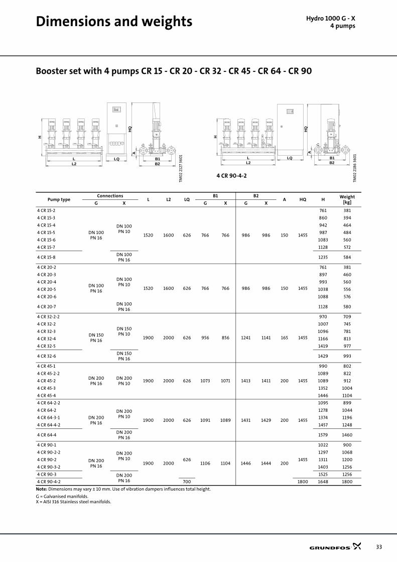
Dimensions and weights Hyd
ro 1000 G - X 4 pumpsBooster set with 4 pumps CR 15 - CR 20 - CR 32 - CR 45 - CR 64 - CR 90
TM0
2 21
27 3
60
1
L
H
B1B2
AH
Q
L2LQ
TM0
2 21
86 3
60
1
L
H
B1B2
AH
Q
L2LQ
4 CR 90-4-2
Pump typeConnections
L L2 LQB1 B2
A HQ HWeight
[kg]G X G X G X
4 CR 15-2
DN 100PN 16
DN 100PN 10
1520 1600 626 766 766 986 986 150 1455
761 381
4 CR 15-3 860 394
4 CR 15-4 942 464
4 CR 15-5 987 484
4 CR 15-6 1083 560
4 CR 15-7 1128 572
4 CR 15-8DN 100PN 16
1235 584
4 CR 20-2
DN 100PN 16
DN 100PN 10
1520 1600 626 766 766 986 986 150 1455
761 381
4 CR 20-3 897 460
4 CR 20-4 993 560
4 CR 20-5 1038 556
4 CR 20-6 1088 576
4 CR 20-7DN 100PN 16
1128 580
4 CR 32-2-2
DN 150PN 16
DN 150PN 10
1900 2000 626 956 856 1241 1141 165 1455
970 709
4 CR 32-2 1007 745
4 CR 32-3 1096 781
4 CR 32-4 1166 813
4 CR 32-5 1419 977
4 CR 32-6DN 150PN 16
1429 993
4 CR 45-1
DN 200PN 16
DN 200PN 10
1900 2000 626 1073 1071 1413 1411 200 1455
990 802
4 CR 45-2-2 1089 822
4 CR 45-2 1089 912
4 CR 45-3 1352 1004
4 CR 45-4 1446 1104
4 CR 64-2-2
DN 200PN 16
DN 200PN 10
1900 2000 626 1091 1089 1431 1429 200 1455
1095 899
4 CR 64-2 1278 1044
4 CR 64-3-1 1374 1196
4 CR 64-4-2 1457 1248
4 CR 64-4DN 200PN 16
1579 1460
4 CR 90-1
DN 200PN 16
DN 200PN 10
1900 2000626
1106 1104 1446 1444 2001455
1022 900
4 CR 90-2-2 1297 1068
4 CR 90-2 1311 1200
4 CR 90-3-2 1403 1256
4 CR 90-3 DN 200PN 16
1525 1256
4 CR 90-4-2 700 1800 1648 1800
Note: Dimensions may vary ± 10 mm. Use of vibration dampers influences total height.
G = Galvanised manifolds. X = AISI 316 Stainless steel manifolds.
33

34
Hydro 1000 G-XDiaphragm tank
Diaphragm tank selectionTo ensure stable operation, the Hydro 1000 G - X booster set must be installed in combination with an adequate diaphragm tank.
The size of the obligatory diaphragm tank can be calcu-lated by means of the followong formula:
V = Tank volume [litres]
Q = Mean flow [m3/h]
∆p = Difference between cut-in and cut-out pressure
Cut-in = Cut-in pressure (lowest) [bar]
nmax = Max. number of starts/stops per hour
k = Constant for diaphragm tank pre-charge pressure: k = 0.9
The diaphragm tank pre-charge pressure is set to 0.9 times the lowest cut-in pressure.
The diaphram tank may also be selected on the basis of the below tables in which the following values have been used:
Motors up to and including 3.0 kW: n = 30 to 100 Motors above 3.0 kW: n = 10 to 30 Diff. between cut-in and cut-out: ∆p = 1.5 [bar]
Grundfos pumps and motors are not subject to any particular limitations as they are tested up to 100 start/stops per hour.
However when dimensioning the diaphragm tank volume the following parameters may also be consid-ered:
• maximum number of start/stops per hour allowed by local regulations
• maximum number of start/stops per hour described by the system designer
• temperature and ventilation conditions
• available space for diaphragm tank installation.
Minimum diaphragm tank volume [litres] at ∆p = 1.5 [bar] and nmax = 30:
Minimum diaphragm tank volume [litres] at ∆p = 1.5 [bar] and nmax = 100:
Refer to the cut-in pressure closest to the lowest setting of the selected booster set.
V Q 1000× 1 cut in–( ) p∆+ +( )×4 nmax p∆××
---------------------------------------------------------------------------------- 1k--×=
Pump typeMinimum diaphragm tank volume [litres]
Cut-in1 [bar]
Cut-in2 [bar]
Cut-in3 [bar]
Cut-in4 [bar]
Cut-in5 [bar]
Cut-in6 [bar]
Cut-in7 [bar]
Cut-in8 [bar]
CR 3 65 84 102 120 140 158 176 195
CR 5 108 135 170 200 232 263 294 324
CR 10 173 222 272 321 370 420 469 518
CR 15 346 444 543 642 741 839 938 1037
CR 20 432 556 679 802 926 1049 1173 1296
CR 32 691 889 1086 1284 1481 1679 1876 2074
CR 45 972 1250 1528 1805 2083 2361 2639 2916
CR 64 1383 1778 2173 2568 2963 3358 3753 4148
CR 90 1944 2500 3055 3611 4166 4722 5277 5833
Pump typeMinimum diaphragm tank volume [litres]
Cut-in1 [bar]
Cut-in2 [bar]
Cut-in3 [bar]
Cut-in4 [bar]
Cut-in5 [bar]
Cut-in6 [bar]
Cut-in7 [bar]
Cut-in8 [bar]
CR 3 20 25 30 36 42 47 53 59
CR 5 33 41 51 60 70 78 88 98
CR 10 52 67 81 96 111 126 141 156
CR 15 104 133 163 193 222 252 281 311
CR 20 130 167 204 241 278 315 352 389
CR 32 207 267 326 385 444 504 563 622
CR 45 292 375 458 542 625 708 792 875
CR 64 415 533 652 770 889 1007 1126 1244
CR 90 583 750 917 1083 1250 1417 1583 1750

ntation
Further product documeIn addition to the printed data booklet, Grundfos offers the following sources of product documentation.
• WinCAPS
• WebCAPS.
WinCAPSWinCAPS is a Windows-based Computer-Aided Product Selection program containing information on more than 90,000 Grundfos products.
Available on CD-ROM in more than 15 languages, WinCAPS offers
• detailed technical information
• selection of the optimum pump solution
• dimensional drawings of each pump
• detailed service documentation
• installation and operating instructions
• wiring diagrams of each pump.
Fig. 7 WinCAPS CD-ROM
Fig. 8 WinCAPS
cd-w
inca
psW
inC
APS
Click on Catalogue andselect a product from theextensive product catalogue.
Click on Sizing and selectthe most suitable pumpfor your application.
35

36
Further product documentation
WebCAPSWebCAPS is a Web-based Computer Aided-Product Selection program and a web-version of WinCAPS.
Available on Grundfos’ homepage, www.grundfos.com, WebCAPS offers
• detailed technical information
• dimensional drawings of each pump
• wiring diagrams of each pump.
Fig. 9 WebCAPS
Web
CA
PS
Click Catalogue andselect a product fromthe extensiveproduct catalogue.
Click Replacementand select the rightreplacement pumpbased on thecurrent installation.
Click Productsearch and selecta product from theextensive productcatalogue.
Click Service toto find informationon service kits andspare parts.
Click Units and select yourpreferred units of measurement:- Default units- SI units- US units.
Click Language andselect your preferredlanguage.
Click Literature toselect and downloadGrundfos documentationby browsing the productranges or performinga specific search. Theliterature includes:- Data booklets- Installation and
- Service instructions.operating instructions
If you are a registereduser click Log in to:- save your settings- define and save your
own units- save personalised
information.

37

38

39

www.grundfos.com
V7127644 0604GBRepl. V7127644 0702 Subject to alterations.
GRUNDFOS A/S . DK-8850 Bjerringbro . Denmark Telephone: +45 87 50 14 00.
Being responsible is our foundationThinking ahead makes it possible
Innovation is the essence