hydraulic clutch - soft drive - immediate stop - engine
TRANSCRIPT
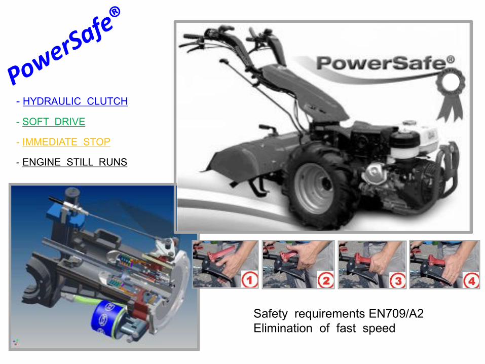
Safety requirements EN709/A2Elimination of fast speed
- HYDRAULIC CLUTCH
- SOFT DRIVE
- IMMEDIATE STOP
- ENGINE STILL RUNS

AMin. 6 max. 9 bar1/8” gas
1 1) Check the pressure in the circuit before disassembly, remove the cap A (1/8” gas) and connect a hydraulic hose with pressure gauge, the clutch is regular if the pressure reaches min. 6 max. 9 bar.

2) Remove and clean the magnetic cap B
B
2

3) WARNING !! For the following operations and for disassemble the PowerSafe clutch, requires a minimal knowledge of the device. Loosening or tightening the screws E without skills or minimal technical knowledge, you could have the deformation of the spring X and inevitable malfunction of the hydraulic distributors and of the clutch. If this happens, need replace the springs!!
D
E
E
To unscrew or tighten, hold steady (!!) the C levers of hydraulic distributors
with a pin or a clamp
3

4) To replace the oil seals of the C levers, remove the retaining rings D and the screws E, remove the cables, levers and change the oil seals F. Be careful, keep locked levers C (during the removing and/or mounting the screws) with a pin P introduced into the hole of the levers or with a clamp as not to damage the inner springs.
D
D
CF
E
4

5) To disassemble the clutch: Remove the screen G (rings, wires, screws and levers as done in 4, disconnect the hose H, drain the oil, remove the filter J (pay attention to the rings ORindicated)
G
5

6) Continuing with the disassembly of the engine: disconnect the electrical cables, gas etc.., unscrew the screws K and remove the engine, the clutch remains on the engine, at this point you can replace the OR ring in the figure.
K
6

7) Unscrew the screw clutch with hex wrench of 7/32” and an extension pipe blocking the pulley to start the engine with a lever L placed in front of the engine between the cracks of the device
7

8) Remove the clutch with the aid of a M lever (without ruining the flange). With shaft dia. 25 mm (1"), should direct the special ring N with the plane down, turning the crankshaft through recoil-start, remove the spark plug if necessary, remove the clutch. At this point you can replace the OR ring.
N
NLOW
8
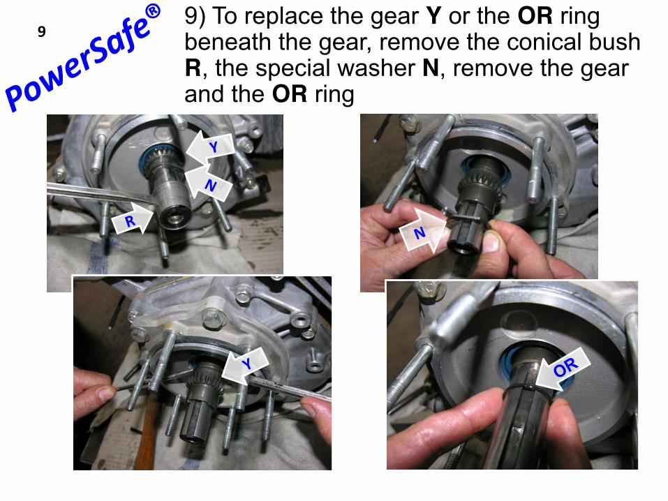
9) To replace the gear Y or the OR ring beneath the gear, remove the conical bush R, the special washer N, remove the gear and the OR ring
9

10) Remove the pressure relief valve S and see if it moves freely, check the spring T and pin U, replace the entire valve S if necessary. IMPORTANT!! Blocking the hydraulic power unit with the grip, we recommend to pay maximum attention in order not to ruin the seals or not to deform the hydraulic power unit.
Where to act with the grip
10

10.1) IMPORTANT!! The PowerSafe device is a multi disk clutch closed by oil in pressure. The pressure depends by the valve of the maximum charge (RELIEF VALVE 2) and by its spring T, it isimpossible to modify or adjust the pressure; the pressure could change between one to another machine, cause of the tollerances machining the parts and, first, by the length of the spring T.
The pressure has to be : 6 ÷ 9 bar, this value is constant, it does not change with the rpm of the engine.If the pressure if less of 5,5 bar the trasmissible couple of the clutch start to decrease. The internal stabilization of the pressure has through the relief valve 2, adjusted by the spring T, discharging the
oil in excess.In standard condition, with the engine to minimum rpm, the flow of the pump is still abundant.The spring T has to have a right measure, 35 mm of lenght; in the picture we see a spring dismounted by a
machine with problem of pressure, the spring was clearly too short.In these conditions, insisting with an implement (as the tiller) with the engine to the minimum rpm, the rpm of the
engine still goes down, decreasing the flow of the pump and the clutch could slip.This shall occurs when the diesel engines have a very high couple at the minimum rpm.The reparation consists to change the spring T with a right sample 35 mm long, following the operations of the
previous table no. 10
10.1

11) Remove the screen V, remove the distributor shafts W (pay attention how the springs X are mounted), recover the springs.
11

12) Remove the pump Z to test the gears A and B, check the gasket C and the pump body. WARNING!! The gear B is screwed in the shaft D with thread pitch left, to unscrew it must act in a clockwise direction as shown in the figure.
WARNING!!thread pitch left
12

1313) Loosen the clutch unit E by the flange without unscrew completely, WARNING !! the thread has a left pitch, to unlock it must act in a clockwise direction as shown, pull out the pin F from its housing with the help of a screwdriver and/or clamp, after removing the pin F unscrew completely the unit E
F
WARNING!!thread pitch left
FLANGE
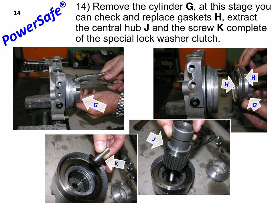
14) Remove the cylinder G, at this stage you can check and replace gaskets H, extract the central hub J and the screw K complete of the special lock washer clutch.
H
14

15) Secure the clutch bell Y in the grip protecting with aluminum shoes, (without deforming ). WARNING!! the thread of the bell Y, has left pitch. Tapping or using a drive-pin in all side holes, unscrew the M ring clockwise, unlock and remove the ring, bearing N, slip discs and springs P, pay attention to the sense of the convex springs for the phase of replacement.
WARNING!!thread pitch left
15

16) Remove the bearing R with discs support S, the clutch is now completely disassembled, replace the need.
16

17) after step 16, reassembling the clutch is importantto center the springs and the disks using the hub J and the screw with special washer K, then screw the ring Mand tight, then do the opposite operations of how described in the earlier stages up to phase 13, then lock the clutch device as shown in step 18.
17
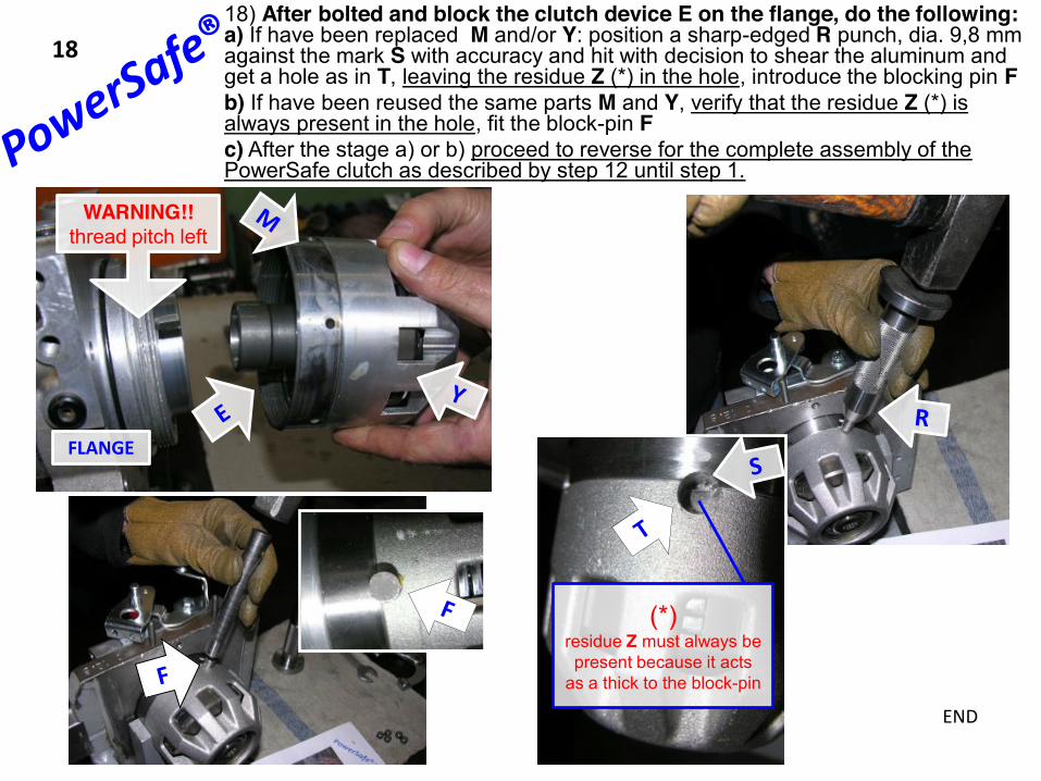
18) After bolted and block the clutch device E on the flange, do the following:a) If have been replaced M and/or Y: position a sharp-edged R punch, dia. 9,8 mm against the mark S with accuracy and hit with decision to shear the aluminum and get a hole as in T, leaving the residue Z (*) in the hole, introduce the blocking pin Fb) If have been reused the same parts M and Y, verify that the residue Z (*) is always present in the hole, fit the block-pin Fc) After the stage a) or b) proceed to reverse for the complete assembly of the PowerSafe clutch as described by step 12 until step 1.
18
WARNING!!thread pitch left
(*) residue Z must always be present because it acts
as a thick to the block-pin
FLANGE
END