the 7-speed dual clutch transmission 0gc · the 7-speed dual clutch transmission has one...
TRANSCRIPT
Self Study Program 850183The 7-speed Dual Clutch Transmission 0GCDesign and Function - Tablet Format, Version 1.1
Volkswagen Group of America, LLC Volkswagen Academy Printed in U.S.A. Printed 5/2018
Course Number SSP 850183, Version 1.1
©2018 Volkswagen Group of America, LLC.
All rights reserved. All information contained in this manual is based on the latest information available at the time of printing and is subject to the copyright and other intellectual property rights of Volkswagen Group of America, LLC., its affiliated companies and its licensors. All rights are reserved to make changes at any time without notice. No part of this document may be reproduced, stored in a retrieval system, or transmitted in any form or by any means, electronic, mechanical, photocopying, recording or otherwise, nor may these materials be modified or reposted to other sites without the prior expressed written permission of the publisher.
All requests for permission to copy and redistribute information should be referred to Volkswagen Group of America, LLC.
Always check Technical Bulletins and the latest electronic repair information for information that may supersede any information included in this booklet.
Trademarks: All brand names and product names used in this manual are trade names, service marks, trademarks, or registered trademarks; and are the property of their respective owners.
Introduction . . . . . . . . . . . . . . . . . . . . . . . . . . . . . . . . . . . . . . . . . . . . . . . . . . . . . . . . . . . . . . . . 1
Transmission Design . . . . . . . . . . . . . . . . . . . . . . . . . . . . . . . . . . . . . . . . . . . . . . . . . . . . . . . . . 4
Oil Circuit . . . . . . . . . . . . . . . . . . . . . . . . . . . . . . . . . . . . . . . . . . . . . . . . . . . . . . . . . . . . . . . . . . . 6
Mechatronic Unit . . . . . . . . . . . . . . . . . . . . . . . . . . . . . . . . . . . . . . . . . . . . . . . . . . . . . . . . . . . 17
Service . . . . . . . . . . . . . . . . . . . . . . . . . . . . . . . . . . . . . . . . . . . . . . . . . . . . . . . . . . . . . . . . . . . . 25
Knowledge Check . . . . . . . . . . . . . . . . . . . . . . . . . . . . . . . . . . . . . . . . . . . . . . . . . . . . . . . . . . 26
Table of Contents
1
Introduction
s556_077
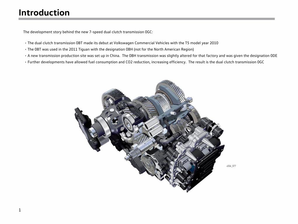
The development story behind the new 7-speed dual clutch transmission 0GC:
• The dual clutch transmission 0BT made its debut at Volkswagen Commercial Vehicles with the T5 model year 2010
• The 0BT was used in the 2011 Tiguan with the designation 0BH (not for the North American Region)
• A new transmission production site was set up in China. The 0BH transmission was slightly altered for that factory and was given the designation 0DE
• Further developments have allowed fuel consumption and CO2 reduction, increasing efficiency. The result is the dual clutch transmission 0GC
2
Introduction
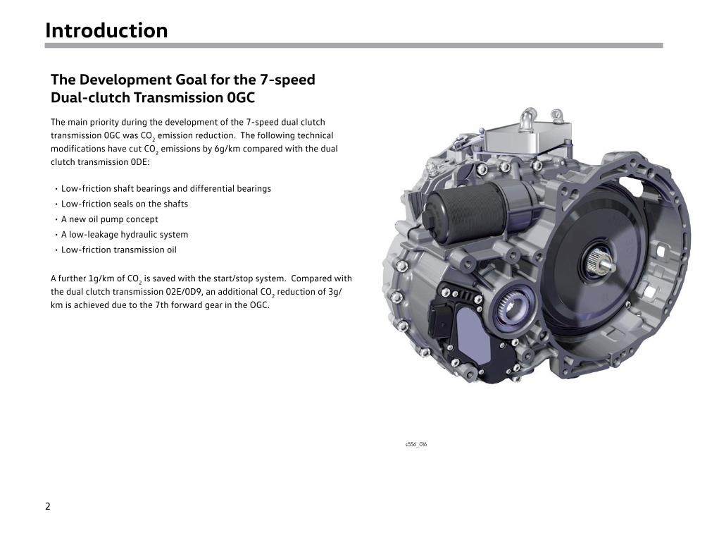
The Development Goal for the 7-speed Dual-clutch Transmission 0GCThe main priority during the development of the 7-speed dual clutch transmission 0GC was CO2 emission reduction. The following technical modifications have cut CO2 emissions by 6g/km compared with the dual clutch transmission 0DE:
• Low-friction shaft bearings and differential bearings
• Low-friction seals on the shafts
• A new oil pump concept
• A low-leakage hydraulic system
• Low-friction transmission oil
A further 1g/km of CO2 is saved with the start/stop system. Compared with the dual clutch transmission 02E/0D9, an additional CO2 reduction of 3g/km is achieved due to the 7th forward gear in the OGC.
s556_016
3
Introduction
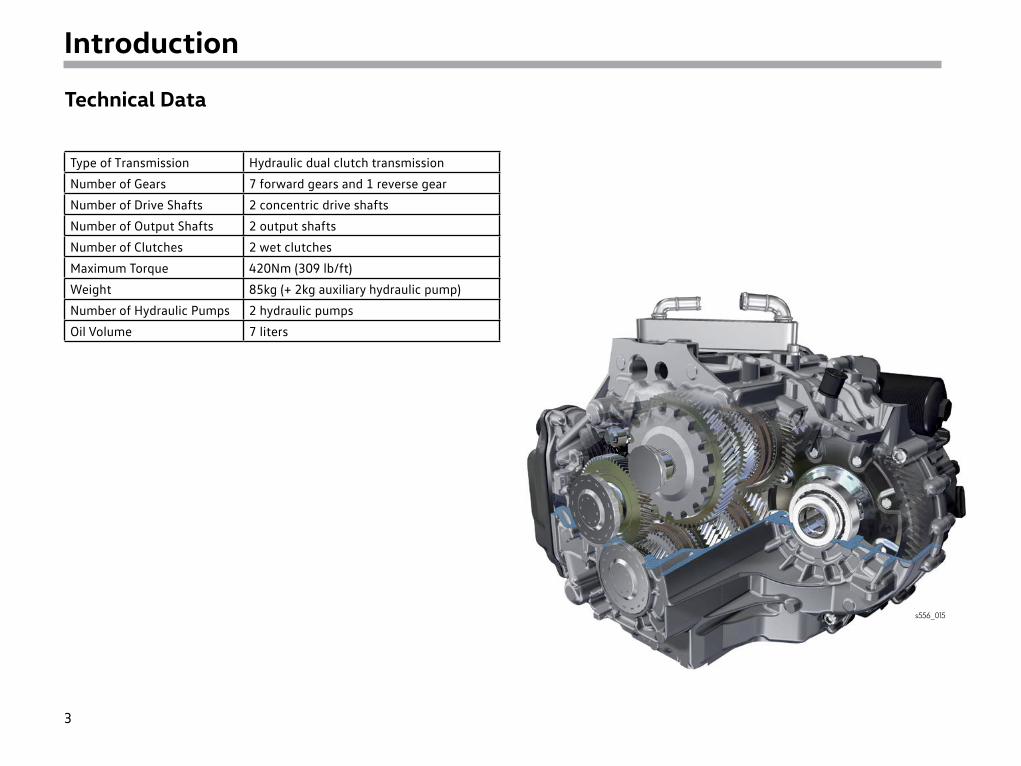
Technical Data
Type of Transmission Hydraulic dual clutch transmission
Number of Gears 7 forward gears and 1 reverse gear
Number of Drive Shafts 2 concentric drive shafts
Number of Output Shafts 2 output shafts
Number of Clutches 2 wet clutches
Maximum Torque 420Nm (309 lb/ft)
Weight 85kg (+ 2kg auxiliary hydraulic pump)
Number of Hydraulic Pumps 2 hydraulic pumps
Oil Volume 7 liters
s556_015
4
Transmission Design
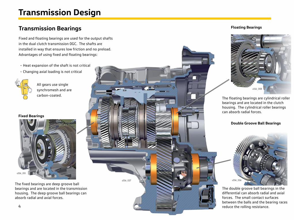
Transmission BearingsFixed and floating bearings are used for the output shafts in the dual clutch transmission 0GC. The shafts are installed in way that ensures low friction and no preload. Advantages of using fixed and floating bearings:
• Heat expansion of the shaft is not critical
• Changing axial loading is not critical
Fixed Bearings
s556_010
The fixed bearings are deep groove ball bearings and are located in the transmission housing. The deep groove ball bearings can absorb radial and axial forces.
The floating bearings are cylindrical roller bearings and are located in the clutch housing. The cylindrical roller bearings can absorb radial forces.
The double groove ball bearings in the differential can absorb radial and axial forces. The small contact surfaces between the balls and the bearing races reduce the rolling resistance.
Double Groove Ball Bearings
Floating Bearings
s556_008
s556_036s556_037
All gears use single synchromesh and are carbon-coated.
5
Transmission Design
s556_070
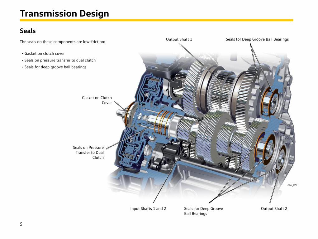
SealsThe seals on these components are low-friction:
• Gasket on clutch cover
• Seals on pressure transfer to dual clutch
• Seals for deep groove ball bearings
Output Shaft 1 Seals for Deep Groove Ball Bearings
Seals on PressureTransfer to Dual
Clutch
Gasket on ClutchCover
Input Shafts 1 and 2 Output Shaft 2Seals for Deep Groove Ball Bearings
6
Oil Circuit
Oil Management
Oil Levels
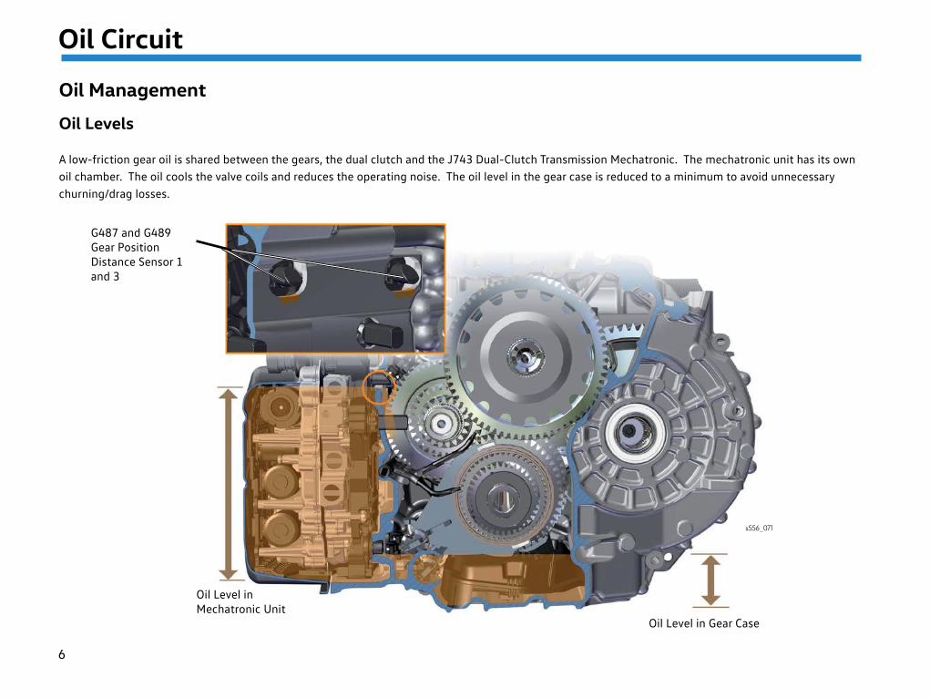
A low-friction gear oil is shared between the gears, the dual clutch and the J743 Dual-Clutch Transmission Mechatronic. The mechatronic unit has its own oil chamber. The oil cools the valve coils and reduces the operating noise. The oil level in the gear case is reduced to a minimum to avoid unnecessary churning/drag losses.
Oil Level in Gear Case
G487 and G489 Gear Position Distance Sensor 1 and 3
Oil Level inMechatronic Unit
s556_071
7
Oil Circuit
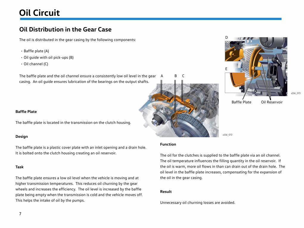
Oil Distribution in the Gear CaseThe oil is distributed in the gear casing by the following components:
• Baffle plate (A)
• Oil guide with oil pick-ups (B)
• Oil channel (C)
The baffle plate and the oil channel ensure a consistently low oil level in the gear casing. An oil guide ensures lubrication of the bearings on the output shafts.
Baffle Plate
The baffle plate is located in the transmission on the clutch housing.
Design
The baffle plate is a plastic cover plate with an inlet opening and a drain hole. It is bolted onto the clutch housing creating an oil reservoir.
Task
The baffle plate ensures a low oil level when the vehicle is moving and at higher transmission temperatures. This reduces oil churning by the gear wheels and increases the efficiency. The oil level is increased by the baffle plate being empty when the transmission is cold and the vehicle moves off. This helps the intake of oil by the pumps.
Function
The oil for the clutches is supplied to the baffle plate via an oil channel. The oil temperature influences the filling quantity in the oil reservoir. If the oil is warm, more oil flows in than can drain out of the drain hole. The oil level in the baffle plate increases, compensating for the expansion of the oil in the gear casing.
Result
Unnecessary oil churning losses are avoided.
Oil ReservoirBaffle Plate
B CA
D
E
s556_072
s556_073
8
Oil Circuit
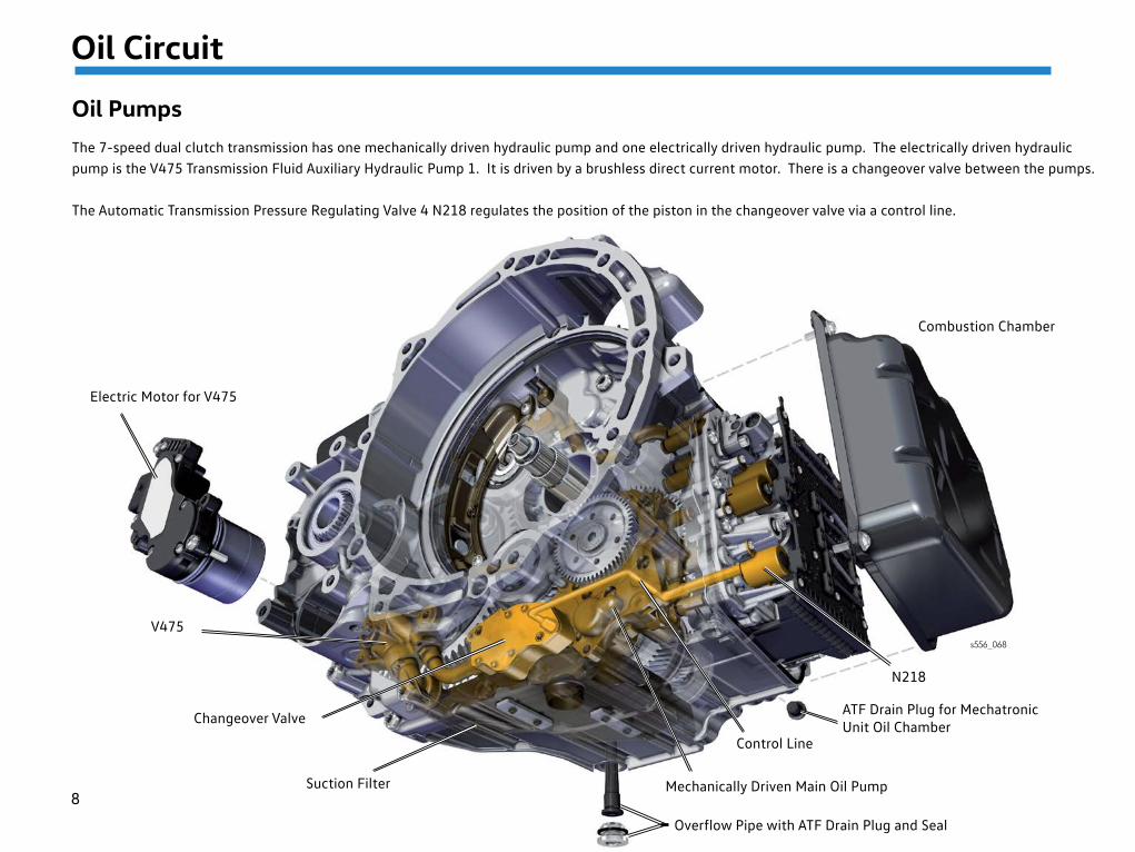
Oil PumpsThe 7-speed dual clutch transmission has one mechanically driven hydraulic pump and one electrically driven hydraulic pump. The electrically driven hydraulic pump is the V475 Transmission Fluid Auxiliary Hydraulic Pump 1. It is driven by a brushless direct current motor. There is a changeover valve between the pumps.
The Automatic Transmission Pressure Regulating Valve 4 N218 regulates the position of the piston in the changeover valve via a control line.
Combustion Chamber
s556_068
Overflow Pipe with ATF Drain Plug and Seal
Mechanically Driven Main Oil Pump
Control Line
ATF Drain Plug for Mechatronic Unit Oil Chamber
N218
Electric Motor for V475
V475
Suction Filter
Changeover Valve
9
Oil Circuit
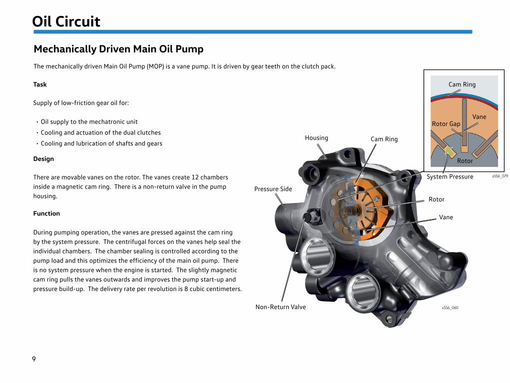
Mechanically Driven Main Oil PumpThe mechanically driven Main Oil Pump (MOP) is a vane pump. It is driven by gear teeth on the clutch pack.
Task
Supply of low-friction gear oil for:
• Oil supply to the mechatronic unit
• Cooling and actuation of the dual clutches
• Cooling and lubrication of shafts and gears
Design
There are movable vanes on the rotor. The vanes create 12 chambers inside a magnetic cam ring. There is a non-return valve in the pump housing.
Function
During pumping operation, the vanes are pressed against the cam ring by the system pressure. The centrifugal forces on the vanes help seal the individual chambers. The chamber sealing is controlled according to the pump load and this optimizes the efficiency of the main oil pump. There is no system pressure when the engine is started. The slightly magnetic cam ring pulls the vanes outwards and improves the pump start-up and pressure build-up. The delivery rate per revolution is 8 cubic centimeters.
Cam Ring
Rotor GapVane
Rotor
System Pressure s556_079
s556_060Non-Return Valve
Pressure Side
Housing Cam Ring
Rotor
Vane
10
Oil Circuit
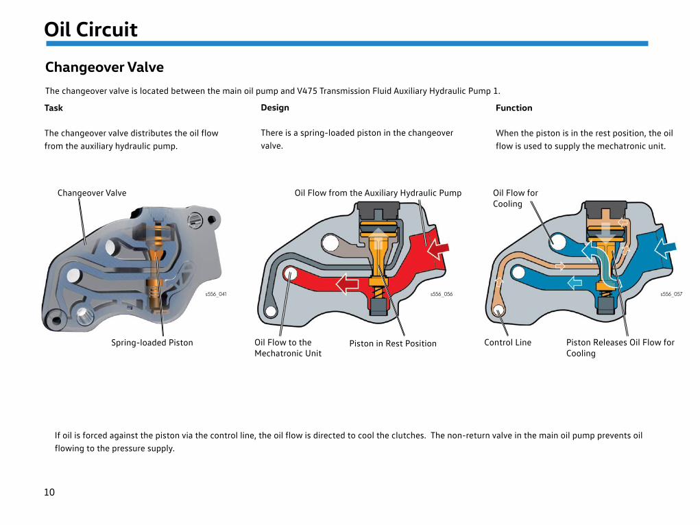
Changeover ValveThe changeover valve is located between the main oil pump and V475 Transmission Fluid Auxiliary Hydraulic Pump 1.
Task
The changeover valve distributes the oil flow from the auxiliary hydraulic pump.
Design
There is a spring-loaded piston in the changeover valve.
Function
When the piston is in the rest position, the oil flow is used to supply the mechatronic unit.
If oil is forced against the piston via the control line, the oil flow is directed to cool the clutches. The non-return valve in the main oil pump prevents oil flowing to the pressure supply.
s556_041 s556_056 s556_057
Changeover Valve
Spring-loaded Piston
Oil Flow from the Auxiliary Hydraulic Pump
Oil Flow to theMechatronic Unit
Piston in Rest Position
Oil Flow forCooling
Control Line Piston Releases Oil Flow forCooling
11
Oil Circuit
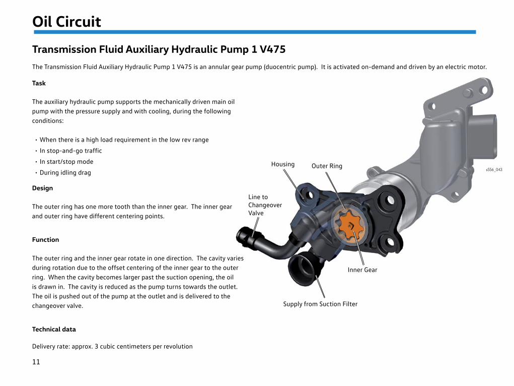
Transmission Fluid Auxiliary Hydraulic Pump 1 V475The Transmission Fluid Auxiliary Hydraulic Pump 1 V475 is an annular gear pump (duocentric pump). It is activated on-demand and driven by an electric motor.
Task
The auxiliary hydraulic pump supports the mechanically driven main oil pump with the pressure supply and with cooling, during the following conditions:
• When there is a high load requirement in the low rev range
• In stop-and-go traffic
• In start/stop mode
• During idling drag
Design
The outer ring has one more tooth than the inner gear. The inner gear and outer ring have different centering points.
Function
The outer ring and the inner gear rotate in one direction. The cavity varies during rotation due to the offset centering of the inner gear to the outer ring. When the cavity becomes larger past the suction opening, the oil is drawn in. The cavity is reduced as the pump turns towards the outlet. The oil is pushed out of the pump at the outlet and is delivered to the changeover valve.
Technical data
Delivery rate: approx. 3 cubic centimeters per revolution
s556_043
Inner Gear
Supply from Suction Filter
Housing
Line to Changeover Valve
Outer Ring
12
Oil Circuit
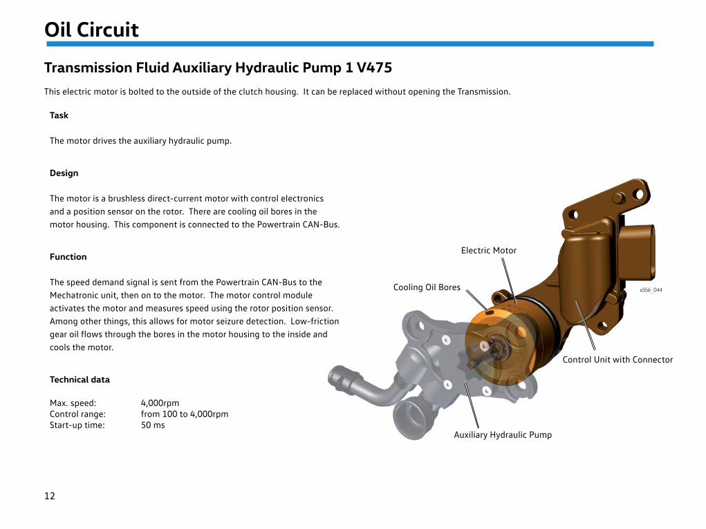
Transmission Fluid Auxiliary Hydraulic Pump 1 V475This electric motor is bolted to the outside of the clutch housing. It can be replaced without opening the Transmission.
s556_044
Task
The motor drives the auxiliary hydraulic pump.
Design
The motor is a brushless direct-current motor with control electronics and a position sensor on the rotor. There are cooling oil bores in the motor housing. This component is connected to the Powertrain CAN-Bus.
Function
The speed demand signal is sent from the Powertrain CAN-Bus to the Mechatronic unit, then on to the motor. The motor control module activates the motor and measures speed using the rotor position sensor. Among other things, this allows for motor seizure detection. Low-friction gear oil flows through the bores in the motor housing to the inside and cools the motor.
Technical data
Max. speed: 4,000rpmControl range: from 100 to 4,000rpmStart-up time: 50 ms
Electric Motor
Cooling Oil Bores
Control Unit with Connector
Auxiliary Hydraulic Pump
13
Oil Circuit
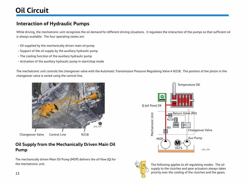
Interaction of Hydraulic PumpsWhile driving, the mechatronic unit recognizes the oil demand for different driving situations. It regulates the interaction of the pumps so that sufficient oil is always available. The four operating states are:
• Oil supplied by the mechanically driven main oil pump
• Support of the oil supply by the auxiliary hydraulic pump
• The cooling function of the auxiliary hydraulic pump
• Activation of the auxiliary hydraulic pump in start/stop mode
The mechatronic unit controls the changeover valve with the Automatic Transmission Pressure Regulating Valve 4 N218. The position of the piston in the changeover valve is varied using the control line.
Oil Supply from the Mechanically Driven Main Oil Pump
The mechanically driven Main Oil Pump (MOP) delivers the oil flow (Q) for the mechatronic unit. The following applies to all regulating modes: The oil
supply to the clutches and gear actuators always takes priority over the cooling of the clutches and the gears.
Temperature OK
Q (oil flow) OK
Return Valve (RV)
RVChangeover Valve
V475
Aux PumpMOP
Mec
hatr
onic
Uni
ts556_058
s556_045
Changeover Valve Control Line N218
N218
14
Oil Circuit
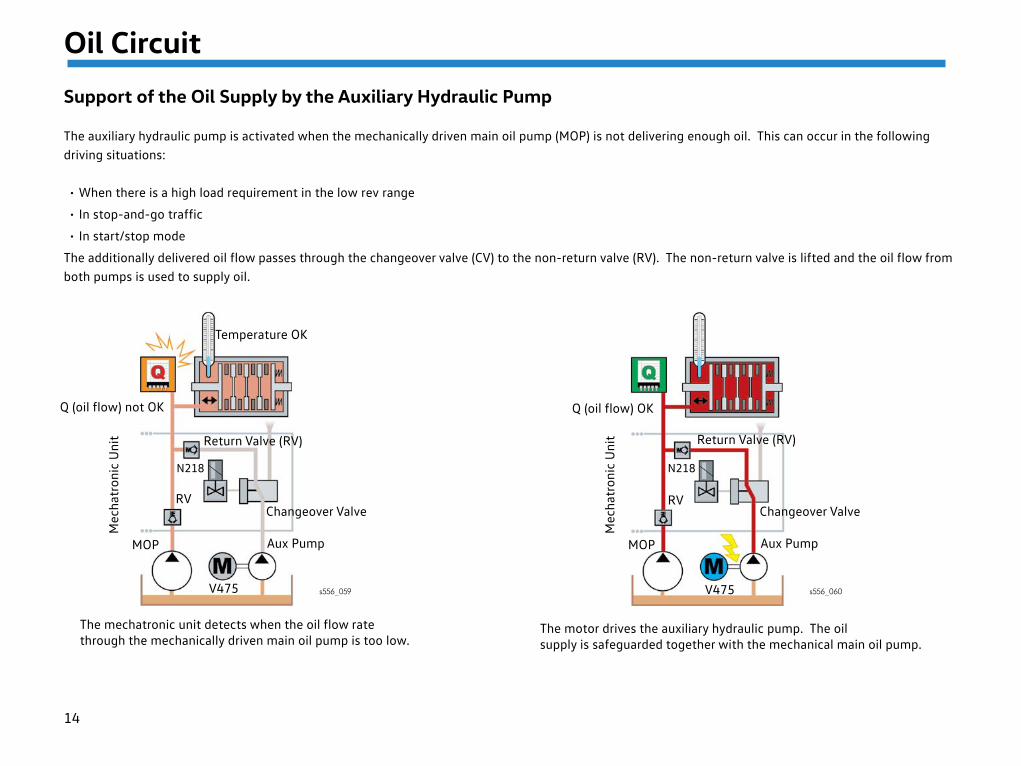
Support of the Oil Supply by the Auxiliary Hydraulic Pump
The auxiliary hydraulic pump is activated when the mechanically driven main oil pump (MOP) is not delivering enough oil. This can occur in the following driving situations:
• When there is a high load requirement in the low rev range
• In stop-and-go traffic
• In start/stop mode
The additionally delivered oil flow passes through the changeover valve (CV) to the non-return valve (RV). The non-return valve is lifted and the oil flow from both pumps is used to supply oil.
RV
V475
MOP
Mec
hatr
onic
Uni
t
RV
V475
MOP
Mec
hatr
onic
Uni
t
s556_059 s556_060
The mechatronic unit detects when the oil flow ratethrough the mechanically driven main oil pump is too low.
The motor drives the auxiliary hydraulic pump. The oilsupply is safeguarded together with the mechanical main oil pump.
Q (oil flow) not OK
Temperature OK
Return Valve (RV)
Changeover Valve
Aux Pump
Changeover Valve
Aux Pump
Return Valve (RV)
Q (oil flow) OK
N218N218
15
Oil Circuit
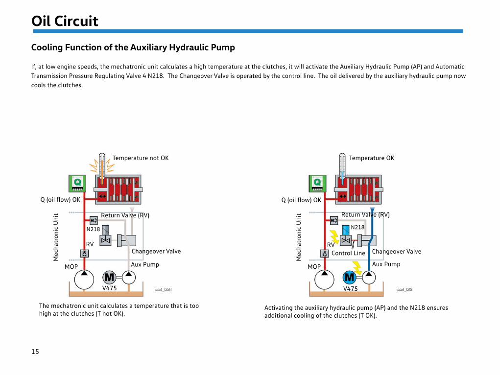
Cooling Function of the Auxiliary Hydraulic Pump
If, at low engine speeds, the mechatronic unit calculates a high temperature at the clutches, it will activate the Auxiliary Hydraulic Pump (AP) and Automatic Transmission Pressure Regulating Valve 4 N218. The Changeover Valve is operated by the control line. The oil delivered by the auxiliary hydraulic pump now cools the clutches.
RV
V475
MOP
Mec
hatr
onic
Uni
t
RV
V475
MOP
Mec
hatr
onic
Uni
t
s556_0561 s556_062
The mechatronic unit calculates a temperature that is toohigh at the clutches (T not OK).
Activating the auxiliary hydraulic pump (AP) and the N218 ensures additional cooling of the clutches (T OK).
Control Line
Temperature OK
Q (oil flow) OK
Return Valve (RV)
Changeover Valve
Aux Pump
Temperature not OK
Return Valve (RV)
Aux Pump
Changeover Valve
Q (oil flow) OK
N218N218
16
Oil Circuit
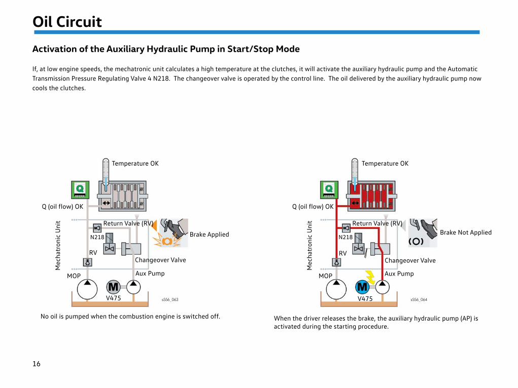
Activation of the Auxiliary Hydraulic Pump in Start/Stop Mode
If, at low engine speeds, the mechatronic unit calculates a high temperature at the clutches, it will activate the auxiliary hydraulic pump and the Automatic Transmission Pressure Regulating Valve 4 N218. The changeover valve is operated by the control line. The oil delivered by the auxiliary hydraulic pump now cools the clutches.
N218
RV
V475
MOP
Mec
hatr
onic
Uni
t
RV
V475
MOP
Mec
hatr
onic
Uni
t
s556_063 s556_064
No oil is pumped when the combustion engine is switched off. When the driver releases the brake, the auxiliary hydraulic pump (AP) is activated during the starting procedure.
Brake Applied Brake Not Applied
Temperature OK
Q (oil flow) OK
Return Valve (RV)
Changeover Valve
Aux Pump
Return Valve (RV)
Changeover Valve
Aux Pump
Q (oil flow) OK
Temperature OK
N218
17
Mechatronic Unit
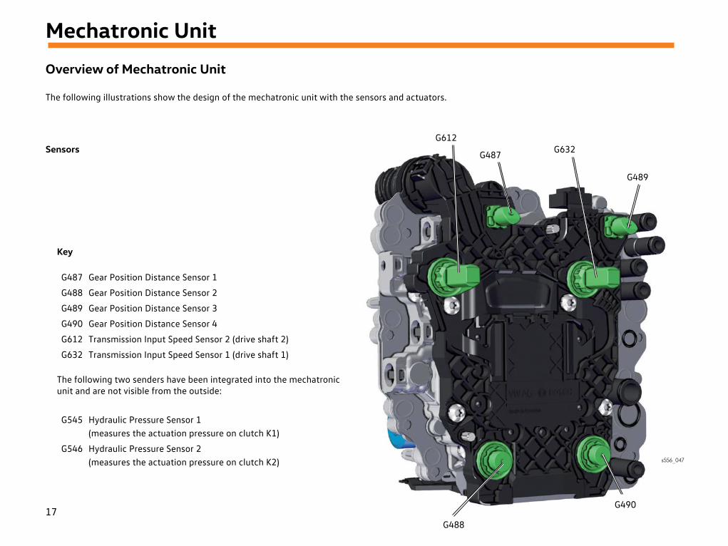
Overview of Mechatronic Unit
The following illustrations show the design of the mechatronic unit with the sensors and actuators.
G487
G612
s556_047
G632
G489
G490
G488
Sensors
G487 Gear Position Distance Sensor 1
G488 Gear Position Distance Sensor 2
G489 Gear Position Distance Sensor 3
G490 Gear Position Distance Sensor 4
G612 Transmission Input Speed Sensor 2 (drive shaft 2)
G632 Transmission Input Speed Sensor 1 (drive shaft 1)
The following two senders have been integrated into the mechatronic unit and are not visible from the outside:
G545 Hydraulic Pressure Sensor 1 (measures the actuation pressure on clutch K1)
G546 Hydraulic Pressure Sensor 2 (measures the actuation pressure on clutch K2)
Key
18
Mechatronic Unit
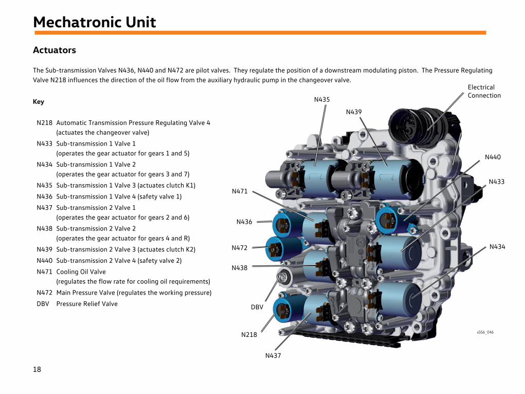
Actuators
The Sub-transmission Valves N436, N440 and N472 are pilot valves. They regulate the position of a downstream modulating piston. The Pressure Regulating Valve N218 influences the direction of the oil flow from the auxiliary hydraulic pump in the changeover valve.
N218 Automatic Transmission Pressure Regulating Valve 4 (actuates the changeover valve)
N433 Sub-transmission 1 Valve 1 (operates the gear actuator for gears 1 and 5)
N434 Sub-transmission 1 Valve 2 (operates the gear actuator for gears 3 and 7)
N435 Sub-transmission 1 Valve 3 (actuates clutch K1)
N436 Sub-transmission 1 Valve 4 (safety valve 1)
N437 Sub-transmission 2 Valve 1 (operates the gear actuator for gears 2 and 6)
N438 Sub-transmission 2 Valve 2 (operates the gear actuator for gears 4 and R)
N439 Sub-transmission 2 Valve 3 (actuates clutch K2)
N440 Sub-transmission 2 Valve 4 (safety valve 2)
N471 Cooling Oil Valve (regulates the flow rate for cooling oil requirements)
N472 Main Pressure Valve (regulates the working pressure)
DBV Pressure Relief Valve
Key N439
N435
s556_046
Electrical Connection
N440
N433
N434
N471
N436
N472
N438
DBV
N437
N218
19
Mechatronic Unit
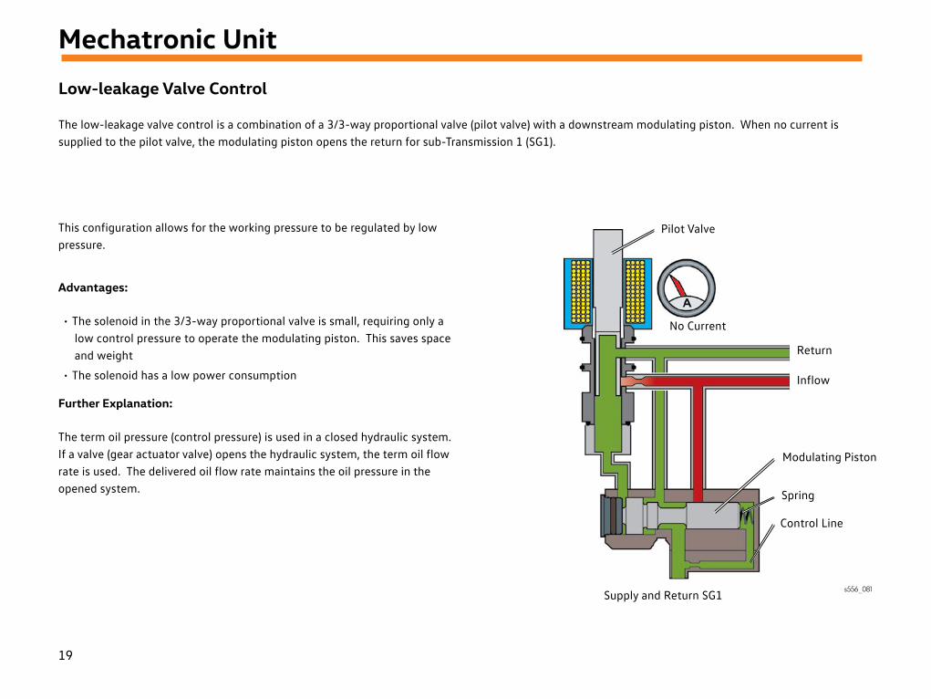
Low-leakage Valve Control
The low-leakage valve control is a combination of a 3/3-way proportional valve (pilot valve) with a downstream modulating piston. When no current is supplied to the pilot valve, the modulating piston opens the return for sub-Transmission 1 (SG1).
This configuration allows for the working pressure to be regulated by low pressure.
Advantages:
• The solenoid in the 3/3-way proportional valve is small, requiring only a low control pressure to operate the modulating piston. This saves space and weight
• The solenoid has a low power consumption
Further Explanation:
The term oil pressure (control pressure) is used in a closed hydraulic system. If a valve (gear actuator valve) opens the hydraulic system, the term oil flow rate is used. The delivered oil flow rate maintains the oil pressure in the opened system.
s556_081Supply and Return SG1
Pilot Valve
No Current
Return
Inflow
Modulating Piston
Spring
Control Line
20
Mechatronic Unit
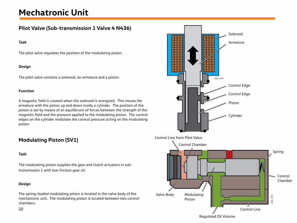
Pilot Valve (Sub-transmission 1 Valve 4 N436)
Task
The pilot valve regulates the position of the modulating piston.
Design
The pilot valve contains a solenoid, an armature and a piston.
Function
A magnetic field is created when the solenoid is energized. This moves the armature with the piston up and down inside a cylinder. The position of the piston is set by means of an equilibrium of forces between the strength of the magnetic field and the pressure applied to the modulating piston. The control edges on the cylinder modulate the control pressure acting on the modulating piston.
Modulating Piston (SV1)
Task
The modulating piston supplies the gear and clutch actuators in sub-transmission 1 with low-friction gear oil.
Design
The spring-loaded modulating piston is located in the valve body of the mechatronic unit. The modulating piston is located between two control chambers.
s556_049
Solenoid
Armature
Control Edge
Piston
Cylinder
Control Edge
Control Line from Pilot Valve
Control Chamber
Valve Body
Spring
Control Line
Regulated Oil Volume
ModulatingPiston
s556
_075
Control Chamber
21
Mechatronic Unit
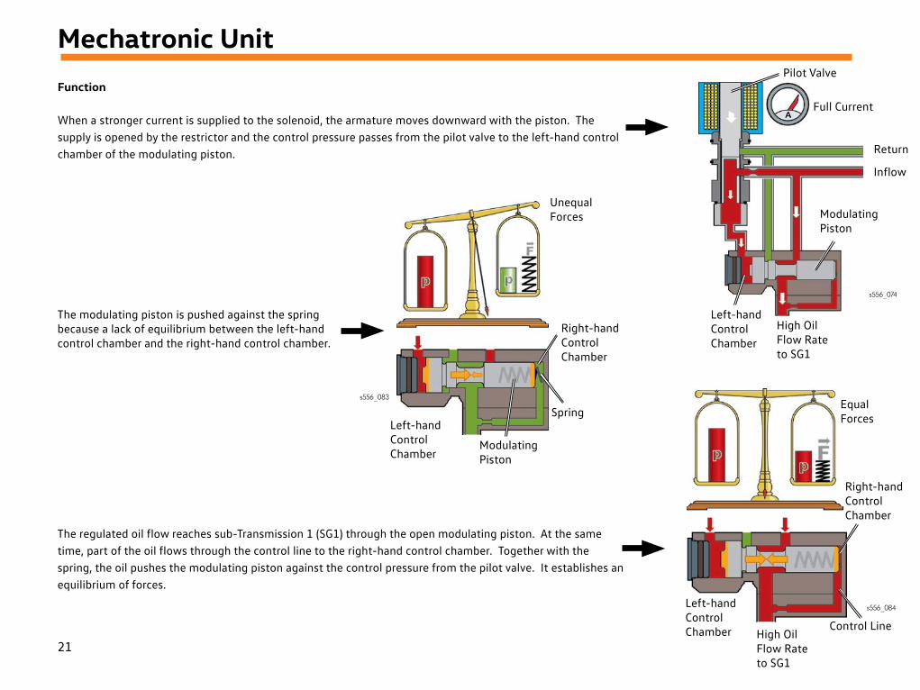
Function
When a stronger current is supplied to the solenoid, the armature moves downward with the piston. The supply is opened by the restrictor and the control pressure passes from the pilot valve to the left-hand control chamber of the modulating piston.
s556_074
Pilot Valve
Full Current
Return
Inflow
Modulating Piston
High Oil Flow Rate to SG1
Left-handControlChamber
s556_083
Left-handControlChamber
Spring
Right-handControlChamber
Unequal Forces
s556_084
Equal Forces
Right-handControlChamber
Left-handControlChamber Control Line
High Oil Flow Rate to SG1
The modulating piston is pushed against the spring because a lack of equilibrium between the left-hand control chamber and the right-hand control chamber.
The regulated oil flow reaches sub-Transmission 1 (SG1) through the open modulating piston. At the same time, part of the oil flows through the control line to the right-hand control chamber. Together with the spring, the oil pushes the modulating piston against the control pressure from the pilot valve. It establishes an equilibrium of forces.
Modulating Piston
22
Mechatronic Unit
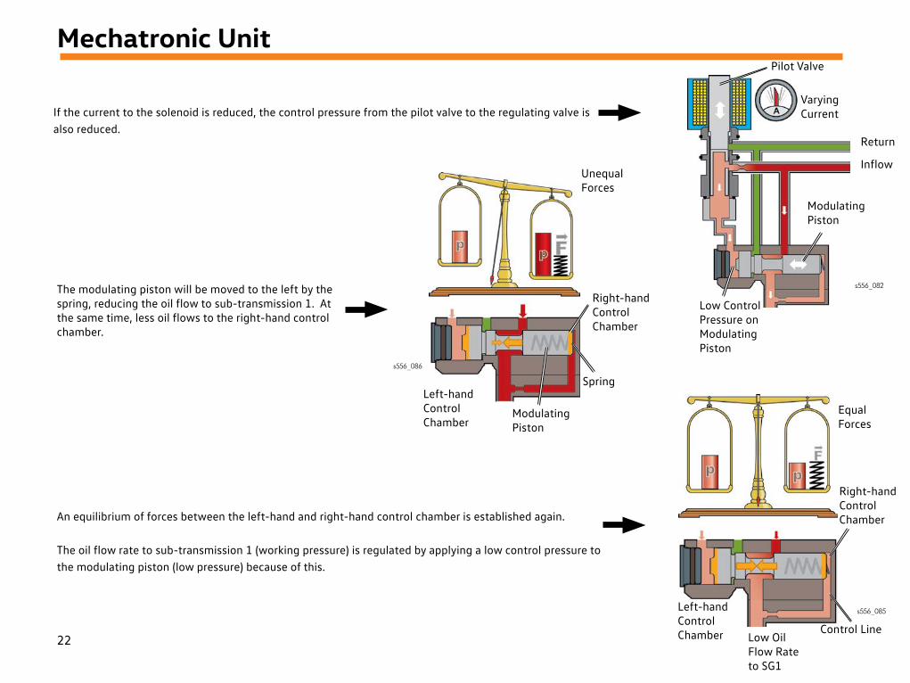
If the current to the solenoid is reduced, the control pressure from the pilot valve to the regulating valve is also reduced.
s556_082
Pilot Valve
Varying Current
Return
Inflow
Modulating Piston
Low Control Pressure on Modulating Piston
s556_086
Left-handControlChamber
Modulating Piston
Spring
Right-handControlChamber
Unequal Forces
s556_085
Equal Forces
Right-handControlChamber
Left-handControlChamber Control Line
Low Oil Flow Rate to SG1
The modulating piston will be moved to the left by the spring, reducing the oil flow to sub-transmission 1. At the same time, less oil flows to the right-hand control chamber.
An equilibrium of forces between the left-hand and right-hand control chamber is established again.
The oil flow rate to sub-transmission 1 (working pressure) is regulated by applying a low control pressure to the modulating piston (low pressure) because of this.
23
Mechatronic Unit
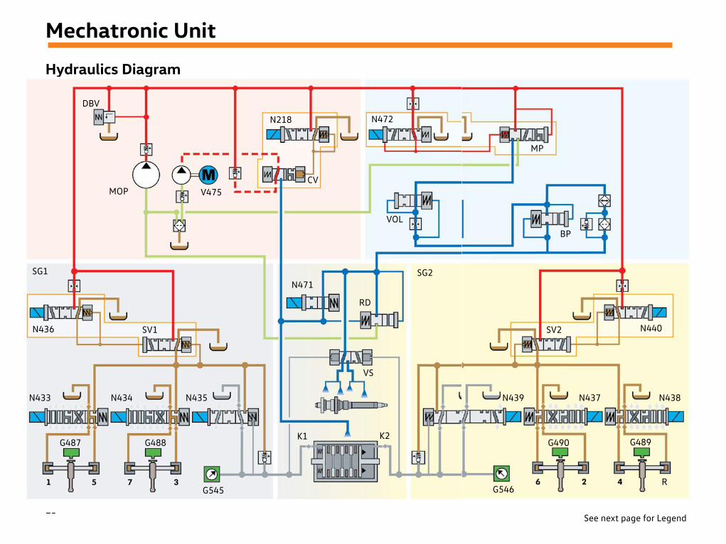
Hydraulics Diagram
See next page for Legend
DBV
MOP
N218 N472
V475CV
VOL
SG1
N436 SV1
N433 N434 N435
G487 G488
G545
N471SG2
RD
VS
K1 K2
MP
BP
N440SV2
N439 N437 N438
G546
G490 G489
R

24
Mechatronic Unit
Hydraulics Diagram LegendG487 Gear Position Distance Sensor 1
G488 Gear Position Distance Sensor 2
G489 Gear Position Distance Sensor 3
G490 Gear Position Distance Sensor 4
G545 Hydraulic Pressure Sensor 1 (measures the actuation pressure on clutch K1)
G546 Hydraulic Pressure Sensor 2 (measures the actuation pressure on clutch K2)
N218 Automatic Transmission Pressure Regulating Valve 4 (actuates the changeover valve)
N433 Sub-transmission 1 Valve 1 (operates the gear actuator for gears 1 and 5)
N434 Sub-transmission 1 Valve 2 (operates the gear actuator for gears 3 and 7)
N435 Sub-transmission 1 Valve 3 (actuates clutch K1)
N436 Sub-transmission 1 Valve 4 (safety valve 1)
N437 Sub-transmission 2 Valve 1 (operates the gear actuator for gears 2 and 6)
N438 Sub-transmission 2 Valve 2 (operates the gear actuator for gears 4 and R)
N439 Sub-transmission 2 Valve 3 (actuates clutch K2)
N440 Sub-transmission 2 Valve 4 (safety valve 2)
N471 Cooling Oil Valve (regulates the flow rate for cooling oil requirements)
N472 Main Pressure Valve (regulates the working pressure)
V475 Transmission Fluid Auxiliary Hydraulic Pump 1
BP Bypass Valve
CV Changeover Valve
DBV Pressure Relief Valve
K1 Clutch 1
K2 Clutch 2
MOP Main Oil Pump
MP Main Pressure Valve
RD Residual Pressure Valve (regulates the cooling oil pressure to 3 bar)
SG1 Sub-transmission 1
SG2 Sub-transmission 2
SV1 Safety Valve 1
SV2 Safety Valve 2
VOL Volume Regulating Valve
VS Valve, Spray Pipe
Working Pressure Circuit
Cooling Circuit
Return
Return
25
Service
MaintenanceThe DSG oil must be changed at the maintenance intervals specified in ELSAPro. The drain plug is located at the rear of the gear case. There is no need to change the oil filter. The filter has been designed for lifetime use.
The following general steps should be performed when changing the oil:
• Oil temperature of 35°C–45°C
• Turn OFF the engine
• Set the selector lever to the “P” position
• Wait 4–5 minutes before draining
Information about TowingIf a vehicle with the 0GC transmission has to be towed, the usual restrictions for automatic transmissiones need to be observed:
• Turn ON ignition
• Activate the manual release mechanism for the parking lock
• Move the selector lever to the “N” position
• The maximum towing speed is 50km/h
• The maximum towing distance is 50km
• If you tow the vehicle with a raised axle, then only raise the front axle.
Reason
If the engine is not running, the oil pump will not be driven and certain parts in the transmission will not be lubricated. If you do not observe the towing requirements, serious transmission damage may result.
The reason for the waiting time is:The oil in the baffle plate needs time to drain into the gear case. You will find exact details on the oil change in the repair manual.
Please observe the further descriptions and information on the topic of towing in the owner's manual.
* Always verify the correct procedure in ElsaPro! ElsaPro has the latest information in case procedures change.
26
Knowledge Assessment
An on-line Knowledge Assessment (exam) is available for this Self-Study Program. The Knowledge Assessment may or may not be required for Certification.
You can find this Knowledge Assessment at: www.vwwebsource.com
For Assistance, please call: Volkswagen Academy, Certification Program Headquarters 1-877-791-4838 (8:00 a.m. to 8:00 p.m. EST)
Or, E-mail: [email protected]
Volkswagen Group of America2200 Ferdinand Porsche DriveHerndon, VA 20171May 2018